Rocket Report
Isabell Vasquez-Echols 7th Astronomy
Introduction
In this project, we will be building a model rocket from scratch. Our goal is to have three successful launches- the test launch, the official launch, and the re-launch for extra credit. Our rocket must have a recovery system in order to accomplish this goal. We are limited to paper materials, water based glues, and a 3D printed nose-cone
We are approaching this project with patience, creativity, and a minimalist mindset. We must be flexible in developing our designs, and when one fails, we must be able to adjust and use our creativity to correct our problems. We want to use as little material as possible in order to save on material cost.
At this moment, we successfully created a sturdy motor mount, designed and printed our nose cone, and we are developing our recovery system. We still need to determine the center of gravity and center of pressure in order to develop our rocket fins.
As of April 11, we have installed our recovery system and designed our fins. We determined the size and shape of our fins through calculations accounting for the Center of Gravity to Center of Pressure ratio. We have our fins cut and attached the first fin. We will wait to attach the others, to assure the wood glue has dried and we have an accurate distance between fins. We have three fins, therefore they each need to be approximately 4.2 cm apart. We
determined this by dividing the circumference of our rocket (12.56cm) by three.
Background
I have no experience in building rockets. However, I have volunteered at Shriners Hospital in the Prosthetics and Orthotics department for two years. This position has given me experience in design-building and tool use.
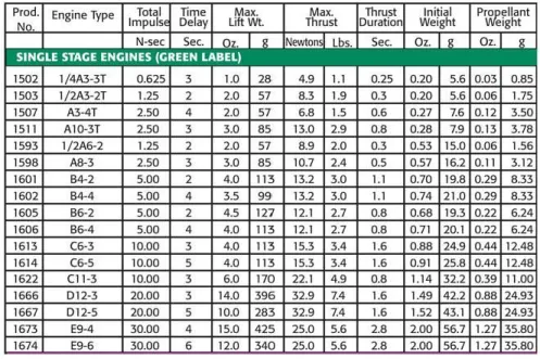
Researchers have spent years studying the Physics of rocketry. For example, Estes has developed mathematical equations to determine engine needed to efficiently fly a stable rocket based on the dimensions of the rocket. This can be seen in Figure 1. This research is important because it ensures safety and stability of the rocket, preventing crashes, fires, and other incidents.
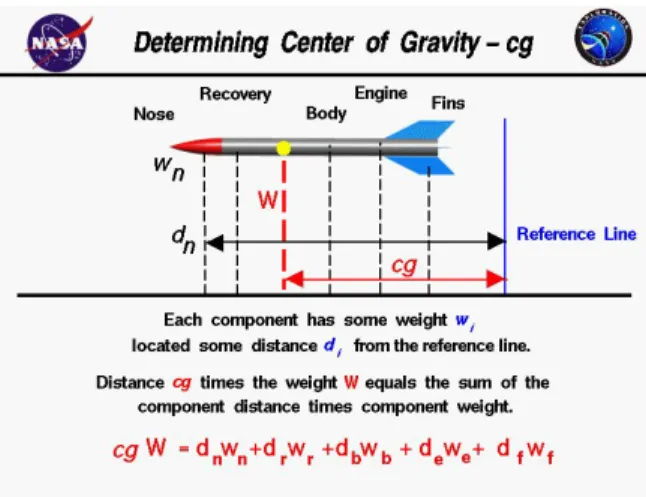
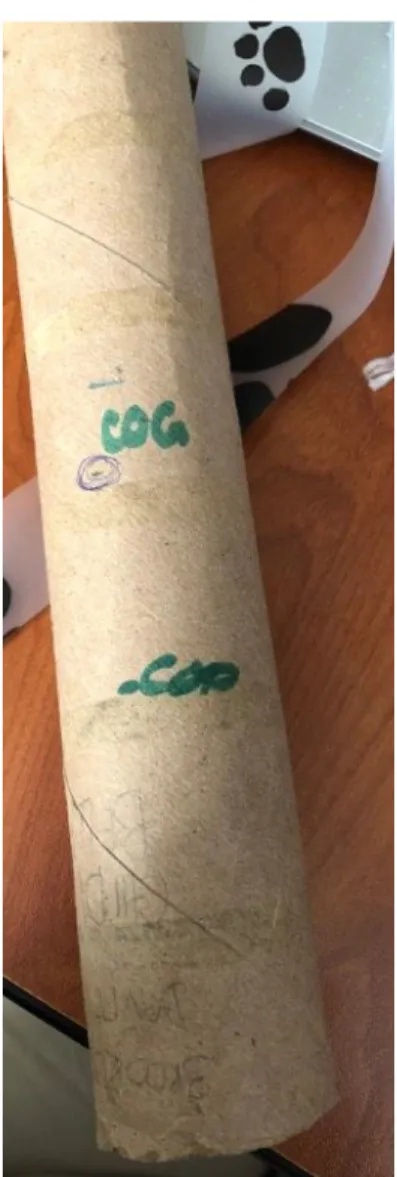
Other important factors in a stable rocket is center of gravity and center of pressure. NASA has done extensive research regarding these factors and have determined center of gravity must be above the center of pressure in order to ensure rocket stability and safety. Center of gravity can be determined by a mathematical equation, as well as mechanically. We determined the center of gravity of our rocket using the mechanical method. This involved placing the rocket on a marker, and the point at which the rocket was completely balanced was our center of
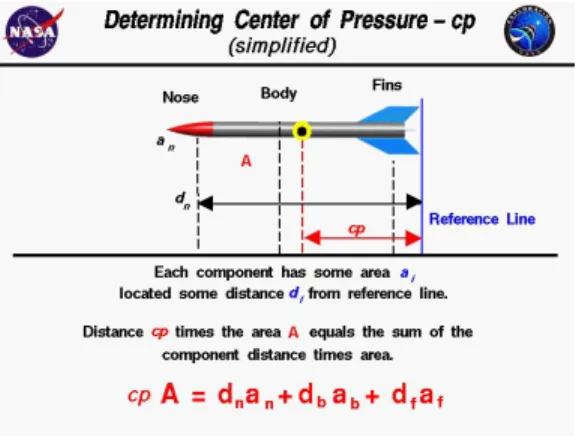
gravity. An example of a center of gravity can be seen in Figure 2. We determined the center of pressure by using calculations developed and simplified by NASA, which can be viewed in Figure 3.
Methods
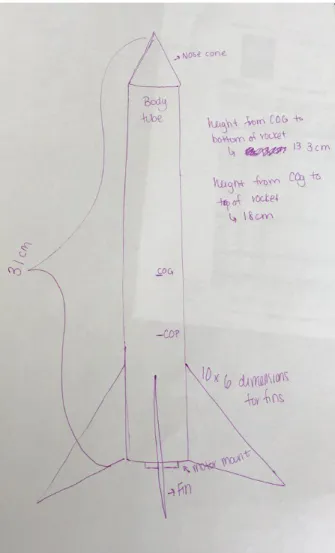
Figure 4: Drawn Diagram of Model Rocket
Motor mount
Figure 5: Motor Mount Design
Figure 6: Motor built into body tube
Body tube
Figure 7: Body Tube
For our body tube, we used a recycled paper towel roll. We decided this would be the most cost and time effective, rather than building our own body tube out of scantrons. This was a standard paper towel roll, with a height of 31 centimeters with the nose cone, with a
Nose cone
Figure 8: 3-D Printed Nose Cone
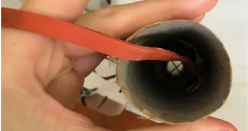
Recovery system
Figure 9: Recovery System
initially had multiple short streamers, but after testing we determined that the longer the streamers, the more effective they were.
COG:COP
Figure 11: Center of Gravity and Center of Pressure
This information was important in our fin design, as we had to bring the center of pressure down below the center of gravity. Our center of pressure ended up being 7 cm from the bottom of the rocket. The larger the fins, the further down the rocket the center of pressure would be pulled. Our recovery system brought our center of gravity higher up on the rocket, resulting in an increase of stability. When performing our stability test, our rocket did extremely well at straightening itself out.
Fins
Figure 12: Fin Design
rocket. Our calculations can be seen in Figure 13. In order to have equally balanced fins, we determined each fin must be 4.2 cm apart. Our final design of our fins can be see in Figure 12. Our final product, with fins attached, can be seen in Figure 14.
Figure 14: Fins Attached to Rocket
Engine selection
Decoration
Works Cited
NASA, NASA, spaceflightsystems.grc.nasa.gov/education/rocket/rktcp.html. NASA, NASA, spaceflightsystems.grc.nasa.gov/education/rocket/rktcg.html. NASA, NASA, spaceflightsystems.grc.nasa.gov/education/rocket/rktstab.html.