RM14K Manual
RM14K
Installation and Programming Manual
This Manual describes the RM14K Industrial Modem, its uses and set up. It also describes the use of the RM14K configuration software.
Effective: 31 July, 2001
Niobrara Research & Development Corporation P.O. Box 3418 Joplin, MO 64803 USA Telephone: (800) 235-6723 or (417) 624-8918 Facsimile: (417) 624-8920
SY/MAX, SY/NET, and Square D are registered trademarks of Square D Company. PowerLogic is a trademark of Square D Company.
Allen-Bradley, A-B, and Data Highway are trademarks of Allen-Bradley Company. MODBUS is a trademark of AEG Modicon Company.
PanelMate is a trademark of EATON IDT. Subject to change without notice.
3
Contents
1
Introduction
... 13Specifications ... 14
Module Specifications ... 14
Modem Specifications ... 15
2
Installation
... 17Module Installation ... 17
RM14KSW Software Installation ... 18
Serial Connection to the RM14K ... 18
LINE Connection to RM14K ... 21
Dial-up Connection ... 21
Four Wire Connection ... 22
Two-Wire Connection ... 22
3
Operation
... 23Memory Configuration ... 23
Command and Status Bits ... 24
Bit 1 (Dial, DCD) ... 24
Bit 2 (RTS, CTS) ... 24
Bit 3 (P-T-P, Multidrop) ... 25
Bit 4 (SY/MAX, Transparent) ... 26
Bit 5 (Auto Answer) ... 26
Bit 6 (Push to Talk) ... 26
Bit 7 (Watch Dog, Dial Input) ... 26
Bits 8 and 9 (Port Parity) ... 27
Bit 10 and 11 (Line Parity) ... 27
Bit 12 (Port Checksum) ... 27
Bit 13 (Line Checksum) ... 28
Bit 14 (Dial-up, Leased Line) ... 28
Bit 15 (Leased Line 2 or 4 Wire, PSTN Off Hook) ... 28
Bit 16 (Ring Indicator) ... 28
Baud Rate ... 29
Phone Number Storage ... 30
Error Register R[6] ... 32
Rack Addressing ... 32
I/O Direction ... 33
4
Drop 201 ... 34
Drop 202 ... 34
Drop 206 ... 34
Configuration in Transparent Mode ... 34
AT Commands (PSTN mode only) ... 34
Dialing String Characters ... 35
S Registers ... 36
Front Panel Control Inputs ... 36
Hayes Switch ... 36
SY/MAX Switch ... 37
Orig Switch ... 37
Ansr Switch ... 37
Cnct Switch ... 37
Hangp Switch ... 37
DIAL Input ... 37
Push-to-Talk Relay Output ... 38
PSTN Operation ... 38
PSTN Connector ... 38
PHONE Connector ... 38
Multidrop Operation ... 39
Leased Line Operation ... 39
LL TX Port ... 39
LL RX Port ... 40
Four Wire Point-to-Point Operation ... 40
Two Wire Point-to-Point Operation ... 40
Multidrop Operation ... 40
Multidrop Tuning Parameters ... 41
Radio Operation ... 41
Password Security Operation ... 41
Caller Station Identification ... 43
4
Configuration Software RM14KSW
... 45Data Entry Keys ... 45
Main Menu ... 46
oNline ... 46
Communication Mode ... 47
Connection Type ... 48
Auto Answer ... 48
Answer on ring ... 48
Wait for Dial Tone ... 48
Wait for Carrier ... 48
Port BPS ... 48
Port Parity ... 48
Port Error Check ... 49
Line BPS ... 49
Line Parity ... 49
Line Error Check ... 49
Watchdog mode ... 49
Number Pointer ... 49
Dial String ... 50
Comma pause time ... 50
DTMF digit length ... 50
Hayes Escape char ... 50
Guard Time ... 50
5
Hayes LF char ... 50
Hayes BS char ... 50
CTS On delay ... 50
CTS Off delay ... 50
Carrier detect ... 51
Answer password ... 51
Last password received ... 51
Status Displays ... 51
Error Displays ... 51
Hot Keys ... 52
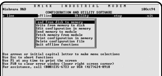
oFfline ... 52
Read from disk to memory ... 53
Write from memory to disk ... 53
Edit configuration in memory ... 53
Send configuration to module ... 53
Fetch configuration from module ... 53
Print configuration in memory ... 53
Delete configuration file ... 54
Quit offline functions ... 54
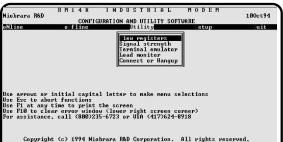
Utility ... 54
View registers ... 54
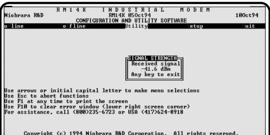
Signal Strength ... 55
Terminal Emulator ... 55
Lead Monitor ... 56
Connect or Hangup ... 57
SETUP ... 57
SY/MAX SETUP ... 57
Personal Computer COM: port ... 58
SY/LINK Connection ... 59
SFI-610 Connection ... 60
Terminal Emulator SETUP ... 60
Command Line Parameters ... 61
Other Included Software ... 61
DIAL.EXE ... 61
HANGUP.EXE ... 62
NRDMODE.EXE ... 62
NRDTERM.EXE ... 62
ZAPREG.EXE ... 63
ZAPREG SY/LINK Connection ... 64
ZAPREG SFI-610 Connection ... 65
5
Dial-up 11 Bit SY/MAX Examples
... 67PC RM14K to Processor RM14K ... 67
Dialing from the Cnct Switch ... 69
Dialing with a Telephone ... 70
Dialing from the PC ... 70
Online Operation ... 70
Manual Hang-up ... 70
Hanging up from the PC ... 71
PC RM14K to NIM RM14K ... 71
Dialing ... 71
Online Operation ... 71
Disconnecting ... 72
PC SY/LINK RM14K to NIM RM14K ... 72
6
Online Operation ... 73
Disconnecting ... 73
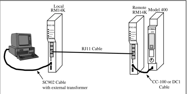
Processor RM14K to Processor RM14K ... 74
Local RM14K Setup ... 75
Remote RM14K Setup ... 75
Model 400 Dialing ... 76
Model 400 Initiated Communication ... 76
Model 400 Disconnecting ... 76
Model 300 Dialing ... 76
Model 300 Initiated Communication ... 77
Model 300 Disconnecting ... 77
NIM RM14K to NIM RM14K ... 77
Originating RM14K Configuration ... 77
Answering RM14K Configuration ... 78
EPE5 RM14K to EPE5 RM14K ... 78
Originating RM14K Configuration ... 79
Answering RM14K Configuration ... 79
RM14K to 2496X ... 80
2496X Configuration ... 80
RM14K Configuration ... 81
RM14K to 1296X ... 82
EPE5 (SPE4) PLOGIC to PowerLogic CM ... 82
Local RM14K Setup ... 82
Remote RM14K Setup ... 82
Personal Computer to PowerLogic CM ... 83
Personal Computer SMS-770 Setup ... 83
Local RM14K Setup ... 83
Remote RM14K Setup ... 84
6
Dial-up 10 Bit SY/MAX Examples
... 85PC Hayes to Processor RM14K ... 85
Hayes Modem Setup ... 86
Remote RM14K Configuration ... 86
Dialing from the PC ... 87
Online Operation ... 87
Hanging up from the PC ... 87
PC RM14K to NIM RM14K ... 87
Dialing ... 88
Online Operation ... 88
Disconnecting ... 88
PC SY/LINK RM14K to NIM RM14K ... 88
Processor RM14K to Processor RM14K ... 88
Local RM14K Setup ... 89
Remote RM14K Setup ... 89
Model 400 Dialing ... 89
Model 400 Initiated Communication ... 91
Model 400 Disconnecting ... 91
Model 300 Dialing ... 91
Model 300 Initiated Communication ... 91
Model 300 Disconnecting ... 91
NIM RM14K to NIM RM14K ... 91
EPE5 RM14K to EPE5 RM14K ... 91
RM14K to 2496X ... 91
2496X Configuration ... 91
7
RM14K to 1296X ... 93
1296X Configuration ... 93
RM14K Configuration ... 93
7
Dial-up Transparent Examples
... 95PNIM to PowerLogic CM ... 95
Local RM14K Setup ... 95
Remote RM14K Setup ... 96
EPE5 (SPE4) PNIM to PowerLogic CM ... 96
Local RM14K Setup ... 96
Remote RM14K Setup ... 97
EPE5 (SPE4) to Micro-1 ... 97
Local RM14K Setup ... 97
Remote RM14K Setup ... 98
EPE5 (SPE4) to Model 50 ... 98
Local RM14K Setup ... 98
Remote RM14K Setup ... 99
PC to Micro-1 ... 99
PC to Model 50 ... 100
PC to BBS ... 101
8
Leased Line SY/MAX Examples
... 103Processor to Processor ... 103
Local RM14K Setup ... 103
Remote RM14K Setup ... 104
Model 400 Initiated Communication ... 104
NIM RM14K to NIM RM14K ... 105
Originating RM14K Configuration ... 105
Answering RM14K Configuration ... 106
EPE5 RM14K to EPE5 RM14K ... 106
Originating RM14K Configuration ... 107
Answering RM14K Configuration ... 107
EPE5 (SPE4) PLOGIC to PowerLogic CM ... 108
Local RM14K Setup ... 108
Remote RM14K Setup ... 109
RM14K to 2496X ... 109
RM14K to 1296X ... 109
9
Leased Line Transparent P-T-P Examples
... 111PNIM to PowerLogic CM ... 111
Local RM14K Setup ... 111
Remote RM14K Setup ... 112
EPE5 (SPE4) PNIM to PowerLogic CM ... 112
Local RM14K Setup ... 112
Remote RM14K Setup ... 113
EPE5 (SPE4) to Micro-1 ... 113
Local RM14K Setup ... 113
Remote RM14K Setup ... 114
EPE5 (SPE4) to Model 50 ... 114
Local RM14K Setup ... 114
8
10 Multidrop Examples
... 117Carrier Control ... 117
RTS/CTS Push to Talk ... 117
Backplane Carrier Control ... 118
RNIM Example ... 118
RM14K Configuration ... 119
RNIM Configuration ... 120
11 Connector Pinouts
... 121RS-422 ports on RM14K (DE9S with slide lock posts) ... 121
PSTN RJ11 Connector ... 122
PHONE RJ11 Connector ... 122
LL TX RJ11 Connector ... 122
LL RX RJ11 Connector ... 122
12 Recommended Cabling
... 123Cabling required to configure an RM14K ... 123
RM14K to personal computer cabling ... 123
Cabling required to connect the RM14K port to an external device ... 124
RM14K RS-422 to SY/MAX RS-422 port (Without Handshaking) ... 124
RM14K RS-422 to SY/MAX RS-422 port (With Handshaking) ... 124
RM14K RS-422 port to PowerLogic RS-485 (4-wire Multidrop Master) ... 125
13 Troubleshooting
... 127Step 1 - RM14K Lights and Sounds ... 127
Step 2 - Communicating to the Modem ... 128
Last Step - Reset the Modem ... 129
Statistics Registers ... 129
General Module Information ... 129
Port and Line Information ... 132
Appendix A Federal Communications Commission Radio Frequency
Interference Statement
... 135FCC Requirements: ... 135
Service Requirements ... 136
DOC Notification and Repair Information ... 136
Appendix B Serial Communication Overview
... 137Hardware Overview ... 137
RS-232 ... 137
RS-422 ... 142
RS-485 (four wire) ... 143
RS-485 (two wire) ... 143
20mA Current Loop ... 144
Hardware Handshaking ... 145
9
Binary Representation of Data ... 146
Start Bit ... 146
Data Bits ... 146
Parity Bit ... 146
Stop Bit ... 146
Message Determination ... 147
Hexadecimal numbers ... 147
ASCII characters ... 148
Software Handshaking ... 148
X-ON ... 148
X-OFF ... 149
Appendix C NR&D on the Internet
... 151Appendix D Command and Register Summary
... 153RM14K Register List ... 153
Command and Status Bit List ... 154
RS-422 Port Baud Rate List ... 155
PSTN and LL Port Baud Rate List ... 155
Multidrop LL Port Baud Rate List ... 155
Error Register Bit List ... 156
Dialing String Character List ... 156
Hayes Command List ... 157
"S" Register List ... 158
Special Function Register List ... 159
Figures
Figure 1-1 RM14K Front Panel ... 16Figure 2-1 RM14K initialization ... 19
Figure 2-2 RM14KSW Main Menu ... 19
Figure 2-3 Sy/Max Setup Window ... 20
Figure 2-4 RM14KSW oNline ... 21
Figure 2-5 PSTN Connection Example ... 21
Figure 2-6 Four Wire Point-to-Point Example ... 22
Figure 2-7 Two-Wire Point-to-Point Example ... 22
Figure 3-1 PSTN Connector ... 38
Figure 3-2 PHONE Connector ... 39
Figure 3-3 LL TX Connector ... 39
Figure 3-4 LL RX Connector ... 40
Figure 4-1 Main Menu Screen ... 46
Figure 4-2 oNline Screen ... 47
Figure 4-3 oFfline Menu ... 52
Figure 4-4 Utility Menu ... 54
Figure 4-5 View Registers ... 55
Figure 4-6 Signal Strength ... 55
Figure 4-7 Terminal Emulator ... 56
Figure 4-8 Lead Monitor ... 56
10
Figure 4-10 Setup Menu ... 57
Figure 4-11 SY/MAX Setup Screen ... 58
Figure 4-12 SY/LINK Setup Screen ... 59
Figure 4-13 Terminal Emulator Setup Screen ... 60
Figure 4-14 View Registers ... 64
Figure 5-1 RM14K to RM14K Dial-up Example ... 68
Figure 5-2 Personal Computer to NIM example ... 72
Figure 5-3 SY/LINK to NIM Example ... 74
Figure 5-4 Processor to Processor Example ... 75
Figure 5-5 SY/NET Blue Hose Dial-up Bridge ... 77
Figure 5-6 SY/NET Ethernet Dial-up Bridge ... 79
Figure 5-7 RM14K to 2496X Example ... 81
Figure 5-8 EPE5 PLOGIC to PowerLogic CM ... 82
Figure 5-9 Personal Computer to PowerLogic CM ... 84
Figure 6-1 Hayes 10 bit to RM14K Dial-up Example ... 86
Figure 6-2 Personal Computer to NIM 10 Bit example ... 88
Figure 6-3 Processor to Processor Example ... 89
Figure 6-4 RM14K to 2496X Example ... 92
Figure 6-5 RM14K to 1296X Example ... 93
Figure 7-1 PNIM CRM-565 Setup ... 96
Figure 7-2 EPE5 PNIM to PowerLogic CM ... 97
Figure 7-3 EPE5 to Micro-1 ... 98
Figure 7-4 EPE5 to Model 50 ... 99
Figure 7-5 Personal Computer to Micro-1 ... 100
Figure 7-6 Personal Computer to Model 50 PLC ... 101
Figure 7-7 BBS Operation ... 102
Figure 8-1 Processor to Processor Leased Line Example ... 104
Figure 8-2 SY/NET Blue Hose Leased Line Bridge ... 105
Figure 8-3 SY/NET Ethernet Leased Line Bridge ... 107
Figure 8-4 EPE5 PLOGIC to PowerLogic CM ... 109
Figure 9-1 PNIM CRM-565 Setup ... 112
Figure 9-2 EPE5 PNIM to PowerLogic CM ... 113
Figure 9-3 EPE5 to Micro-1 ... 114
Figure 9-4 EPE5 to Model 50 ... 115
Figure 10-1 Multidrop Push-to-Talk Timing ... 118
Figure 10-2 RNIM Multidrop Example ... 119
Figure 11-1 DE9S Configuration ... 121
Figure 11-2 PSTN Connector ... 122
Figure 11-3 PHONE Connector ... 122
Figure 11-4 LL TX Connector ... 122
Figure 11-5 LL RX Connector ... 122
Figure 13-1 CLEAR Reset Switch ... 129
Figure B-1 DTE to Modem connection ... 137
Figure B-2 Null Modem connection ... 141
Figure B-3 RS-422 Setup ... 142
Figure B-4 RS-485 Four Wire Setup ... 143
Figure B-5 RS-485 Two wire Multidrop Setup ... 144
11
Tables
Table 2-1 RM14K Factory Default Settings ... 18
Table 2-2 RM14K Software List ... 18
Table 3-1 RM14K Register List ... 23
Table 3-2 Command and Status Bit List ... 25
Table 3-3 RS-422 Port Baud Rate Table ... 29
Table 3-4 PSTN and LL Port Baud Rates ... 29
Table 3-5 Multidrop LL Port Baud Rates ... 30
Table 3-6 Dialing String Characters ... 31
Table 3-7 Phone Number Storage Example ... 31
Table 3-8 Phone Number Storage Example 2 ... 31
Table 3-9 Error Register Bit List ... 32
Table 3-10 Rack Addressing Example ... 33
Table 3-11 Hayes Command List ... 35
Table 3-12 Dialing String Characters ... 35
Table 3-13 "S" Register List ... 36
Table 3-14 PSTN Port Pinout ... 38
Table 3-15 PHONE Port Pinout ... 39
Table 3-16 LL TX Port Pinout ... 39
Table 3-17 LL RX Port Pinout ... 40
Table 3-18 Multidrop Tuning Registers ... 41
Table 3-19 Password Dialing Example ... 42
Table 3-20 Password Dialing with Continuation ... 43
Table 4-1 RM14K Software ... 61
Table 5-1 Local RM14K Configuration Register List ... 69
Table 5-2 Remote RM14K Configuration Register List ... 69
Table 5-3 Example Routing Summary ... 71
Table 5-4 Example Routing Summary ... 72
Table 5-5 Example Routing Summary ... 73
Table 5-6 Local RM14K Configuration ... 75
Table 5-7 Remote RM14K Configuration ... 76
Table 5-8 Originating RM14K Configuration ... 78
Table 5-9 Answering RM14K Configuration ... 78
Table 5-10 Originating RM14K Configuration ... 80
Table 5-11 Answering RM14K Configuration ... 80
Table 5-12 RM14K Configuration for 2496X 11 bit use ... 81
Table 6-1 Remote RM14K Configuration Register List ... 87
Table 6-2 Local RM14K Configuration ... 90
Table 6-3 Remote RM14K Configuration ... 90
Table 6-4 RM14K Configuration for 2496X 10 bit use ... 92
Table 6-5 RM14K Configuration for 1296X 10 bit use ... 94
Table 8-1 Local RM14K Configuration ... 104
Table 8-2 Remote RM14K Configuration ... 105
Table 8-3 Originating RM14K Configuration ... 106
Table 8-4 Answering RM14K Configuration ... 106
Table 8-5 Originating RM14K Configuration ... 107
Table 8-6 Answering RM14K Configuration ... 108
12
Table 11-1 PSTN Port Pinout ... 122
Table 11-2 PHONE Port Pinout ... 122
Table 11-3 LL TX Port Pinout ... 122
Table 11-4 LL RX Port Pinout ... 122
Table B-1 25 pin RS-232 port ... 139
Table B-2 Type A 9 pin RS-232 port ... 140
Table B-3 Type B 9 pin RS-232 port ... 140
Table B-4 DB25 Null Modem ... 141
Table B-5 DE9 Null Modem ... 141
Table B-6 SY/MAX DE9S RS-422 Pinout ... 142
Table B-7 Decimal, Hex, Binary ... 148
Table B-8 ASCII Table ... 150
Table D-1 Options Register Bits ... 159
Table D-2 Connection/Disconnection Source List ... 160
RM14K Manual 1 Introduction 13
1
Introduction
The Niobrara RM14K Industrial Modem is a SY/MAX® compatible modem which mounts in the RRK series register rack. The RM14K is able to operate on ordinary Dial-up Public Switched Telephone Networks (PSTN), 2 and 4-wire "Dry" leased-lines, and Radios to provide a long distance serial com-munication link. The RM14K is able to communicate over the audio connection at up to 14.4K baud. The RM14K is compatible with the Niobrara 2496X and 1296X modems. With proper configuration and software, the RM14K is compatible with standard 10 bit Hayes compatible modems.
The RM14K is available in the following configurations: • One (1) RS-422 port, the RM14K-D
See Figure 1-1 for the front panel configuration of the RM14K.
The RM14K is able to function in two modes: SY/MAX and Transparent (Hayes).
The SY/MAX capabilities of RM14K make the module ideal for remote programming of processors, interconnecting of remote SY/NET networks, and remote monitoring of SY/MAX devices such as PowerLogic Circuit Monitors. While in SY/MAX mode, the RM14K will respond to certain special SY/MAX routes for configuration and control of the modem; either from the RS-422 port or the Line port.
The Transparent mode allows non-SY/MAX communication over telephone lines, leased lines, and ra-dios at baud rates of up to 14.4K baud, in 10 or 11 bit modes. This is useful for communicating with PNIM, IDEC, MODBUS, A-B, and ASCII devices. While in Transparent PSTN mode, the RM14K will respond to a set of Hayes AT commands for configuration and control of the modem from the RS-422 port.
The RM14K may be controlled from the backplane regardless of the operating mode. The PLC may rack address up to 64 registers for the RM14K. The first register controls the modem while the second register provides status information. Other registers are provided for baud rate control, error reporting, storage of telephone numbers, and general I/O usage.
Additionally, registers 65 through 2048 are provided for non-volatile storage of telephone numbers, or general mailbox usage. Other registers in the 8000 through 8192 range provide other modem control settings and module information. All registers greater than 64 must be accessed from either the Data port or Line port in SY/MAX mode.
14 Introduction 1 RM14K Manual The RM14K also provides a password security feature for limiting access to systems from other PSTN users. If the password feature is enabled, a four digit DTMF code must be entered before the modem will initiate the answer sequence. The current password and a display of the last password entered are available to the PLC from the backplane in real time. This feature may also be used as a "Caller ID" system by assigning a unique password to be automatically dialed from each remote station.
Specifications
Module Specifications
Mounting Requirements
One register slot of a Square D Class 8030 Type CRK, DRK, GRK, HRK, or
RRK I/O or the NR&D NRK1 or NRK2 rack assembly.
Current Draw on SY/MAX power supply
800 mA
Operating Temperature
0 to 60 degrees C operating. -40 to 80 degrees C storage.
Humidity Rating
up to 90% noncondensing
Pressure Altitude
-200 to +10,000 feet MSL
Communication Port
9 pin D-connector, RS-422/485 compatible. Selectable baud rate, parity, error
check, protocol mode. Active RTS/CTS handshake lines.
Indicator lights
8 LEDs: Power, Off Hook, Carrier, Transmit, Ring, Ans Enbl, RX, and TX.
Switches
3 center off momentary contact double throw:
Hayes/SY/MAX
Originate/Answer
Connect/Hangup
Physical Dimensions
Single width module.
Wt: 2.5 lb.
W: 1.5 in.
H: 12.8 in.
D: 6.6 in.
Dial Input
Optically isolated voltage input. Active range: 12 - 120 DC to 400 Hz. Current
at 12 VDC 5 mA resistive. Load at 120 VAC 30 mA resistive.
PTT Output
Form 1A normally open single pole reed relay. 1 Amp non-inductive 150 V
DC to 400 Hz.
RM14K Manual 1 Introduction 15
Modem Specifications
Modulation and Data rate
Full Duplex
Bell 103 300 bps, V.22 1200 bps, V.22 bis 2400 bps,
V.32 QAM 4800 bps, V.32 bis TCM 7200 bps, V.32 TCM 9600 bps,
V.32 bis TCM 14400 bps
Half Duplex (for controlled carrier applications)
V.26 bis 1200 bps, V.27 ter 2400 bps, V.29 QAM 4800, 7200, and 9600 bps,
V.17 TCM 14,400 bps.
DTMF Dial and Receive
0 through 9, #, *, A, B, C, D, Hookflash.
Tone burst duration software adjustable.
DTMF sensitivity over voice, 6 dB.
Transmit level
-9dBm permissive in PSTN mode, 0 to -15 dBm software selected in private
line mode. (Consult factory before adjusting transmit level). Transmitter
equalized by digital compromise equalizer.
Receiver sensitivity
0 to -37 dBm with automatic gain control and adaptive equalizer. Carrier
re-covery tolerance +/- 7 Hz.
Ring detect
45 to 120 VRMS, 15 to 68 Hz. Cadence 10 seconds max. Software selectable
auto answer 1 to 255 rings.
Echo canceller
16 Introduction 1 RM14K Manual
Figure 1-1 RM14K Front Panel
TX RX
DIAL
PTT Cnct Hngp
Orig Ansr Hayes SY/MAX
PHONE
PSTN
LL TX
LL RX Ans Enbl Ring Transmit Carrier Off Hook POWER
RM14K
Mode Indicators (LEDs)
Power (Green) - lights when module is powered and has passed
self-test.
Off Hook (Red) - lights when modem is attached to PSTN
connec-tion. The Phone connection is disconnected from the PSTN when on. Also lit in two wire Leased Line mode.
Carrier (Red) - lights when modem has detected carrier. Transmit (Yellow) - lights when modem has carrier energy. Ring (Red) - lights when the PSTN connection is ringing. Ans Enbl (Red) - lit when the Auto Answer feature is enabled.
Audio Connections
Phone - RJ11 for connecting a telephone to the RM14K for voice
communication. This port is connected to the PSTN port as long as the RM14K is not Off Hook.
PSTN - RJ11 connector for attaching the RM14K to a PSTN (analog
phone line) for dial-up usage.
LL TX - RJ11 for the transmit pair of a four wire leased line. Also
functions as the audio output for radio applications.
LL RX - RJ11 for the Receive pair of a four wire leased line. Also
functions as the audio input for radio applications.
Momentary Contact Switches
Hayes/SY/MAX - Hayes selects Transparent mode. SY/MAX
se-lects SY/MAX compatible mode.
Orig/Ansr - Orig selects originate mode for outbound dialing. Ansr
selects Auto Answer mode for unattended answering.
Cnct/Hngp - When Cnct is toggled, modem goes off hook and
op-tionally dials a preprogrammed number. Hngp causes the modem to hang up.
Communication Port
Female RS-422 serial communication port. Features full RTS/CTS handshaking and SY/MAX compatible pinout.
TX (Yellow) - Lights when data is transmitted from serial port. RX (Yellow) - Lights when data is received at serial port.
Input/Output Contacts
DIAL (Input) - 12 to 120 Volt input AC or DC. Causes unit to dial a
preprogrammed telephone number. Also used as the input in Watch-dog mode.
RM14K Manual 2 Installation 17
2
Installation
Module Installation
1 Remove power from the rack.
2 Mount the RM14K in an available slot in the register rack. Secure the screw at the bottom of the module.
3 Apply power to the rack. The lights on the RM14K will strobe during startup. The green power light should remain lit; depending upon the configuration, the yellow Transmit light and the red Ans Enbl light may also remain lit. The lights beneath the 9 pin RS-422 port on the illuminate only when data is passing through the port.
4 The RM14K will default to the settings held in non-volatile RAM. Factory default settings are shown in Table 2-1.
Many installations of the RM14K will require only the installation of the unit in a rack and configura-tion using the front panel switches. More advanced applicaconfigura-tions may require the default settings to be modified by one of the following methods:
• Front panel center off momentary contact switches.
• Modification of setup registers from the RS-422 port using SY/MAX messages • Modification of rack addressed setup registers from the PLC backplane.
The most convenient method for modifying the configuration of the RM14K is through the use of the RM14KSW software.
Warning
Do NOT install or remove the RM14K with power applied to the Rack. Turn OFF power at the power supply. Damage to the equipment may occur if the power is on during installation.
18 Installation 2 RM14K Manual
Table 2-1 RM14K Factory Default Settings
RM14KSW Software Installation
This MS-DOS compatible program runs on an IBM compatible personal computer. The software is distributed on a 3.5" 720K floppy and is compressed using an industry standard .ZIP format. For auto-matic installation perform the following steps.
1 Insert the floppy into a drive and run the INSTALL program from that drive. 2 Enter the floppy drive name that contains the distribution disk.
3 Select RM14KSW from the list of softwares to install.
4 Enter a directory name to install the RM14KSW software. It is recommended that a directory RM14K be used for the installation on your hard drive.
5 Once INSTALL is finished copying and expanding the files, exit by pressing the ESC key until the DOS prompt is reached.
6 Change to the RM14K directory and perform a directory with the following commands:
C:
CD \RM14K DIR
Table 2-2 lists the files that should appear in the directory. These files are described in Chapter 4 on page 45.
Table 2-2 RM14K Software List
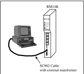
Serial Connection to the RM14K
A physical connection must be made from the personal computer to the RM14K in order for
RM14KSW to be able to fully function. This link may be a serial connection from a COM port on the personal computer to the RS-422 port on the RM14K. Usually an RS-232 to RS-422 converter is re-quired for this connection and the Niobrara SC902 (or SC406) smart cable is recommended. The RM14K has active RTS/CTS handshake lines and requires the external power supply to be used with the smart cable. If the personal computer has a SY/LINK card, the RS-422 port on the SY/LINK card may be used to directly connect to the RM14K. Refer to page 59 for additional information on the SY/LINK setup.
Parameter RS-422 Port Modem Port
Mode SY/MAX SY/MAX Dial-up
Baud Rate 9600 14400
Parity EVEN EVEN
Data Bits 8 8
Stop Bits 1 1
Checksum BCC BCC
File Name Description
DIAL.EXE Hayes AT dialing utility. HANGUP.EXE Hayes AT hang-up utility.
NRDMODE.EXE Advanced COM port configuration utility. NRDTERM.EXE Terminal emulator.
RM14KSW.EXE SY/MAX protocol configuration program. ZAPREG.EXE SY/MAX register viewer.
RM14K Manual 2 Installation 19 Connect your personal computer to the RM14K. It is assumed here that this connection will be made from COM1: of the personal computer using an SC902 Smart Cable. The external power supply must be used to power the SC902.
Start RM14KSW.EXE to communicate with the RM14K in SY/MAX mode. C:\RM14K> RM14KSW
The screen should appear as in Figure 2-2.
Figure 2-2 RM14KSW Main Menu
In order to communicate with the RM14K, the personal computer must be configured to match the communication parameters of the RM14K. This is accomplished using the SY/MAX Setup screen within RM14KSW.
1 From the Main menu, press "S" for Setup.
2 From the Setup menu, press "S" for Sy/Max setup. A window should open as in Figure .
3 At this point, set the parameters according to the local requirements. For a direct connection with an SC902 cable and COM1: the following parameters are suggested:
with external transformer RM14K
POWER Off Hook Carrier Ring Ans Enbl
RM14K
SC902 Cable
20 Installation 2 RM14K Manual a. Connection type Sy/Max COM:
b. Port COM1:
c. Baud Rate 9600
d. Data Bits 8
e. Stop Bits 1
f. Parity EVEN
g. Error Check BCC
h. Route 1,201
4 After Entering the Route, a confirmation window will appear to prompt the user to save the setup to disk. Select "Y" for Yes.
Figure 2-3 Sy/Max Setup Window
The personal computer is now ready to communicate with the RM14K. Press "N" for oNline and the TX and RX lights on the RM14K should start flashing. The screen on the personal computer should look something like Figure 2-4. The arrow keys are used to move the cursor around. Parameters may be changed by toggling values with the space bar, - and + keys, or by direct entry of numeric fields. Use caution while changing fields that relate to the RS-422 Port; communication may be interrupted if values such as baud rate, parity, or checksum are changed while online.
RM14K Manual 2 Installation 21
Figure 2-4 RM14KSW oNline
LINE Connection to RM14K
It is suggested that the Operation chapter of this manual be read before actual connection to the tele-phone line is made.
Dial-up Connection
For a simple dial-up connection, use the included RJ11 cable to connect the PSTN socket on the RM14K to a standard telephone outlet. (Figure 2-5) If desired, a standard telephone may be connected to the PHONE RJ11 connector on the RM14K. The telephone may be used for voice applications or for manually dialing modem connections. The telephone will be connected to the LINE whenever the RM14K is on hook. While oNline, choose PSTN as the connection type, SY/MAX as the operating mode and have the Line settings of both modems match. The RM14K should now be ready to dial a remote sight for connection. Use a route of 1,201 to access the Local RM14K, a route of 1,202 to ac-cess the Remote RM14K and NONE route to acac-cess the Model 400.
Figure 2-5 PSTN Connection Example
with external transformer
RM14K
POWER Off Hook Carrier Ring Ans Enbl
RM14K Remote Public Switched
Telephone Network RM14K
POWER Off Hook Carrier Ring Ans Enbl
RM14K Local
SC902 Cable
Optional Phone
400
SY/MAX
Model 400
CC-100 or DC1 Cable
22 Installation 2 RM14K Manual
Four Wire Connection
For Four Wire Leased Line Point-to-Point applications, connect the LL TX pair from one modem to the LL RX pair on the other RM14K (Figure 2-6). For an office simulation, simply use the included RJ11 cables to make these connections. Make sure to set one RM14K for Originate, and the other RM14K for Auto-Answer. While oNline, choose Four Wire Leased Line as the connection type, SY/MAX as the operating mode and have the Line settings of both modems match. The modes should quickly ob-tain carrier. Use a route of 1,201 to access the Local RM14K, a route of 1,202 to access the Remote RM14K and NONE route to access the Model 400.
Figure 2-6 Four Wire Point-to-Point Example
Two-Wire Connection
Two Wire Leased Line connections are made by simply connecting the LL TX pairs together. (Figure 2-7) For Point-to-Point connections, select one RM14K as Originate, and the Other RM14K as Auto-Answer. While oNline, choose Two-Wire Leased Line as the connection type, SY/MAX as the operat-ing mode and have the Line settoperat-ings of both modems match. The Off Hook light should come on and the modems should quickly obtain carrier. Use a route of 1,201 to access the Local RM14K, a route of 1,202 to access the Remote RM14K and NONE route to access the Model 400.
Figure 2-7 Two-Wire Point-to-Point Example
with external transformer
RM14K POWER Off Hook Carrier Ring Ans Enbl RM14K Remote RM14K POWER Off Hook Carrier Ring Ans Enbl RM14K Local SC902 Cable RJ11 Cables 400 SY/MAX Model 400
CC-100 or DC1 Cable
with external transformer
RM14K POWER Off Hook Carrier Ring Ans Enbl RM14K Remote RM14K POWER Off Hook Carrier Ring Ans Enbl RM14K Local SC902 Cable RJ11 Cable 400 SY/MAX Model 400
CC-100 or DC1 Cable
RM14K Manual 3 Operation 23
3
Operation
Memory Configuration
The operation of the RM14K is determined by the configuration in memory and by the change of state of various inputs to that memory. These inputs include the toggle switches on the front panel, the dial input contact on the front panel, register rack data from the PLC, incoming SY/MAX messages from the RS-422 port, incoming SY/MAX messages on the modem port, or incoming Hayes messages on the RS-422 port. The RM14K’s internal user-accessible memory is represented as SY/MAX processor equivalent registers. All configuration parameters are stored and displayed in these registers. A list of available registers is shown in Table 3-1.
Table 3-1 RM14K Register List
Register Function Non-volatile Rack Addressable
Valid Data Values (decimal)
1 Command Bits Yes Yes (PLC Output) See Table 3-2
2 Status Bits Determined on power-up. Yes (PLC Input) See Table 3-2
3 Port Baud Rate Yes Yes (Either) See Table 3-3
4 Line Baud Rate Yes Yes (Either) See Table 3-3
5 Phone Number Pointer Either Yes (Either) 10...2048
6 Error Register Determined on power-up Yes (PLC Input) See Table 3-9
7 Password Yes Yes (PLC Output)
8 Last Password Received Yes Yes (PLC Input)
9 Reserved Reserved Yes (Reserved)
10..64 General Purpose Either Yes (Either) Any
65..2048 General Purpose Yes No Any
2049..2079 Special Function Yes No See Table
2080..2176 Statistics Registers No No See Table
8000..80012 Hayes "S" Registers Yes No Any
24 Operation 3 RM14K Manual
Command and Status Bits
Registers R[1] and R[2] provide control and status for various features of the RM14K. Table 3-2 pro-vides a summary of the meanings of each of these bits.
The Command Register R[1] is a PLC Output register; if properly rack addressed, the PLC may write data to this register. By setting or clearing bits in this register the parameters listed in Table 3-2 may be altered. The Status Register R[2] is a PLC Input register; the PLC may only read the data and not write over it.
Note: The Command register bits respond to being changed rather than to the current state. The
may be changed from three sources, the rack, the data port, and the modem line port. A problem may arise of more than one of these sources is manipulating these bits. For example, say the PLC has the connect bit reset through the rack and someone initiates a connect by setting this bit through the port ( or pressing the front panel switch or asserting the dial input). The PLC cannot cause a hang-up because its copy of the bit is already 0. For the PLC to command a hang-up, it must first set the connect bit (which has no effect because the modem is already connected) and then clear it. The ladder program could continuously set the command bits to reflect the Status register and then it would be ready to change them. Probably, in actual practice, anyone who connects with the dial input will use it to hang-up, too. This discussion applies to ALL command and configuration bits in the Command register. The other configuration registers operate in the same way as the usual NR&D mailbox configuration where a port write changes the register to a PLC input. For further information on rack addressing, see page 32.
Note: The Status register always displays the current settings for the modem.
Bit 1 (Dial, DCD)
Command - Connect (dial) or hang-up. (PSTN mode)
(0) When this bit is cleared, the modem will go on hook and immediately disconnect.
(1) When this bit is set, the modem will go off hook. If a value is stored in R[5] that points to a valid telephone number block, the modem will automatically dial that number.
Status - Data Carrier Detect (DCD). (All modes)
(0) DCD Inactive. The modem has not yet, or is unable to connect and achieve carrier with the other modem.
(1) DCD Active. This means that the modem has successfully connected to another modem and the system is ready to transfer data.
Bit 2 (RTS, CTS)
Command - This bit allows the PLC to control the initiation of Carrier from the
backplane. This bit would probably only be used if the user is writing their
own multidrop system in Ladder code. This bit is normally left OFF.
(0) Carrier Disabled. When this bit is cleared, the RS-422 port will drop RTS.
(1) Carrier Enabled. This bit provides another source for enabling RTS on the RS-422 port thus allowing a radio to establish carrier. When this bit is set, the modem will assert RTS on the RS-422 port.
Status - State of the Clear to Send (CTS) on the RS-422 Port.
(0) CTS inactive. (1) CTS active.
RM14K Manual 3 Operation 25
Table 3-2 Command and Status Bit List
Bit 3 (P-T-P, Multidrop)
Command - Point to Point or Multidrop operation
(0) Point-to-Point Mode. This mode is selected for all PSTN connections and for LL connec-tions with only two modems.
(1) Multidrop Mode selected. SY/MAX operation is not allowed in Multidrop mode. If the Multidrop bit is set and the SY/MAX bit (BIT 4) is clear, Multidrop is ignored. If the modem is powered up in both SY/MAX and Multidrop, it will change all setup informa-tion to default values. Multidrop operainforma-tion is not allowed in PSTN mode. If the modem is in PSTN mode and the multidrop bit is set, multidrop will be ignored. If the modem is in multidrop mode (leased line) and the PSTN mode is selected, multidrop mode is can-celed.
Status - Point to Point or Multidrop operating mode.
(0) Point-to-Point Mode.
Bit Number Command Register R[1] (PLC Output)
Status Register R[2] (PLC Input)
1 0 = Hang-up
1 = Connect (Dial)
0 = DCD Inactive 1 = DCD Active 2 0 = Carrier Enabled
1 = Carrier Disabled
0 = CTS Enabled 1 = CTS Disabled 3 0 = Point to Point
1 = Multidrop Mode
0 = Point to Point 1 = Multidrop Mode
4 0 = SY/MAX Mode
1 = Transparent Mode (Hayes)
0 = SY/MAX Mode
1 = Transparent Mode (Hayes) 5 0 = AA Enabled
1 = AA Disabled
0 = AA Enabled 1 = AA Disabled 6 0 = PTT Relay Disabled
1 = PTT Relay Enabled
0 = PTT Relay Disabled 1 = PTT Relay Enabled 7 0 = Watch Dog OFF
1 = Watch Dog ON
0 = DIAL INPUT OFF 1 = DIAL INPUT ON 8 0 = Port Parity EVEN
1 = Port Parity NONE
0 = Port Parity EVEN 1 = Port Parity NONE 9 0 = Port Parity EVEN
1 = Port Parity ODD
0 = Port Parity EVEN 1 = Port Parity ODD 10 0 = Line Parity EVEN
1 = Line Parity NONE
0 = Line Parity EVEN 1 = Line Parity NONE 11 0 = Line Parity EVEN
1 = Line Parity ODD
0 = Line Parity EVEN 1 = Line Parity ODD 12 0 = Port BCC
1 = Port CRC
0 = Port BCC 1 = Port CRC 13 0 = Line BCC
1 = Line CRC
0 = Line BCC 1 = Line CRC
14 0 = PSTN Mode
1 = Leased Line Mode
0 = PSTN Mode 1 = Leased Line Mode 15 0 = Four Wire Leased Line
1 = Two Wire Leased Line
0 = Four Wire Leased Line or PSTN ON Hook 1 = Two Wire Leased Line or PSTN OFF Hook 16 0 = Not Used. Do not modify
1 = Not Used. Do not modify
0 = Ring Indicator 1 = Ring Indicator
26 Operation 3 RM14K Manual (1) Multidrop Mode.
Bit 4 (SY/MAX, Transparent)
Command - SY/MAX or Transparent (Hayes) operating mode.
(0) SY/MAX Mode.
(1) Transparent (Hayes) mode.
Status - SY/MAX or Transparent (Hayes) mode.
(0) SY/MAX Mode. In SY/MAX mode, the RM14K will accept SY/MAX packets on one port and route them to the other port. Baud rate, parity, and checksum conversions may be applied at this time. The RM14K will ignore all routes except for the special drops 201, 202 and 206. If the last drop arriving on the RS-422 port in the incoming command is 201, the RM14K will perform the command locally. If the last drop in the route is 202 and the packet arrives on the Line port, the RM14K will perform that command locally. If the last drop in the route is 206 and the next to the last drop number matches the total number of SY/MAX mode RM14Ks that have been routed through, then the message will be operated on locally.
(1) Transparent (Hayes) mode. The Transparent mode includes a limited Hayes interpreter for accepting Hayes AT commands. The Hayes interpreter automatically determines the in-coming baud rate and parity from the AT characters. The Line port automatically adjusts to the settings of the RS-422 port in Transparent mode.
Bit 5 (Auto Answer)
Command - Auto Answer Enable.
(0) Auto Answer Enabled. When Auto Answer is enabled in PSTN mode, the modem will go off hook after the number of rings is met attempt to establish carrier. In Leased Line modes, this setting selects the Answer mode.
(1) Originate Mode Enabled. When this bit is set in PSTN mode, Auto Answer is disabled. The modem will not answer a ringing PSTN line. In Leased Line modes, if connected to another modem in Answer mode, the Originating modem will start the carrier detect se-quence.
Status - Auto Answer Enable.
(0) Auto Answer Enabled. (1) Originate Mode Enabled.
Bit 6 (Push to Talk)
Command - Push-to-Talk Relay.
(0) Push to Talk Relay Disabled. (1) Push to Talk Relay Energized.
Status - Push-to-Talk Relay.
(0) Push to Talk Relay Disabled. (1) Push to Talk Relay Energized.
Bit 7 (Watch Dog, Dial Input)
Command - Watch Dog function.
(0) Watch Dog function Disabled.
(1) Watch Dog function Enabled. When this bit is set the Watch Dog feature expects the Dial voltage input to be toggled at least once every 30 seconds. If the Dial input does not
RM14K Manual 3 Operation 27 change states within this time the modem will automatically dial the phone number refer-enced in R[5]. If the connection is made and carrier is detected, the watchdog will ignore the dial input. If connection is not made, the modem will retry every 3 minutes.
Status - Dial Input Status.
(0) The DIAL INPUT is OFF. (1) The DIAL INPUT is ON.
Bits 8 and 9 (Port Parity)
Command - (RS-422) Port Parity setting.
(0),(0) Parity set for EVEN. (0),(1) Parity Set for ODD. (1),(0) Parity Set for NONE
(1),(1) Not valid. Defaults to EVEN and bit 7 of the error register R[6] is set.
Status - (RS-422) Port Parity setting.
(0),(0) Parity set for EVEN. (0),(1) Parity Set for ODD. (1),(0) Parity Set for NONE
(1),(1) Not valid. Defaults to EVEN and bit 7 of the error register R[6] is set.
Bit 10 and 11 (Line Parity)
Command - (Audio) Line Parity setting.
(0),(0) Parity set for EVEN. (0),(1) Parity Set for ODD. (1),(0) Parity Set for NONE
(1),(1) Not valid. Defaults to EVEN and bit 2 of the error register R[6] is set.
Status - (Audio) Line Parity setting.
(0),(0) Parity set for EVEN. (0),(1) Parity Set for ODD. (1),(0) Parity Set for NONE
(1),(1) Not valid. Defaults to EVEN and bit 2 of the error register R[6] is set.
Bit 12 (Port Checksum)
Command - (RS-422) Port Checksum setting.
(0) BCC checksum. The BCC checksum is the default checksum and is required when con-necting to any standard SY/MAX device such as a Square D processor, CRM-510 NIM, SY/LINK board, and the Niobrara AIM4, CAM500, or UCM.
(1) CRC checksum. The CRC checksum is a special setting used most often in 10 bit applica-tions where there is no parity setting. SY/MAX devices that support the CRC checksum include the Square D CRM-512 NIM, and SY/MATE PLUS version 2.0, and the Niobrara SPE4 and EPE5 modules as well as most Niobrara PC software products.
Status - (RS-422) Port Checksum setting.
(0) BCC checksum. (1) CRC checksum.
28 Operation 3 RM14K Manual
Bit 13 (Line Checksum)
Command - (Audio) Line Checksum setting.
(0) BCC checksum. The BCC checksum is the default checksum and is required when con-necting to any standard SY/MAX device.
(1) CRC checksum. The CRC checksum is a special setting used most often in 10 bit applica-tions where there is no parity setting.
Status - (Audio) Line Checksum setting.
(0) BCC checksum. The BCC checksum is the default checksum and is required when con-necting to any standard SY/MAX device.
(1) CRC checksum. The CRC checksum is a special setting used most often in 10 bit applica-tions where there is no parity setting.
Bit 14 (Dial-up, Leased Line)
Command - Dial-up or Leased line modes.
(0) PSTN connection. When this bit is cleared standard dial up operation is selected. This mode may be used for SY/MAX or Transparent modes in Point-to-Point operation only. Multidrop operation on PSTN is not permitted.
(1) Leased Line connection. When set, this bit selects Leased Line operation. This mode is used for two or four wire lines in point-to-point or multidrop configurations. Multidrop operation is only valid while in Transparent mode. This setting is also used for radio ap-plications.
Status - Dial-up or Leased line modes.
(0) PSTN connection. When this bit is cleared standard dial up operation is selected. This mode may be used for SY/MAX or Transparent modes in Point-to-Point operation only. Multidrop operation on PSTN is not permitted.
(1) Leased Line connection. When set, this bit selects Leased Line operation. This mode is used for two or four wire lines in point-to-point or multidrop configurations. Multidrop operation is only valid while in Transparent mode. This setting is also used for radio ap-plications.
Bit 15 (Leased Line 2 or 4 Wire, PSTN Off Hook)
Command - Leased line connection type.
(0) Four Wire connection. (1) Two Wire connection.
Status - Leased line connection type or PSTN Off-Hook.
(0) Four Wire connection in Leased Line, or ON HOOK in PSTN. (1) Two Wire connection in Leased Line, or OFF HOOK in PSTN.
Bit 16 (Ring Indicator)
Command - Not Used.
(0) Not Used. Do not modify. (1) Not Used. Do not modify.
Status - Ring Indicator.
(0) PSTN line is not ringing.
RM14K Manual 3 Operation 29 yet gone OFF HOOK. As soon as the modem goes OFF HOOK, or the phone stops ring-ing, this bit is cleared.
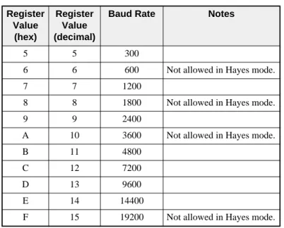
Baud Rate
The baud rates of the RS-422 port and the audio line are set in registers R[4] and R[5]. The value placed in these registers determines the baud rate. Each of these ports has a limited range of valid baud rates as displayed in Tables 3-3 and 3-4. (The Modem port is really BPS)
Table 3-3 RS-422 Port Baud Rate Table
Table 3-4 PSTN and LL Port Baud Rates
While in Multidrop mode, the line and data ports may only be set for the values in Table 3-5.
Register Value
(hex)
Register Value (decimal)
Baud Rate Notes
5 5 300
6 6 600 Not allowed in Hayes mode.
7 7 1200
8 8 1800 Not allowed in Hayes mode.
9 9 2400
A 10 3600 Not allowed in Hayes mode.
B 11 4800
C 12 7200
D 13 9600
E 14 14400
F 15 19200 Not allowed in Hayes mode.
Register Value (hex)
Register Value (decimal)
Baud Rate Modem Port Modulation
0 0 Automatic PSTN SY/MAX mode only.
5 5 300 Bell 103 FSK
7 7 1200 V.22 DPSK
9 9 2400 V.22 bis QAM
B 11 4800 V.32 QAM
C 12 7200 V.32 bis TCM (16pt)
D 13 9600 V.32 TCM (32 pt)
30 Operation 3 RM14K Manual
Table 3-5 Multidrop LL Port Baud Rates
Powering up in an illegal baud rate will cause the modem to program itself for defaults.
In Transparent mode, the line baud rate is controlled by the port baud rate register which is a PLC out-put. If a Hayes compatible AT command is received, the port and line baud rates are set to match the command, the line baud rate register is loaded with the new rate and becomes a PLC input. Switching to SY/MAX mode will return the line baud rate register to a PLC output and set the line baud rate to the line baud rate register again on the next connect. Switching to the Hayes mode will change the port register to a PLC output but the setting will stay the same until an "AT" is received.
The line baud rate setting (including the port rate register in Transparent mode) takes effect when the modem initiates a connect, either in originate or answer mode. Line rate register changes made when the modem is connected don’t take effect until the modem is disconnected and attempts to connect again. One of the implications of this is that the line rate of a remote modem may be altered and then you can hang up and call back at the new baud rate. In SY/MAX mode, the port baud rate may be changed at any time. In Transparent mode, the Port rate register may be changed by an "AT" command but only when the modem is not connected.
Phone Number Storage
Internal storage of telephone numbers is accomplished through the use of a pointer variable located in R[5]. This value corresponds to the starting register of the phone number. The value in R[5] must fall within the valid range of usable registers in the module: 10 through 2048.
The telephone number is stored in packed ASCII format of two characters per register. Only the ASCII characters 0, 1, 2, 3, 4, 5, 6, 7, 8, 9, *, #, A, B, C, D, W, [, ], T, P, R, !, ;, and the comma are valid. Any other character will act as the end of the telephone number and it is suggested that the last character of the number be followed by a 00 hex. These values are listed in Table 3-6.
The *, #, A, B, C, and D characters generate these DTMF signals. (Most telephones have the * and # keys but not the A, B, C, and D keys.) The "W" character causes the RM14K to suspend dialing until it hears the Password tone from the answering RM14K. The "[" and "]" characters are used to enclose a decimal number to indicate the next phone number to dial in an automatic call progression scheme. The "T" character selects Tone dialing while the "P" character selects Pulse dialing. (Default is "T" tone dialing.) The "R" character has the modem connect in answer (Reverse) mode. The ! character provides a 500mS hook flash. The semi-colon commands the modem to remain in command state after dialing. The "," comma character provides a pause of two seconds (Default value as set in register 8008. See Table 3-13 on page 36.).
Register Value
(hex)
Register Value (decimal)
Baud Rate Modem Port Modulation
7 7 1200 V.26 bis DPSK
9 9 2400 V.27 ter DPSK
B 11 4800 V.29 QAM (4 point)
C 12 7200 V.29 QAM (8 pt)
D 13 9600 V.29 QAM (16 pt)
RM14K Manual 3 Operation 31
Table 3-6 Dialing String Characters
For example, a long distance number requiring the area code is stored starting at R[25], (417) 555-6789, and it is required to use pulse dialing. The registers to be set would include those in Table 3-7. To dial the number the decimal value 25 would be loaded into R[5] and then Bit 1 of R[1] would be set.
Table 3-7 Phone Number Storage Example
Another example would be a local number of 555-0198 stored in the RM14K’s register R[232]. The decimal value 232 would be loaded into R[5] and then the dial command would be issued.
Table 3-8 Phone Number Storage Example 2
Phone numbers stored in registers R[10] through R[64] are non-volatile if written from the front panel and not the backplane. If these registers are written from the PLC backplane they may be cleared upon power up. For absolute non-volatile storage of numbers, use registers R[65] through R[2048].
The modem will default to the dialing type (pulse or tone) specified in the last dial command. The de-fault condition upon power up is tone dialing.
Character Description
T Dial subsequent digits DTMF. P Dial subsequent digits pulse.
, Pause for R[8008] (default 2) seconds. 0..9 Pulse or Tone digits to dial.
#,*,A,B,C,D Tone only digits to dial.
R Connect in answer (Reverse) mode. ; Remain in command state after dialing
! 500mS hook flash.
W Wait for Password tone. Time in seconds stored in R[8013]. Default = 30 seconds.
[x] Phone Number Pointer. x refers to the RM14K register for the next number to dial if the current number does not result in Carrier.
Register Value (hex)
Value (decimal)
Value (ASCII)
25 5031 20529 P1
26 3431 13361 41
27 3735 14133 75
28 3535 13621 55
29 3132 12594 12
30 3334 13108 34
31 0000 0
Register Value (hex)
Value (decimal)
Value (ASCII)
232 3535 13621 55
233 3530 13616 50
234 3139 12601 19
32 Operation 3 RM14K Manual If the phone number pointer (register 5) is zero, then any connect command (switch, dial input, register 1 bit 1) will cause the modem to go off hook in originate mode but not dial anything. If a phone num-ber is stored in registers less than 65, rememnum-ber that the PLC can overwrite these registers via the rack interface.
The RM14K is able to continually attempt to connect to a phone number, or sequence of phone num-bers with the use of the [x] characters in the dial string. The number x inside the brackets is an integer that points to the next phone number block to be dialed if the current dialing string does not result in Carrier. The number [x] may point to another phone number block, or it may point to itself.
For example, suppose an alarm relay actuates the Dial input of the RM14K. R[5] in the RM14K points to R[10] where the telephone number 5551212[20] is stored in registers R[10]...R[15]. The RM14K dials 5551212 and tries to get carrier. If the line is busy, or does not answer, then the RM14K times out and goes on-hook for one second. The RM14K then goes off-hook and attempts to dial the number that starts in R[20]. The number in R[20] could in-turn point to another phone number...etc.
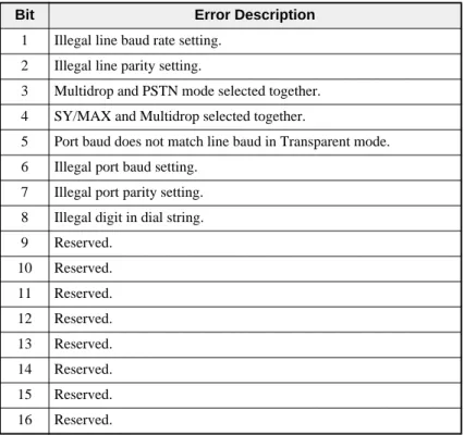
Error Register R[6]
Register R[6] is a PLC Input that provides error status of the module. This register has one bit for each error condition. When no errors are reported, this register displays the value 0. One or more bits are set on an error. Table 3-9 provides a list of the individual bits.
Table 3-9 Error Register Bit List
Rack Addressing
In order for the PLC to monitor and control the operation of the RM14K from the backplane, the RM14K must be properly rack addressed. Only Registers 1 through 64 may be rack addressed. Regis-ters above R[64] may only be accessed from the modem port or data port. When rack addressing the module, it is important to realize that R[1] in the RM14K will correspond to the first register assigned to the modem’s rack slot. For example:
An RM14K is located in slot 5 of an RRK-200 register rack. The PLC has been programmed to assign 15 PLC registers to that slot numbered R[1355] through R[1380]. These registers will correspond to R[1] through R[25] in the RM14K. See Table 3-10.
Bit Error Description
1 Illegal line baud rate setting. 2 Illegal line parity setting.
3 Multidrop and PSTN mode selected together. 4 SY/MAX and Multidrop selected together.
5 Port baud does not match line baud in Transparent mode. 6 Illegal port baud setting.
7 Illegal port parity setting. 8 Illegal digit in dial string. 9 Reserved.
10 Reserved. 11 Reserved. 12 Reserved. 13 Reserved. 14 Reserved. 15 Reserved. 16 Reserved.
RM14K Manual 3 Operation 33 Notice that for the Processor to set the pointer to the phone number via the backplane, it needs to write to R[1359]. If an external source were to read this value from the modem’s port, it would read R[5]. As in the above example, the user does not have to rack address all of the 64 available registers. Regis-ters 16 through 64 are still available for mailbox use from the modem ports, just like R[65] through R[2048]. In some cases, it may not be necessary to rack address the modem at all thus limiting the available methods for controlling the modem to the front panel switches, and through serial communi-cation commands.
I/O Direction
Registers 10 through 64 default to PLC outputs (Status Register = A000 hex). These registers remain PLC outputs until they are written to by an external device via the RS-422 port or the Line port. At this point, the register changes to a PLC input (Status Register = E000 hex) and the PLC may no longer write data to this register.
Register 1 is always a PLC output. Register 2 is always a PLC input. Register 3 and 4 are usually PLC outputs, but this may change during Transparent operation. Registers 5 and 7 default to output, but may be changed to input with an external write. (Like R[10] through R[64]) Registers 6 and 8 are always PLC inputs. Register 9 is reserved for future use.
Table 3-10 Rack Addressing Example
Configuration in SY/MAX Mode
The RM14K in SY/MAX mode may be configured from an external source capable of generating SY/MAX protocol network READs and WRITEs. This type of equipment includes: Processors, D-LOG modules, UCM modules, personal computers, SPE4 and EPE5 modules, and other computers. To modify the configuration simply write to the appropriate register within the module. The most conven-ient method of configuration is using the RM14KSW software on an IBM compatible personal com-puter.
To access the RM14K in SY/MAX mode the use of special route numbers is required.
PLC Register RM14K Register Function
1355 1 Command Bits
1356 2 Status Bits
1357 3 Port Baud Rate
1358 4 Line Baud Rate
1359 5 Pointer to Phone #
1360 6 Error Register
1361 7 Password
1362 8 Last Password Received
1363 9 Reserved
1364 10 General Purpose
1365 11 General Purpose
1366 12 General Purpose
1367 13 General Purpose
1368 14 General Purpose
34 Operation 3 RM14K Manual
Drop 201
If the last drop in the route of a SY/MAX packet arriving at an RM14K’s RS-422 port is 201, the mo-dem will operate on that packet. All other routes will be passed out the line port and ignored by the modem.
Drop 202
If the last drop in the route of a SY/MAX packet arriving at an RM14K’s line port is 202, the modem will operate on that packet. All other routes will be passed out the RS-422 port and ignored by the modem.
Drop 206
If the last drop in the route of a SY/MAX packet arriving at an RM14K is 206, the modem will look at the next to last drop number and decrement that number if it is greater than 1. If the next to last drop number is one, then the modem will operate on that packet. This technique allows downstream RM14Ks to be reached through multiple RM14K hops.
To reach the fifth RM14K in the network, simply route to the RM14K with the normal route and have the next to last drop be 5 and the last drop number be 206.
Configuration in Transparent Mode
In SY/MAX mode, the modem differentiates between commands and data by the route field. Routes terminating in drop 20, 202, or 206 are processed by the modem as commands, all other routes are con-sidered data and passed through.
In Hayes mode, the modem differentiates between commands and data by assuming two states, data and command. In data state, it is a transparent modem and any bytes received on the serial port are trans-mitted to the line. In command state, the modem accepts a string of single letter commands. The com-mand string must begin with the attention code "AT". When not connected, the modem is always in command state and uses the "AT" character pair to determine the baud rate of the host device and set itself to the same baud setting. The modem can be switched from command state to data state by dial-ing (unless the dial strdial-ing includes the ; character), answerdial-ing either manually with the ATA command or automatically, or with the ATO command from the connected state only. The modem is switched from the data state to the command state by loss of carrier or, when connected, by an escape sequence of three of the characters specified by S2. For the escape sequence to be recognized, it must be pre-ceded by a guard time during which nothing is received on the serial port. The guard time is a mini-mum of S12 * 20mS. The maximini-mum elapsed time between the first and third escape characters is also S12 * 20mS. In the connected command state (reached from connected state by the escape sequence), the automatic baud rate detection is not operative and the commands must be issued at the rate estab-lished when the connection was made.
AT Commands (PSTN mode only)
The incoming AT characters should be of the same case for proper automatic baud rate and parity deter-mination.
As described above, the RM14K in Transparent Mode may be configured by the use of ASCII Hayes AT commands through the RS-422 port. The RM14K must be in Command mode (Not Connect mode) to accept Hayes AT commands. The modem is in the Command mode when it is on hook. If the mo-dem is off hook and has carrier then it is in the Connect mode and all incoming characters are transmit-ted out the modem port. To change from Connect to Command mode the following procedure is used: 1 Create a one second delay after any characters previously transmitted.
2 Send the modem +++
3 Create another one second delay before any subsequent characters are transmitted. The modem will then be ready to accept AT commands.
RM14K Manual 3 Operation 35 The RM14K will accept the AT commands listed in Table 3-11.
Table 3-11 Hayes Command List
Dialing String Characters
The dial string (including the stored packed ASCII strings) may include the following characters listed in Table 3-12.
Table 3-12 Dialing String Characters
AT Command Description Notes
A Answer ATDT14175551234
Cn Squelch Transmit carrier squelch if n = 0.
D... Dial
En Echo Command state echo. Echo if n <> 0.
Hn Hookswitch Valid only in PSTN mode. Off Hook if n <> 0.
H Hangup Valid only in PSTN mode.
Ln Volume L0 = low (Ln valid in PSTN mode only.) L1 = medium
L2 = loud (Default).
Mn Speaker Control M0 = Speaker always OFF. (Mn valid in PSTN mode only.) M1 = Speaker only on through dial and handshake. (Default) M2 = Speaker always ON.
M3 = Speaker only on through handskake. O Return to Connect Returns to online after +++ or dialing with ; Qn Quiet Result message quiet mode. Quiet if n <> 0.
R Reverse Connect in answer (Reverse) mode. Sn? Read ’S’ register
Sn=m Write ’S’ register
Vn Vervbose Numeric codes if n = 0.
W Wait Wait for Password Tone before proceeding. Xn Result codes Ignored. Modem is always X0.
Z Reset to Factory Resets modem to factory defaults. A/ Repeat last
command
Not supported at this time. AX SY/MAX Switches back to SY/MAX mode.
Character Description
T Dial subsequent digits DTMF. P Dial subsequent digits pulse. , Pause for S8 (default 2) seconds. 0..9 Pulse or Tone digits to dial. #,*,A,B,C,D Tone only digits to dial.
R Connect in answer (Reverse) mode. W Wait for the Password Tone.
; Remain in command state after dialing
36 Operation 3 RM14K Manual
S Registers
In addition to the AT commands, the RM14K also supports several S registers. These registers are also located in the internal SY/MAX registers 8000...8012. Table 3-13 lists the available S registers.
Table 3-13 "S" Register List
In the RM14K, unlike common Hayes type modems, all S register settings and modes (ATV, ATQ, ATE) are non-volatile. For this reason, there is no AT&W command to "write setup to nonvolatile memory". The ATZ command resets the modem to factory defaults just like the CLEAR push-button on the PC board except that the ATZ leaves the modem in Hayes mode and the CLEAR button puts it in SY/MAX mode.
Front Panel Control Inputs
The RM14K has a number of alternate control inputs available from the front panel for manual control. These include three double throw, spring loaded center off, toggle switches and a voltage sensing input. These switches may be disabled by setting Options bit 4 of register 2054.
Hayes Switch
The top toggle switch controls the mode of the modem to be in either Transparent (Hayes) or SY/MAX mode. When the switch is toggled toward the Hayes label, the modem will enter Transparent mode. The Status register R[2] will SET bit 4 to indicate that Transparent mode has been selected.
"S" Register
SY/MAX Register
Description Default Value (decimal)
0 8000 Number of rings to answer on. Auto Answer can be enabled from the front panel or SY/MAX command register even if this register is zero.
3
1 8001 Ring detect counter. Works even if Auto Answer is disabled.
0
2 8002 Escape code character. 43
3 8003 Carriage Return character. 13
4 8004 Line feed character. 10
5 8005 Backspace character. 8
6 8006 Wait for dial tone. To comply with FCC rules, the modem won’t wait less than 2 seconds regardless.
2 7 8007 Time in seconds to wait (after dialing or answering) for
carrier.
30 8 8008 Duration in seconds for comma pause in dial string. 2 9 8009 Carrier Detect response time. (1/10 second unit) 6 10 8010 Delay between loss of carrier and hang up. (1/10 S) 14
11 8011 DTMF burst length in mS. 95
12 8012 Escape code guard time in 20mS units. 50
13 8013 Maximum duration in seconds for "W" command in dial string.
30 14 8014 Time in seconds to wait for proper password after
sending password tone.