Juniper Networks, Inc. 1194 North Mathilda Avenue Sunnyvale, CA 94089 USA 408 745 2000 or 888 JUNIPER www.juniper.net
Part Number : 200011-002 06/01
Voice over IP Solutions
Sean Christensen
Professional Services
Executive Summary . . . 5
Perspective . . . 5
Legacy Voice Services . . . 6
VoIP Functions . . . 9
Signaling . . . 9
Database Services . . . 9
Call Connect and Disconnect (Bearer Control) . . . 9
CODEC Operations . . . 9
VoIP Components . . . 11
Media Gateways . . . 11
Media Gateway Controllers . . . 11
IP Network . . . 12
Voice Protocols and Usages . . . 14
Signaling System Seven . . . 14
H.323 . . . 15
Real-time Transport Protocol . . . 17
Real-time Transport Control Protocol . . . 18
Media Gateway Control Protocol . . . 18
Session Initiation Protocol . . . 19
Signaling Transport . . . 21
Megaco/H.248 . . . 22
Resource Reservation Protocol . . . 22
VoIP Service Considerations . . . 23
Latency . . . 23
Jitter . . . 24
Bandwidth . . . 25
Packet Loss . . . 26
Reliability . . . 27
Security . . . 27
Juniper Networks VoIP Network Solutions . . . 28
High-speed Interfaces . . . 28
Predictable Performance . . . 28
Class of Service . . . 29
CoS Application . . . 31
Example CoS Configuration . . . 32
Low Latency Design . . . 35
Predictable and Minimal Jitter . . . 36
Per-flow Load Balancing . . . 36
MPLS . . . 37
MPLS Traffic Engineering . . . 38
Figure 1: Basic Flow of Traditional PSTN and SS7 Network . . . 8
Figure 2: Full Service VoIP Network . . . 13
Figure 3: SS7 Protocol Stack . . . 15
Figure 4: Example H.323 Call Process . . . 16
Figure 5: Upper Layers of the RTP Protocol . . . 17
Figure 6: MGCP Functions . . . 19
Figure 7: SIP Proxy Operation . . . . 20
Figure 8: SIP Redirector Server . . . 21
Figure 9: Example Jitter . . . 25
Figure 10: Juniper Networks Class of Service . . . 29
Figure 11: Juniper Networks Class-of-service Default . . . 32
Figure 12: Example Multiservice Network . . . 32
Figure 13: Example Mapping of Services to Output Queues . . . 34
Figure 14: Logical View of Packet Forwarding Engine . . . 36
Figure 15: Example Flow in an MPLS Network . . . 38
Figure 16: MPLS Traffic Engineering Efficiently Uses Bandwidth . . . 39
Figure 17: Full-duplex LSPs for Voice and Data Traffic . . . 40
Figure 18: Virtual Router Redundancy Protocol . . . 43
Table 1: ITU Encoding Standards . . . 10 Table 2: Example Queue Configuration . . . 33
Although voice over IP (VoIP) has been in existence for some years, service demands are forcing a rapid evolution of the technology. The pace of service integration (convergence) with new and existing networks continues to increase as VoIP products and services develop. Also, the promise of broadband services and the integration of voice and data at all levels further the need for VoIP applications.
Critical to success is the ability to deploy value-added and high-margin services. VoIP and other IP-based technologies are best positioned to be the solution to realize these more profitable services. For example, you could deploy a unified messaging system that would voice synthesize e-mails over a phone to the subscriber.
Though VoIP is still evolving, packet-based telephony is becoming more advanced. Voice protocols have further developed to offer a richer set of features, scalability, and
standardization than what was available only a few years ago. Today, Juniper Networks, Inc. has solutions that enable you to deploy reliable, high-performance networks that support VoIP services. Juniper Networks® solution translates into lower maintenance costs by using a common, ubiquitous network to provide any number of services. Instead of deploying discreet, separate services, each with its own physical and maintenance overhead, you can deploy a common IP backbone to provide the needed transport.
Perspective
Several factors drive VoIP application development and deployment. One obvious reason is that of economics. Currently, increased competition amongst existing and emerging voice service vendors has brought tremendous downward pressure in the cost of voice services in the telecommunications market. This trend is likely to continue to accelerate the drop in voice service prices.
Service providers, competitive local exchange carriers (CLECs), and telecommunications providers alike are deploying VoIP.
■ Many existing service provider networks support mostly data (Internet) services that are
based on IP. These service providers already own and are further deploying IP
infrastructures. Service providers wanting to enter the voice services market will transport voice traffic across these existing IP backbones. Building a parallel voice services network based on legacy circuit-switching equipment is simply not a cost-effective option.
■ Many emerging CLECs are sensitive to the cost of developing voice service networks. For
many, the cost of legacy circuit-switching equipment is prohibitively high. Also the costs of space, personnel, and operations in maintaining such networks are unacceptable. These carriers also need a network that they can leverage to realize other data services, such as Internet, virtual private networks (VPNs), and managed network offerings. For this group, VoIP is an ideal solution to deploy voice services.
■ Major telecommunications providers are looking for ways to cut the cost of running and upgrading existing voice networks. These carriers want to replace and augment their existing networks with VoIP solutions for similar reasons. Another issue they face is the state of existing tariff regulations. Major carriers can use data services to transport their voice calls to get around traditional (regulated) pricing structures and reduce the total cost of a phone call.
In addition to cost advantages, VoIP services have compelling technical advantages over circuit switching. VoIP networks are based more on an open architecture than that of their
circuit-switched contemporaries. This open, standards-based architecture means that VoIP services are more interchangeable and more modular than that of a proprietary, monolithic voice switch. You can now select best-in-class products without being tied to one specific vendor. Open standards also translates into the realization of new services that you can rapidly develop and deploy rather than waiting for a particular vendor to develop a proprietary solution. Moreover, VoIP is suitable for CTI (Computer Telephony Integration) and other next-generation applications, which is insightful when looking to future networks that provide enhanced services.
Legacy Voice Services
Understanding how the public switched telephone network (PSTN) function is useful for discussions on VoIP technology. Hence, this section briefly describes how the current PSTN works.
There are four major tasks the PSTN must perform to connect a call. Although there are other services besides an end-to-end voice call (for example, conference calls and other services), they are based on the following requirements.
■ Signaling
■ Database services
■ Call connect and tear-down
■ Voice to digital conversion
Phone calls are inherently connection-oriented. That is, the connection to the called person must be established ahead of time before the conversation can occur. Switches, the central components in a PSTN, are responsible for creating this connection. Between the circuit switches are connections (trunk links) that carry the voice traffic. These links vary in speed from T1 and E1 to OC-192c/STM-64, with individual channels (DS-0s) in each link type representing one voice channel. Switches are also responsible for converting the analog signal (voice) to a digital format that is transported across the network.
Signaling notifies both the network and its users of important events. Examples of signaling range from the ringer activation letting you know that a call is coming, to the dialing of digits used to make a call. Network elements also use signaling to create connections through a network.
The Signaling System Seven (SS7) network is a packet-based (connectionless) network that transports the signaling traffic between the switches involved in the call. The service control points (SCPs) are the databases that execute the queries to translate phone numbers into circuit-switching details. They also make it possible for such features as 800 number support,
Generally, the SS7 control network is out of band (not included) with the same links used to carry the actual voice channels. Specialized equipment called signal transfer points (STPs) transport the signaling messages. These STPs are analogous to IP routers in that the messages are carried in packets called the message transfer parts (MTPs).
The SS7 network is quite extensive (a large collection of networks) and is deployed throughout most of the developed world. There are many technical and historical reasons why the signaling portion of the network is broken out from the rest of the system. However, the greatest value in such a design is to enable you to add network intelligence and features without a dependency on the underlying circuit-switching infrastructure.
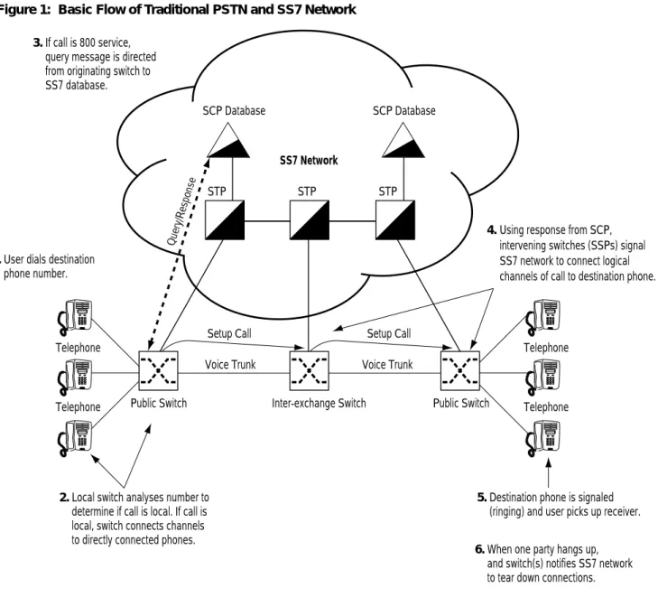
When someone picks up the phone receiver, the public switch is alerted and prepares for the phone number digits to be dialed. This phone switch might be a private branch exchange (PBX) in the same building as the phone or a public switch that is miles away. As the digits are dialed, the originating switch analyzes the digits to see if they are valid and if the destination phone is connected to this same switch. If the call is a local call (not outside the exchange), the switch connects the logical channels of the phones involved and the call is completed.
If the call is not local (for example, an 800 number), the originating switch directs a message to a database. Note the query might not be resolved directly by any particular database and that other provider databases might resolve the requested connection. The initial query results in the intervening switches connecting the logical channels that lead to the destination phone. The destination switch signals the destination phone by activating the ringer. The called party has the option to answer the phone and complete the connection.
When the conversation takes place, the switches at this point must be able to convert the voice (analog signal) into a digital form for transport over the network. Once the call is completed, the switches notify the rest of the network to tear down the connections. There are many more details to this transaction; however, these steps describe the basic flow of events in completing a call (Figure 1). In addition, there are a great many supervisory messages that are passed along the network, such as ringing indication, busy signal, and hang up.
Figure 1: Basic Flow of Traditional PSTN and SS7 Network 3.If call is 800 service,
query message is directed from originating switch to SS7 database.
1.User dials destination phone number.
2.Local switch analyses number to determine if call is local. If call is local, switch connects channels to directly connected phones.
6.When one party hangs up, and switch(s) notifies SS7 network to tear down connections. 5.Destination phone is signaled
(ringing) and user picks up receiver.
SS7 Network
STP STP STP
Query/Response
Public Switch Inter-exchange Switch Public Switch
Telephone
Telephone
Telephone
Telephone
Voice Trunk Voice Trunk
SCP Database SCP Database
Setup Call Setup Call
4. Using response from SCP, intervening switches (SSPs) signal SS7 network to connect logical channels of call to destination phone.
VoIP Functions
VoIP components must be able perform the same features as the PSTN network.
■ Signaling
■ Database services
■ Call connect and disconnect (bearer control)
■ CODEC operations
Signaling
Signaling in a VoIP network is just as critical as it is in the legacy phone system. The signaling in a VoIP network activates and coordinates the various components to complete a call. Although the underling nature of the signaling is the same, there are some technical and architectural differences in a VoIP network.
Signaling in a VoIP network is accomplished by the exchange of IP datagram messages between the components. The format of these messages is covered by any number of standard protocols. Regardless of which protocol and product suites that are used, these message streams are critical to the function of a voice-enabled network and might need special treatment to guarantee their delivery.
Database Services
Database services are a way to locate an endpoint and translate the addressing that two (usually heterogeneous) networks use. For example, the PSTN uses phone numbers to identify endpoints, while a VoIP network could use an IP address (address abstraction could be accomplished with DNS) and port numbers to identify an endpoint. A call control database contains these mappings and translations. Another important feature is the generation of transaction reports for billing purposes. You can employ additional logic to provide network security, such as to deny a specific endpoint from making overseas calls on the PSTN side. This functionality, coupled with call state control, coordinates the activities of the elements in a VoIP network.
Call Connect and Disconnect (Bearer Control)
The connection of a call is made by two endpoints opening communications sessions between each other. In the PSTN, the public (or private) switch connects logical DS-0 channels through the network to complete the calls. In a VoIP implementation, this connection is a multimedia stream (audio, video, or both) transported in real time. This connection is the bearer channel and represents the voice or video content being delivered. When communication is complete, the IP sessions are released and optionally network resources are freed.
CODEC Operations
Voice communication is analog, while data networking is digital. The process of converting analog waveforms to digital information is done with a coder-decoder (CODEC, which is also known as a voice coder-decoder [VOCODER]). There are many ways an analog voice signal can be transformed, all of which are governed by various standards. The process of conversion is complex and beyond the scope of this paper. Suffice to say that most of the conversions are
In addition to performing the analog to digital conversion, CODECs compress the data stream, and provide echo cancellation. Compression of the represented waveform can afford you bandwidth savings. The bandwidth savings for the voice services can come in several forms and work at different levels. For example, analog compression can be part of the encoding scheme (algorithm) and does not need further digital compression from the higher working layers of the media gateway application. Another way to save bandwidth is the use of silence suppression, which is the process of not sending voice packets between the gaps in human conversations.
Using compression and/or silence suppression can result in sizable bandwidth savings. However, there are some applications that could be adversely affected by compression. One example is the impact on modem users. Compression schemes can interfere with the
functioning of modems by confusing the constellation encoding used. The result could be modems that never synchronize or modems that exhibit very poor throughput. Some gateways might implement some intelligence that can detect modem usage and disable compression. Another potential issue deals with low-bit-rate speech compression schemes, such as G.729 and G.723.1. These encoding schemes try to reproduce the subjective sound of the signal rather than the shape of the waveform. A greater amount of packet loss or severe jitter is more noticeable than that of a non-compressed waveform. However, some standards might employ interleaving and other techniques that can minimize the effects of packet loss.
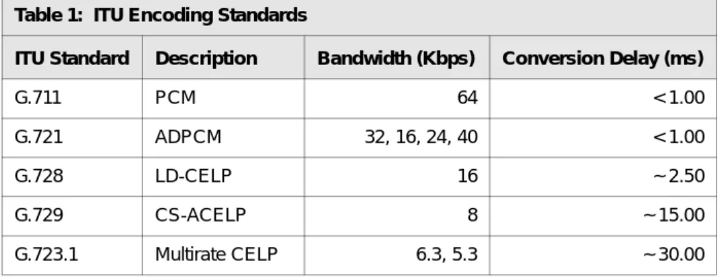
The output from the CODECs is a data stream that is put into IP packets and transported across the network to an endpoint. These endpoints must use the standards, as well as a common set of CODEC parameters. The result of using different standards or parameters on both ends is unintelligible communication. Table 1 lists some of the more important encoding standards covered by the International Telecommunications Union (ITU). As you can see, there is a price paid for reduced bandwidth consumption by increased conversion delay.
Table 1: ITU Encoding Standards
ITU Standard Description Bandwidth (Kbps) Conversion Delay (ms)
G.711 PCM 64 < 1.00
G.721 ADPCM 32, 16, 24, 40 < 1.00
G.728 LD-CELP 16 ~ 2.50
G.729 CS-ACELP 8 ~ 15.00
VoIP Components
The major components of a VoIP network are very similar in functionality to that of a circuit-switched network. VoIP networks must perform all of the same tasks that the PSTN does, in addition to performing a gateway function to the existing public network. Although using different technology and approach, some of the same component concepts that make up the PSTN also create VoIP networks. There are three major pieces to a VoIP network.
■ Media gateways
■ Media gateway / signaling controllers
■ IP network
Media Gateways
Media gateways are responsible for call origination, call detection, analog-to-digital conversion of voice, and creation of voice packets (CODEC functions). In addition, media gateways have optional features, such as voice (analog and/or digital) compression, echo cancellation, silence suppression, and statistics gathering.
The media gateway forms the interface that the voice content uses so that it can be transported over the IP network. Media gateways are the sources of bearer traffic. Typically, each
conversation (call) is a single IP session transported by a Real-time Transport Protocol (RTP) that runs over UDP.
Media gateways exist in several forms. For example, media gateways could be a dedicated telecommunication equipment chassis, or even a generic PC running VoIP software. Their features and services can include some or all of the following.
■ Trunking gateways that interface between the telephone network and a VoIP network. Such
gateways typically manage a large number of digital circuits.
■ Residential gateways that provide a traditional analog interface to a VoIP network.
Examples of residential gateways include cable modem/cable set-top boxes, xDSL devices, and broadband wireless devices.
■ Access media gateways that provide a traditional analog or digital PBX interface to a VoIP
network. Examples include small-scale (enterprise) VoIP gateways.
■ Business media gateways that provide a traditional digital PBX interface or an integrated
soft PBX interface to a VoIP network.
■ Network access servers that can attach a modem to a telephone circuit and provide data
access to the Internet.
■ Discreet IP telephones units.
Media Gateway Controllers
Media gateway controllers house the signaling and control services that coordinate the media gateway functions. Media gateway controllers could be considered similar to that of H.323 gatekeepers. The media gateway controller has the responsibility for some or all of the call signaling coordination, phone number translations, host lookup, resource management, and signaling gateway services to the PSTN (SS7 gateway). The amount of functionality is based on the particular VoIP enabling products used.
In a scalable VoIP network, you can breakup the role of a controller into signaling gateway controller and media gateway controller. For calls that originate and terminate within the domain of the VoIP network, only a media gateway controller might be needed to complete calls. However, a VoIP network is frequently connected to the public network. You could use a signaling gateway controller to directly connect to the SS7 network, while also interfacing to the VoIP network elements. This signaling controller would be dedicated to the message translation and signaling needed to bridge the PSTN to the VoIP network.
The services of these devices are defined by the protocols and software they are running. There are several protocols and implementations that any number of vendors could deploy. Knowing the details of how the devices use their suite of protocols is important to designing the IP backbone that is to service the VoIP elements.
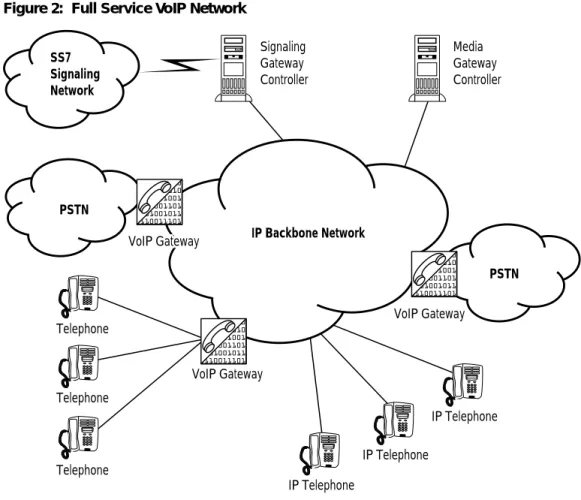
IP Network
You can view the VoIP network as one logical switch. However, this logical switch is a distributed system, rather than that of a single switch entity; the IP backbone provides the connectivity among the distributed elements. Depending on the VoIP protocols used, this system as a whole is sometimes referred to as a softswitch architecture.
Figure 2: Full Service VoIP Network
The IP infrastructure must ensure smooth delivery of the voice and signaling packets to the VoIP elements. Due to their dissimilarities, the IP network must treat voice and data traffic differently. If an IP network is to carry both voice and data traffic, it must be able to prioritize the different traffic types.
There are several correlations to the VoIP and circuit-switching components, however there are many differences. One is in the transport of the resulting voice traffic. Circuit-switching telecommunications can be best classified as a TDM network that dedicates channels, reserving bandwidth as it is needed out of the trunk links interconnecting the switches. For example, a phone conversation reserves a single DS-0 channel, and that end-to-end connection is used only for the single conversation.
IP networks are quite different from the circuit-switch infrastructure in that it is a
packet-network, and it is based on the idea of statistical availability. Class of service (CoS) ensures that packets of a specific application are given priority. This prioritization is required for real-time VoIP applications to ensure that the voice service is unaffected by other traffic flows.
Telephone
Telephone
Telephone
IP Telephone
IP Telephone
IP Telephone Media Gateway Controller Signaling
Gateway Controller
VoIP Gateway VoIP Gateway
VoIP Gateway VoIP Gateway
VoIP Gateway SS7
Signaling Network
PSTN
PSTN IP Backbone Network
Voice Protocols and Usages
There are a variety of VoIP products and implementations with a wide range of features that are currently deployed. Two major standards bodies govern multimedia delivery (voice being one type) over packet-based networks: ITU and Internet Engineering Task Force (IETF). Some of the implementations are focused on the ITU specifications more than that of the IETF standards. Also, because of the overlap and co-development in many of the standards, there are implementations from both groups of technologies. Still, some vendors are implementing proprietary schemes that fill apparent gaps in the standards or add functionality that is product dependent.
However, not all the standards fall all into one or the other group; many of the standards in both bodies are based on solving the same problems. The result is some overlap of
functionality, as well as differences in approach and nomenclature.
Several VoIP protocols and options exist, such as described in the following sections. Not all of the protocols are used in one specific product group. Instead, the product vendor will code its offerings with what is most applicable for its, scope, services, and market.
Each of these protocols has its own strengths and weaknesses with a different approach to service delivery. Each of these protocols is successful in different products having a specific market focus. Those protocols listed in this section are not exhaustive; there are a few other protocol options available.
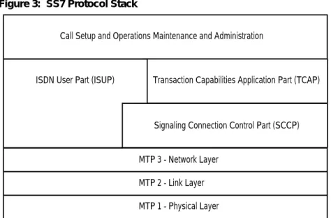
Signaling System Seven
SS7 (Figure 3) is a widely used suite of telephony protocols expressly designed to establish and terminate phone calls. The SS7 signaling protocol is implemented as a packet-switched network. SS7 networks are intended to be out-of-band from that of the voice network itself. SS7 is both the protocol and the network designed to signal voice services. The importance of the system is that it is a unified interface for the establishment of circuit-switching, translation, and transaction (billing) services.
Figure 3: SS7 Protocol Stack
SS7 is not built on top of other protocols; rather, it is completely its own protocol suite from physical to application layers. For networks transporting SS7, it is important that these services are ether translated or tunneled through the IP network reliably. Given the importance of SS7 signaling, it is necessary to ensure that these messages are given priority in the network. VoIP networks might need access to the SS7 facilities to conduct calls that are bridged to the legacy telephony (PSTN) system. How much access is decided by the robustness of the service deployed. Generally, you might need to plan for some amount of SS7 integration to deploy even the most basic of phone services.
H.323
The ITU recommendation H.323 is a packet-based multimedia communication system that is a set of specifications. These specifications define various signaling functions, as well as media formats related to packetized audio and video services.
H.323 standards were generally the first to classify and solve multimedia delivery issues over LAN technologies. However, as IP networking and the Internet became prevalent, many Internet RFC standard protocols and technologies were developed and based on some of the previous H.323 ideas. Today there is co-operation between the ITU and IETF in solving existing problems, but it is fair to say that the RFC process of furthering the standards has had greater success than the H.323 counterparts.
H.323 networks consist of (media) gateways and gatekeepers. Gateways serve as both H.323 termination endpoint and interface with non-H.323 networks, such as the PSTN. Gatekeepers function as a central unit for call admission control, bandwidth management, and call signaling. A gatekeeper and all its managed gateways form an H.323 zone. Although the gatekeeper is not a required element in H.323, it can help H.323 networks to scale to a larger size by separating call control and management functions from the gateways.
H.323 specifications tend to be heavier and with an initial focus in LAN networking. These standards have some shortcomings in scalability, especially in large-scale deployments. One of
Call Setup and Operations Maintenance and Administration
ISDN User Part (ISUP) Transaction Capabilities Application Part (TCAP)
Signaling Connection Control Part (SCCP)
MTP 3 - Network Layer MTP 2 - Link Layer MTP 1 - Physical Layer
overhead involved. However, note that most H.323 scalability limitations are based on the prevalent version two of the specification. Subsequent versions of H.323 have a focus on solving some of these problems.
With each call that is initiated, a TCP session (H.225.0 protocol) is created using an encapsulation of a subset of Q.931 messages. This TCP connection is maintained for the duration of the call.
A second session is established using the H.245 protocol. This TCP-based process is for capabilities exchange, master-slave determination, and the establishment and release of media streams. This group of procedures is in addition to the H.225.0 processes.
The H.323 quality of service (QoS) delivery mechanism of choice is the Resource Reservation Protocol (RSVP). This protocol is not considered to have good scaling properties due to its focus and management of individual application traffic flows.
Although H.323 many not be well suited in service provider spaces, it is well positioned for deployment of enterprise VoIP applications. As a service provider, you might find it necessary to bridge, transport, or interface H.323 services and applications to the PSTN.
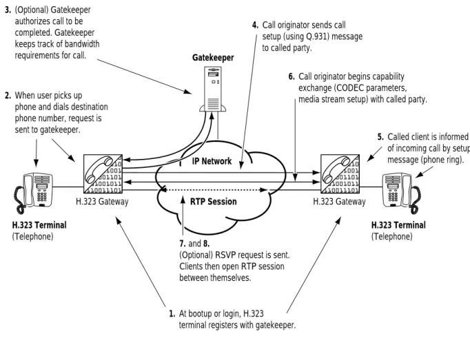
Figure 4: Example H.323 Call Process
H.323 Terminal (Telephone)
H.323 Terminal (Telephone) Gatekeeper
IP Network
RTP Session
1. At bootup or login, H.323 terminal registers with gatekeeper. 2. When user picks up
phone and dials destination phone number, request is sent to gatekeeper. 3. (Optional) Gatekeeper
authorizes call to be completed. Gatekeeper keeps track of bandwidth requirements for call.
4. Call originator sends call setup (using Q.931) message to called party.
5. Called client is informed of incoming call by setup message (phone ring). 6. Call originator begins capability
exchange (CODEC parameters, media stream setup) with called party.
7.and 8.
(Optional) RSVP request is sent. Clients then open RTP session between themselves.
Real-time Transport Protocol
RFC 1889 and RFC 1890 cover the RTP, which provides end-to-end delivery services for data with real-time characteristics, such as interactive audio and video. Services include payload type identification, sequence numbering, time stamping, and delivery monitoring.
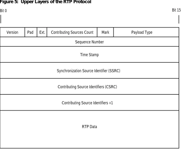
The RTP protocol (Figure 5) provides features for real-time applications, with the ability to reconstruct timing, loss detection, security, content delivery and identification of encoding schemes. The media gateways that digitize voice use the RTP protocol to deliver the voice (bearer) traffic. For each participant, a particular pair of destination IP addresses defines the session between the two endpoints, which translates into a single RTP session for each phone call in progress.
Figure 5: Upper Layers of the RTP Protocol
RTP is an application service built on UDP, so it is connectionless with best-effort delivery. Although RTP is connectionless, it does have a sequencing system that allows for the detection of missing packets.
As part of its specification, the RTP Payload Type field includes the encoding scheme that the media gateway uses to digitize the voice content. This field identifies the RTP payload format and determines its interpretation by the CODEC in the media gateway. A profile specifies a default static mapping of payload type codes to payload formats. These mappings represent the ITU G series of encoding schemes.
Version Pad Ext. Contributing Sources Count Mark Payload Type
Sequence Number
Time Stamp
Contributing Source Identifiers (CSRC)
Contributing Source Identifiers +1
RTP Data
Synchronization Source Identifier (SSRC)
With the different types of encoding schemes and packet creation rates, RTP packets can vary in size and interval. You must take RTP parameters into account when planning voice services. All the combined parameters of the RTP sessions dictate how much bandwidth is consumed by the voice bearer traffic. RTP traffic that carries voice traffic is the single greatest contributor to the VoIP network load.
Real-time Transport Control Protocol
Real-time Transport Control Protocol (RTCP) is the optional companion protocol to RTP; it is not needed for RTP to work. The primary function of RTCP is to provide feedback on the quality of the data distribution being accomplished by RTP. This function is an integral part of the RTP's role as a transport protocol and is related to the flow and congestion control
functions of the network. Although the feedback reports from RTCP do not tell you where problems are occurring (only that they are), they can be used as a tool to locate problems. With the information generated from different media gateways in the network, RTCP feedback reports enable you to evaluate where network performance might be degrading.
RTCP enables you to monitor the quality of a call session by tracking packet loss, latency (delay), jitter, and other key VoIP concerns. This information is provided on a periodic basis to both ends and is processed per call by the media gateways.
Some gateway devices might not employ RTCP because the facility to report such information is not applicable to the end user. For example, a single residential user (with an analog phone) might not have access to the gateway providing the service. Also, the media gateway vendor can use a more scalable approach of tracking call quality statistics. In this case, the storage, transport and presentation of statistical info are device dependent.
If using RTCP (or a vendor specific implementations) in the network, take into account bandwidth calculations for the protocol. You need to limit the control traffic of RTCP to a small and known fraction of the session bandwidth. It should be small so as not to impair the ability of the transport protocol to carry data. Investigate the amount of bandwidth needed so that you can include the control traffic in the bandwidth specification. RFC specifications recommend that the fraction of the session bandwidth allocated to RTCP be fixed at five percent of RTP traffic.
Media Gateway Control Protocol
The Media Gateway Control Protocol (MGCP, RFC 2705) follows more of the softswitch architecture philosophy. It breaks up the role of traditional voice switches into the components of media gateway, media gateway controller, and signaling gateway functional units. This facilitates the independent managing of each VoIP gateway as a separate entity.
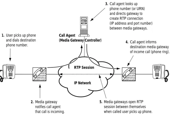
MGCP is a master-slave control protocol that coordinates the actions of media gateways (Figure 6). The media gateway controller in MGCP nomenclature is sometimes referred to as a call agent. The call agent manages the call-related signaling control intelligence, while the media gateway informs the call agent of service events. The call agent instructs the media gateway to create and tear down connections when the calls are generated. In most cases, the call agent informs the media gateways to start an RTP session between two endpoints.
Figure 6: MGCP Functions
The signaling performed by the call agent and gateways is in the form of structured messages inside UDP packets. The call agent and media gateways have retransmission facilities for these messages; however, the MGCP itself is stateless. Hence, messages are timed out by the VoIP components if a message is lost. (Compare this mechanism to a TCP delivery mechanism where the protocol attempts to retransmit in the case of packet loss.) Therefore, it is important that you treat MGCP messages with greater priority over that of non-real-time so that packet loss does not equate to service interruptions.
Session Initiation Protocol
The Session Initiation Protocol (SIP, RFC 2543) is part of IETF's multimedia data and control protocol framework. SIP is a powerful client-server signaling protocol used in VoIP networks. SIP handles the setup and tear down of multimedia sessions between speakers; these sessions can include multimedia conferences, telephone calls, and multimedia distribution.
SIP is a text-based signaling protocol transported over either TCP or UDP, and is designed to be lightweight. It inherited some design philosophy and architecture from the Hypertext Transfer Protocol (HTTP) and Simple Mail Transfer Protocol (SMTP) to ensure its simplicity, efficiency and extensibility.
SIP uses invitations to create Session Description Protocol (SDP) messages to carry out
capability exchange and to setup call control channel use. These invitations allow participants Call Agent
(Media Gateway Controller)
IP Network RTP Session 1. User picks up phone
and dials destination phone number.
2. Media gateway notifies call agent that call is incoming.
3. Call agent looks up phone number (or URN) and directs gateway to create RTP connection (IP address and port number) between media gateways.
4. Call agent informs destination media gateway of income call (phone ring).
5. Media gateways open RTP session between themselves when called user picks up phone.
SIP supports user mobility by proxying and redirecting requests to the user's current location. Users can inform the server of their current location (IP address or URL) by sending a
registration message to a registrar. This function is powerful and often needed for a highly mobile voice user base.
The SIP client-server application has two modes of operation; SIP clients can ether signal through a proxy or redirect server.
■ Using proxy mode (Figure 7), SIP clients send requests to the proxy, and the proxy ether
handles requests or forwards them on to other SIP servers. Proxy servers can insulate and hide SIP users by proxying the signaling messages. To the other users on the VoIP network, the signaling invitations look as if they are coming from the proxy SIP server.
Figure 7: SIP Proxy Operation
IP Telephone (SIP client) [email protected]
IP Telephone (SIP client) [email protected] SIP Proxy Server
IP Network RTP Session
1. SIP clients register with SIP server at login or bootup ([email protected] and [email protected]).
2. When user picks up phone and dials destination phone number or URL, request is sent to proxy server.
3. Proxy server looks up phone number or URL to registered called party. SIP server then sends invitation to called party ([email protected]).
4. Called client is informed of incoming call by invitation from proxy server (phone ring).
5. SIP clients open RTP session between themselves when called user picks up phone.
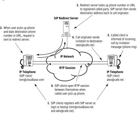
■ Under redirect operation (Figure 8), the signaling request is sent to a SIP server, which then looks up the destination address. The SIP server returns the destination address to the originator of the call, who then signals the SIP client.
Figure 8: SIP Redirector Server
One of the greatest challenges to implementing SIP services is mapping CoS delivery for the signaling and bearer traffic. With its mobile features, SIP implementations tend to be more discrete; SIP clients tend to be larger in number and more geographically distributed. You can identify SIP users, and hence CoS mappings, by having the clients set ToS bits in the IP header.
Signaling Transport
Signaling Transport (SigTran) is a working draft within the IETF (informational RFC 2719) that addresses the problem of signaling performance and signaling transport (SS7-to-VoIP). SigTran was defined to be the control protocol between the signaling gateway (for terminating the signaling associated with a given PSTN channel/circuit) and media gateway controllers. SigTran functionality also can also relay SS7 signaling messages through an IP network to PSTN termination on both ends.
SigTran usually manifests itself as a signaling gateway controller. These devices directly bridge the SS7 network to the VoIP network. SigTran is important to ensuring interoperability so as to
IP Telephone (SIP client) [email protected]
IP Telephone (SIP client) [email protected] SIP Redirect Server
IP Network
RTP Session
1. SIP clients registers with SIP server at login or bootup ([email protected] and [email protected]).
2. When user picks up phone and dials destination phone number or URL, request is sent to redirect server.
3. Redirect server looks up phone number or URL to registered called party. SIP server then sends destination address back to call originator. .
4. Call originator sends invitation to destination ([email protected]).
5. Called client is informed of incoming call by invitation message (phone ring).
6. SIP clients open RTP session between themselves when called user pick up phone.
SigTran messages need the greatest of priority for the VoIP networks to function correctly. The signaling and media gateway controllers are generally non-changing entities; once configured, they do not change locations or addresses. Since the sources and destinations of SigTran messages are rather static, classifying the signaling to CoS mechanisms is relatively straightforward.
Megaco/H.248
Megaco/H.248 is a current draft standard and represents a cooperative proposal from the IETF and ITU standards bodies. Megaco has many similarities to MGCP and borrows the same naming conventions for the VoIP elements. The Megaco architecture defines media gateways that provide media conversion and sources of calls, while media gateway controllers provide call control.
Megaco addresses the same requirements as that of MGCP and as a result, there is some effort to merge the protocols. It defines a series of transactions coordinated by a media gateway controller for the establishment of call sessions.
The primary focus of Megaco is the promotion to standardize IP telephony equipment. Some of the design goals are as follows.
■ Megaco IP phone meets the basic needs of the business user from day one.
■ Provides a path for rapid expansion to support sophisticated business telephony features.
■ Allows for a wide range of telephones and similar devices to be defined from very simple
to very feature rich.
■ Implements a simple, minimal design.
■ Allows device cost to be appropriate to capabilities provided.
■ Package and termination types have characteristics that enable reliability.
■ IP phone meets the appropriate Megaco/H.248 protocol requirements as provided in the
Megaco requirements document and are a straightforward application of the Megaco/H.248 protocol.
Resource Reservation Protocol
RSVP (RFC 2205 covers version one) is not specifically a VoIP protocol; rather, it started as a mechanism to enable QoS delivery over router-based networks for multimedia applications. RSVP was originally created to support reservation of resources (bandwidth or links) for specific applications. Each application signaled the network elements of its intention of using network resources by sending an RSVP request. This request enabled the resource to be used along the path of the traffic flow. The routers would in turn identify the specific application by its address, protocol type and port numbers. A packet scheduler or some other
link-layer-dependent mechanism would be used to determine when particular packets were forwarded. So that guarantees can be met, RSVP reservations are half duplex, needing two requests going in both directions for full-duplex operations. In the support for thousands of phone calls, RSVP being used in this capacity is not a scalable solution for large-scale VoIP
RSVP was extended for use as a signaling protocol for the setup of label switched paths (LSPs) in MPLS domains. Here, RSVP does not reserve bandwidth or a resource on a flow-by-flow basis, but rather enables the use of MPLS. In this capacity, RSVP signaled LSPs aggregates large traffic flows for VoIP services. This use of RSVP to set up LSPs does not have the same scalability issue as its use in application-level signaling because of the signaling of the LSP is a one-time event and does not affect packet scheduling.
VoIP Service Considerations
VoIP traffic has a number of issues that you must carefully consider, such as traffic parameters and network design. Without such due diligence, you could be faced with service that does not function reliably or is severely degraded. These important considerations are as follows.
■ Latency
■ Jitter
■ Bandwidth
■ Packet loss
■ Reliability
■ Security
Latency
Latency (or delay) is the time that it takes a packet to make its way through a network end to end. In telephony terms, latency is the measure of time it takes the talker's voice to reach the listener's ear. Large latency values do not necessarily degrade the sound quality of a phone call, but the result can be a lack of synchronization between the speakers such that there are hesitations in the speaker' interactions.
Generally, it is accepted that the end-to-end latency should be less than 150 ms for toll quality phone calls. To ensure that the latency budget remains below 150 ms, you need to take into account the following primary causes of latency. When designing a multiservice network, the total delay that a signal or packet exhibits is a summation of all the latency contributors.
■ One source of latency is the time it takes for the endpoints to create the packets used in voice services. These packetization delays are caused by the amount of time it takes to fill a packet with data. Generally, the larger the packet size, the greater the amount of time it takes to fill it. Packetization delay is governed by the CODEC standard being used. This problem also exists on the receiving side because the media gateway must remove and further process the packet data. If the packets are kept small, this amount of delay in both directions, is usually quite small depending on the hardware / software implementation of the media gateways. All considerations being equal, nominal operation of any media gateway unit should not exceed 30 ms.
■ Another source of latency is the delay it takes to serialize the digital data onto the physical links of the interconnecting equipment. This delay is inversely proportional to the link speed. In other words, the faster the media, the lower the latency. This value is somewhat dependent on the link technology used and its access method. For example, it takes 125 microseconds to place one byte on a 64-Kb circuit. The same byte placed on an
OC-3/STM-1 circuit takes 0.05 microseconds. Although this delay is unavoidable (regardless of the bandwidth used), keeping the number of intervening links small and using high bandwidth interfaces reduces the overall latency.
■ Propagation delay is the time it takes an electrical (or photonic) signal to traverse the length of a conductor. The speed of these signals is always slower than that of the speed of light. There is always propagation delay; however, it only becomes an issue when the signal (or packet) travels a great distance. The accepted formula for calculating propagation delay is as follows.
Propagation delay = Circuit km / (299,300 km x .6)
■ A queuing delay, which is a large source of latency, is the amount of time that a packet remains buffered in a network element while it awaits transmission. Network traffic loads result in variable queuing delays. The amount of buffer that a queue uses is usually a configurable parameter, with a smaller number being better for latency values. However, this delay is also based on the amount of traffic the element is trying to pass through a given link, and therefore it increases with network load. Hence, you need to set aside adequate bandwidth and resources for voice traffic. If the queue used for voice traffic is not serviced fast enough and that queue is allowed to grow too large, the result is greater latency.
■ Packet switching delay, yet another source of end-to-end latency, is the time it takes a router or switch to buffer a packet and make the decision on which interface the packet is to be directed. Although this delay is usually small, the architecture of the router or switch is the deciding factor. If a packet must be further buffered as a part of its processing, greater latency is incurred.
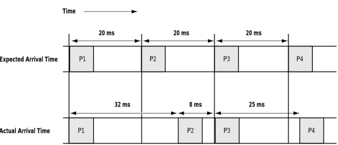
Jitter
Jitter is the measure of time between when a packet is expected to arrive to when it actually arrives. In other words, with a constant packet transmission rate of every 20 ms, every packet would be expected to arrive at the destination exactly every 20 ms. This situation is not always the case. For example, Figure 9 shows packet one (P1) and packet three (P3) arriving when expected, but packet two (P2) arriving 12 ms later than expected and packet four (P4) arriving 5 ms late.
Example: Calculation of one-way propagation delay of a 6,000 km fiber run (discounting any signal repeaters in between)
0.0334 sec = 6000 km / (299,300 km x .6)
By this calculation, the latency contributed by just propagation delay would be 33.4 ms.
Figure 9: Example Jitter
The greatest culprit of jitter is queuing variations caused by dynamic changes in network traffic loads. Another cause is packets that might sometimes take a different equal-cost link that is not physically (or electrically) the same length as the other links.
Media gateways have play-out buffers that buffer a packet stream so that the reconstructed voice waveform is not affected by packet jitter. Play-out buffers can minimize the effects of jitter, but cannot eliminate severe jitter.
Although some amount of jitter is to be expected, severe jitter can cause voice quality issues because the media gateway might discard packets arriving out of order. In this condition, the media gateway could starve its play-out buffer and cause gaps in the reconstructed waveform.
Bandwidth
You can determine how much bandwidth to set aside for voice traffic using simple math. However, in a converged voice and data network, you have to make decisions on how much bandwidth to give each service. These decisions are based on careful consideration of your priorities and the available bandwidth you can afford. If you allocate too little bandwidth for voice service, there might be unacceptable quality issues. Another consideration is that voice services are less tolerant to bandwidth depletion than that of Internet traffic. Therefore, bandwidth for voice services and associated signaling must take a priority over that of best-effort Internet traffic.
If a network were to use the same prevailing encoding (CODEC) scheme as the current PSTN system, bandwidth requirements for VoIP networks would tend to be larger than that of a circuit-switched voice network of similar capacity. The reason is the overhead in the protocols used to deliver the voice service. Typically, you would need speeds of OC-12c/STM-4 and higher to support thousands of call sessions. However, VoIP networks that employ compression and silence suppression could actually use less bandwidth than a similar circuit-switched network. The reason is because of the greater granularity in bandwidth usage that a packet-based network has in comparison to a fixed, channel size TDM network.
P2 P3 P4
P1
P2 P3 P4
P1 Time
20 ms
32 ms Expected Arrival Time
Actual Arrival Time
8 ms 25 ms
Allocations of network bandwidth are based on projected numbers of calls at peak hours. Any over-subscription of voice bandwidth can cause a reduction in voice quality. Also, you must set aside adequate bandwidth for signaling to ensure that calls are complete and to reduce service interruptions.
The formula for calculating total bandwidth needed for voice traffic is relatively
straightforward. The formula to calculate RTP bearer voice bandwidth usage for a given number of phone calls is as follows.
bits per sec = packet creation rates per sec x packet size x number of calls x 8 bits per sec where samples per sec = 1,000 ms / packet creation rate
Note that this number is a raw measure of IP traffic and does not take in account the overhead used by the transporting media (links between the routers) and data-link layer protocols. Add this raw IP value to that of the overhead to determine the link speeds needed to support this number of calls. Note this value represents only the bearer (voice) content.
Signaling bandwidth requirements vary depending on the rate at which the calls are generated and signaling protocol used. If a large number of calls are initiated in a relatively short period, the peak bandwidth needs for the signaling could be quite high. A general guideline for the maximum bandwidth requirement that an IP signaling protocol needs is roughly three percent of all bearer traffic. Using the previous example, signaling bandwidth requirements if all 2,000 calls were initiated in one second would be approximately 4.8 Mbps (3 percent of
160-megabits).
With the calculation of bearer and signaling, the total bandwidth needed to support two thousand G.711 encoded calls would be an approximate maximum of 164.8 MB. This bandwidth requirement is a theoretical maximum for this specific case. If the parameters change, such as call initiation rate, voice encoding method, packet creation rate, employment of compression, and silence suppression, the bandwidth requirements would change as well. With large VoIP implementations requiring sizable bandwidth, it becomes imperative that the IP network delivers the needed service at predictably high performance.
Packet Loss
Packet loss occurs for many reasons, and in some cases, is unavoidable. Often the amount of traffic a network is going to transport is underestimated. During network congestion, routers and switches can over flow their queue buffers and be forced to discard packets. Packet loss for non-real-time applications, such as Web browsers and file transfers, are undesirable, but not critical. The protocols used by non-real-time applications, usually TCP, are tolerant to some
Example: 2,000 full-duplex G.711 encoded voice channels that have a packet creation rate of 20 ms, with a packet size of 200 bytes (40 byte IP header + 160 byte payload)
50 samples per second = 1,000 ms / 20 ms 160 Mbps = 50 x 200 x 2,000 x 8
Real-time applications based on the UDP are significantly less tolerant to packet loss. UDP does not have retransmission facilities, however, retransmissions would almost never help. In an RTP session, by the time a media gateway could receive a retransmission, it would no longer be relative to the reconstructed voice waveform; that part of the waveform in the retransmitted packet would arrive too late.
It is important that bearer and signaling packets are not discarded, otherwise, voice quality or service disruptions might occur. In such instances, CoS mechanisms become very important. By configuring CoS parameters, you can give packets of greater importance a higher priority in the network, thus ensuring packet delivery for critical applications, even during times of network congestion.
Although packet loss of any kind is undesirable, some loss can be tolerated. Some amount of packet loss for voice services could be acceptable as long as the loss is spread out over a large amount of users. As long as the amount of packet loss is less than five percent for the total number of calls, the quality generally is not adversely affected. It is best to drop a packet, versus increasing the latency of all delivered packets by further buffering them.
Reliability
Although network failures are rare, planning for them is essential. Failover strategies are desirable for cases when network devices malfunction or links are broken. An important strategy is to deploy redundant links between network devices and/or to deploy redundant equipment. To ensure continued service, plan carefully for how media gateways and media gateway controllers can make use of the redundant schemes.
IP networks use routing protocols to exchange routing information. As part of their operation, routing protocols monitor the status of interconnecting links. Routing protocols typically detect and reroute packets around a failure if an alternate path exists. Depending on the interconnecting media used for these links, the time taken to detect and recalculate an alternate path can vary. For example, the loss of signal for a SONET/SDH connection can be detected and subsequently rerouted very quickly. However, a connection through an intervening LAN switch might need to time out the keep-alive protocol before a failure is detected.
Having media gateways and media gateway controllers that can actively detect the status of their next-hop address (default gateway) as part of their failover mechanism decreases the likelihood of a large service disruption. Another possible option is that the media gateway and media gateway controller could be directly connected to the router. In this case, the possibility of a link failure (depending on the nature of the failure) could be immediately detected and the network devices would take appropriate action. Still another option for reducing long-term failure could be to employ a redundancy mechanism such as the Virtual Router Redundancy Protocol (VRRP).
Security
Security, especially in a converged voice and data network, is a high priority. You need to protect the voice communications devices from unauthorized access and malicious attack. While you can thwart unauthorized access by using security protocols (such as RADIUS and ssh), denial-of-service (DoS) attacks can be a real danger to voice services. It is conceivable that such attacks would either cripple or completely disable voice services.
would actually only work for most of the Internet and not directly connected autonomous systems because of the possibility of default routing.) You can use private addressing only if the in-band VoIP service never crosses autonomous-system (AS) boundaries. Interface outside the network would be through the ties to the PSTN.
If any part of the VoIP service needs access to the Internet, you can configure packet filtering to provide protection. Through packet filtering, you can selectively allow the VoIP devices to communicate with each other while denying traffic from possible attackers. It is important that whatever packet filtering is employed does not impact the network performance. Any gains made in protecting the equipment from attack could be lost with routers / switches that cannot perform filtering without compromising performance. Security of the actual IP network is also an important consideration. A malicious attack on an IP network, specifically the routers that carry the traffic, could compromise the network services. Someone using a router or similarly capable device connected to the network could spoof the routing protocols and cause
disruption.
Juniper Networks VoIP Network Solutions
Juniper Networks routers are ideal for providing IP backbones for converged packet and voice networks. VoIP networks have a number of needs that play to the strength of Juniper
Networks routers, as follows.
■ High-speed interfaces
■ Predictable performance
■ Class of service
■ Low latency
■ Predictable and minimal jitter
■ Per-flow load balancing
■ MPLS
■ Security
■ Reliability mechanisms
High-speed Interfaces
Our routers are designed for carrier-grade, multiservice networks. With the bandwidth needs of large-scale VoIP networks that can support thousands of calls, having an IP network that scales to any speed is paramount. Our routers support the industry's highest interface speeds available. We offer standards-based interfaces ranging from DS-1 up to OC-192c/STM-64 speeds. Regardless of the size of the VoIP network, we have a router that can match the needed interface bandwidth, port density, scalability, and space considerations.
Predictable Performance
Interface speeds are meaningless if the router cannot forward packets at those speeds. Our routers use industry-leading ASIC technology to enable uncompromising performance on all router interfaces. These ASIC-powered routers are substantially faster than general-purpose, microprocessor-based routers in their ability to both process and forward IP packets because
Our feature-rich ASICs deliver a comprehensive hardware-based system for route lookups, filtering, sampling, load balancing, buffer management, switching, encapsulation, and de-encapsulation functions. Not only do we predictably deliver all packets, but we also ensure packet-processing tasks, such as CoS, filtering, and sampling, do not significantly impede performance. To ensure a non-blocking forwarding path, all channels between the ASICs are oversized, dedicated paths.
Class of Service
CoS mechanisms (Figure 10) schedule packets of greater importance to be expedited quicker by the router or switch. Hence, a greater percentage of the available bandwidth is allocated for the specified service.
For interfaces that carry IPv4 or MPLS traffic, you can configure Juniper Networks CoS features to provide multiple service levels for different applications. You can configure multiple output queues for transmitting packets, define which packets are placed into each output queue, schedule the transmission service level for each queue using a weighted round-robin (WRR) algorithm, and manage congestion using a random early detection (RED) algorithm.
Figure 10: Juniper Networks Class of Service
Input Traffic
Over Threshold?
Drop or Tag Packet?
Output Queue 0 Output Queue 1 Output Queue 2 Output Queue 3 Output Queue 3 CoS Mapping
(TOS, DiffServ, Interface, Source, Destination IP, and more)
Precedence Bits Rewrite WRR
RED
Transmit Packet
Drop Packet
Step 1 Step 2 Steps 3 and 4 Step 5
Drop Packet
Tag Packet Input
Traffic
Yes
These steps represent the numbers in Figure 10.
Step 1 You can rate limit (police) traffic into a given interface by using a configurable leaky or token bucket algorithm. If the flow exceeds the bucket's threshold, the router drops or tags the packets, depending on how you configured the receive leaky bucket mechanism. If you configured it to tag packets, the PIC sets the packet loss priority (PLP) bit in the
notification record associated with the packet to indicate that the packet encountered congestion in the router or exceeded the bandwidth threshold. It also indicates that the packet has a greater probability of being dropped from the output transmission queue.
In Juniper Networks routers, the Internet Processor II ASIC performs the policing function, not the PIC.
Step 2 Identify the applications that need CoS delivery and map that traffic flow to a specific output queue. Before being placed on a transmission queue, the router classifies packets based on the value of the precedence bits in the IP ToS field.
An alternative is that you can map an input interface to a priority level. In addition, to the precedence bits in the ToS field, you can map Diffserv bit patterns to a specific transmission queue.
Another option is to reclassify packets after going through the input-stage classification. This reclassification process is undertaken by a filter operation that overwrites the initial classification result. Since you can configure a filter to match any key item, such as source address, destination address, or application port, you can define a traffic flow to forward to a desired output queue using a filter.
The priority level represents the service level to apply to the packet and corresponds to an output transmission queue. Each link can have up to four output transmission queues.
The router also checks the least-significant bit of the precedence bits in the IPv4 ToS field to determine the status of the packet's PLP bit. (In big endian terminology, it is bit 2 of the ToS. In little endian terminology, it is bit 5.) For IPv4 traffic, if this bit is set, the PIC sets the packet's PLP bit. For MPLS traffic, if this bit is set, the low-order bit in the MPLS header's CoS field is set to 1.
CoS Application
The strategy for planning and configuring CoS is based on the amount of bandwidth that is needed by the voice service. Carefully consider the selection of output, weight, and size of the queues.
The default configuration (Figure 11) for Juniper Networks CoS is that all the traffic (aside from the routing protocols) is put into queue 0, while the routing protocols are put into queue 3.
Steps 3 and 4 A WRR scheme determines the queue from which the next packet is transmitted. The weighting is based on the amount of bandwidth allocated for each queue. The percentage of weight allocated to each output
transmission queue determines how often WRR services the queue, with higher percentages resulting in more frequent service. For example, an output queue to which you allocate 50 percent of the weight is serviced twice as often as one to which you allocate 25 percent. Also, part of the queue servicing is the ability to specify the depth of the output queues. For real-time traffic such as voice, it is advantageous to select a buffer depth that is relatively small in comparison to best-effort Internet traffic. This process keeps latency at a minimum.
RED tries to anticipate incipient congestion and reacts by dropping a small percentage of packets from the head of the queue to ensure it never actually becomes congested. RED examines the fullness of each output transmission queue to determine whether it is congested.
In general, RED adds no value to the delivery of real-time (UDP) voice traffic because RED helps regulate TCP (such as browser and ftp) traffic by triggering the protocol to slow down the endpoints' transmission. RED can drop acknowledgments, which signals the endpoints to slow down their transmission, reducing the probability of congestion. However, RED is a requirement to enable that the packets are to be dropped from the head of the output queue instead of the tail.
Step 5 (Optional) Rewrite the precedence bits. This rewrite can occur if the application does not have the facility to set the precedence bits or if you do not trust the application. If the media gateway or gateway controller cannot set ToS bits, precedence rewrites are required to have a consistent CoS mapping throughout the entire IP backbone. For each output transmission queue, rewrite the IP precedence bits in the IP headers of all packets headed for that queue based on whether the PLP bit is set for the packet. You can set one precedence bit value for all packets whose PLP bit is set and a second value for those whose PLP bit is not set.
Figure 11: Juniper Networks Class-of-service Default
Queue 0's WRR is serviced 95 percent, while the routing protocol (queue 3) is serviced 5 percent. The default queue size for Internet traffic is set to 95 percent, and the routing protocol is 5 percent of the available queue space. This CoS configuration is well suited for Internet traffic. However, ideally you would change this default configuration to accommodate your specific network and business requirements.
Example CoS Configuration
Figure 12 shows an example network with a simple multiservice network topology requiring both voice and data.
Figure 12: Example Multiservice Network Output Queue 0
(Internet Traffic) Output Queue 3 (Routing Protocols)
Output Queue 0 (Internet Traffic) Output Queue 3 (Routing Protocols) Queue WRR
Queue Size
95 %
95 % 5 %
5 %
M40 M160
Media Gateway Controller
Internet Internet
PSTN
Site 1 Site 2
OC -12c/STM-4
PSTN
In this example, the provider wishes to use only one additional output queue for the voice service, which can be accomplished by classifying both the bearer and signaling traffic into this single queue. (An option to this would be to use one output queue for the bearer traffic and another queue for the signaling traffic.)
Table 2 shows the single queue configuration for this scenario. 1. Calculate the bearer voice bandwidth requirements.
The following table lists the RTP bearer voice bandwidth calculations, which result in the raw IP bandwidth for the bearer channels.
2. Calculate the signaling requirements.
Using the general guideline that 3 percent of bearer traffic should be set aside for signaling, the bandwidth requirement for all these calls initiated in 1 second is 9.6 Mbps (3 percent of 320 Mb). For a call initiation rate of 1,000 calls a second, the signaling bandwidth needed is 2.4 Mbps (25 percent of 9.6 Mbps). The total amount of bandwidth needed for bearer and signaling is as follows.
Voice bandwidth requirement = bearer voice + signaling bandwidth 322.4 Mbps = 320 Mbps + 2.4 Mbps
3. Calculate the total bandwidth as percentage of link speed.
The above calculations are a measure of pure IP traffic. SONET/SDH has an overhead associated with it. OC-12c/STM-4 interfaces have a speed of 622.080 Mbps, of which the usable payload is 601.344 Mbps. There is also a link layer protocol overhead such as HDLC or PPP that you need to take into account. The percentage of bandwidth (out of the OC-12c/STM-4 link) required for the bearer voice channels and signaling is as follows. Percentage of bandwidth = voice bandwidth requirement / (usable payload / 100) 53.61 percent = 322.4 Mbps / (601.344 Mbps / 100)
Rounding up this percentage to the nearest five percent should cover the Layer-two overhead, which is usually two bytes for each packet.
Table 2: Example Queue Configuration
Variable Amount Calculation
G.711 encoded voice channels
4,000 N/A
Packet creation rate 20 ms N/A
Packet sample / second 50 Packet creation rate = 1 second / 20 ms
Packet size 200 bytes Packet size = IP header + RTP payload = 40 + 160
Queue bandwidth requirement
320 Mbps Bits per second = sample per second x packet size x number of call sessions x bits per second
Remember, it is always a good idea to over-provision more bandwidth than what is needed. You could further increase this figure as a percentage of available bandwidth to provide a measure of service insurance. This example shows how to configure an exact CoS configuration with no margin of error.
4. Map services to output queues.
The servicing for the output queues used by the voice service in this example would be 55 percent for the WRR mechanism. The size of the voice service queue should be small compared to other services queues to help with latency issues. For example, if the
maximum delay due to queuing were 170 ms, a queue size of 10 percent would equate to 17 ms (10 percent of 170) of maximum latency for this single router hop. (The queue latency would be zero if there were no other packets waiting.)
Figure 13 shows how you could configure this mapping of services to output queues. Figure 13: Example Mapping of Services to Output Queues
Once you calculated the setup of the output queues for the voice services, you can configure the other queues. These parameters would be applied to the CoS configuration of the OC-12c/STM-4 interfaces on routers R1 and R2 (Figure 12).
Using similar calculations, configure the other links connecting the routers to the voice gateway and the media gateway controller. The link speeds and data-link overhead arrives at the output queue configurations for those links.
Output Queue 0 (Internet Traffic) Output Queue 1 (Voice Bearer/ Signaling Traffic)
Output Queue 3 (Routing Protocols)
Output Queue 0 (Internet Traffic) Output Queue 1 (Voice Bearer/ Signaling Traffic)
Output Queue 3 (Routing Protocols) Queue WRR
40 %
5 %
55 %
85 %
5 % 10 % Queue Size