Linux Virtual Server Administration
RHEL5: Linux Virtual Server (LVS)
Linux Virtual Server Administration: RHEL5: Linux Virtual
Server (LVS)
Copyright©2007 Red Hat, Inc.
Building a Linux Virtual Server (LVS) system offers highly-available and scalable solution for production services using specialized routing and load-balancing techniques configured through the PIRANHA. This book discusses the configuration of high-performance systems and services with Red Hat Enterprise Linux and LVS.
1801 Varsity Drive Raleigh, NC 27606-2072 USA
Phone: +1 919 754 3700 Phone: 888 733 4281 Fax: +1 919 754 3701 PO Box 13588
Research Triangle Park, NC 27709 USA
Documentation-Deployment
Copyright©2007 by Red Hat, Inc. This material may be distributed only subject to the terms and conditions set forth in the Open Publication License, V1.0 or later (the latest version is presently available at
ht-tp://www.opencontent.org/openpub/).
Distribution of substantively modified versions of this document is prohibited without the explicit permission of the copy-right holder.
Distribution of the work or derivative of the work in any standard (paper) book form for commercial purposes is prohib-ited unless prior permission is obtained from the copyright holder.
Red Hat and the Red Hat "Shadow Man" logo are registered trademarks of Red Hat, Inc. in the United States and other countries.
All other trademarks referenced herein are the property of their respective owners. The GPG fingerprint of the [email protected] key is:
Table of Contents
1. Introduction to Linux Virtual Server ... 1
1. Technology Overview ... 1
2. Basic Configurations ... 2
2.1. Load-Balancing Clusters Using Linux Virtual Servers ... 2
2. Linux Virtual Server Overview ... 3
1. A Basic LVS Configuration ... 3
1.1. Data Replication and Data Sharing Between Real Servers ... 5
2. A Three Tiered LVS Configuration ... 5
3. LVS Scheduling Overview ... 7
3.1. Scheduling Algorithms ... 7
3.2. Server Weight and Scheduling ... 8
4. Routing Methods ... 9
4.1. NAT Routing ... 9
4.2. Direct Routing ...11
5. Persistence and Firewall Marks ...12
5.1. Persistence ...12
5.2. Firewall Marks ...13
6. LVS Cluster — A Block Diagram ...13
6.1. Components of an LVS Cluster ...14
3. Initial LVS Configuration ...16
1. Configuring Services on the LVS Routers ...16
2. Setting a Password for the Piranha Configuration Tool ...17
3. Starting the Piranha Configuration Tool Service ...17
3.1. Configuring the Piranha Configuration Tool Web Server Port ...18
4. Limiting Access To the Piranha Configuration Tool ...19
5. Turning on Packet Forwarding ...19
6. Configuring Services on the Real Servers ...20
4. Setting Up a Red Hat Enterprise Linux LVS Cluster ...21
1. The NAT LVS Cluster ...21
1.1. Configuring Network Interfaces for a NAT LVS Cluster ...21
1.2. Routing on the Real Servers ...23
1.3. Enabling NAT Routing on the LVS Routers ...23
2. LVS Cluster via Direct Routing ...24
2.1. Direct Routing and arptables_jf ...25
2.2. Direct Routing and IPTables ...26
3. Putting the Cluster Together ...27
3.1. General LVS Networking Tips ...27
4. Multi-port Services and LVS Clustering ...28
4.1. Assigning Firewall Marks ...28
5. FTP In an LVS Cluster ...29
5.1. How FTP Works ...29
5.2. How This Affects LVS Routing ...30
1. Necessary Software ...33
2. Logging Into the Piranha Configuration Tool ...33
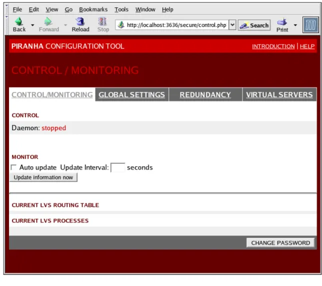
3. CONTROL/MONITORING ...34
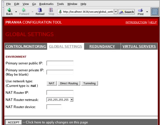
4. GLOBAL SETTINGS ...36
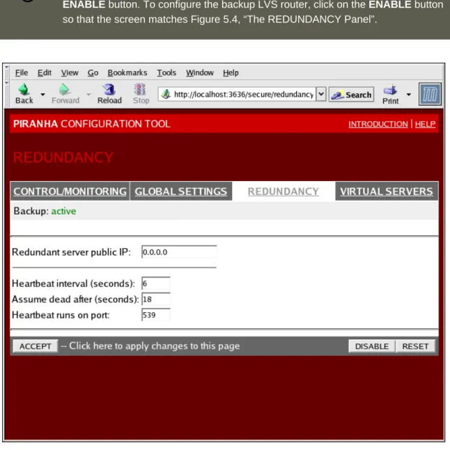
5. REDUNDANCY ...38
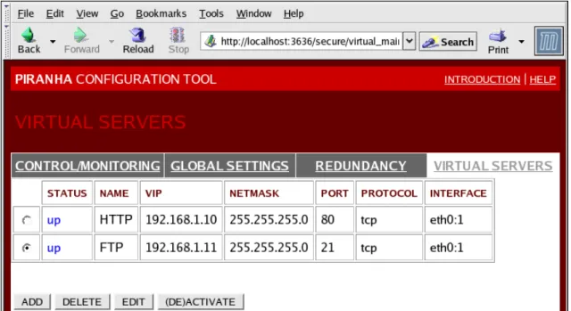
6. VIRTUAL SERVERS ...39
6.1. The VIRTUAL SERVER Subsection ...40
6.2. REAL SERVER Subsection ...44
6.3. EDIT MONITORING SCRIPTS Subsection ...46
7. Synchronizing Configuration Files ...48
7.1. Synchronizing lvs.cf ...48
7.2. Synchronizing sysctl ...49
7.3. Synchronizing Network Packet Filtering Rules ...49
8. Starting the Cluster ...50
A. Using LVS with Red Hat Cluster ...51
Index ...53 Linux Virtual Server Administration
Chapter 1. Introduction to Linux
Virtual Server
Using Red Hat Enterprise Linux, it is possible to create highly available server clustering solu-tions able to withstand many common hardware and software failures with little or no interrup-tion of critical services. By allowing multiple computers to work together in offering these critical services, system administrators can plan and execute system maintenance and upgrades without service interruption.
The chapters in this part guide you through the following steps in understanding and deploying a clustering solution based on the Red Hat Enterprise Linux Linux Virtual Server (LVS) techno-logy:
• Explains the Linux Virtual Server technology used by Red Hat Enterprise Linux to create a load-balancing cluster
• Explains how to configure a Red Hat Enterprise Linux LVS cluster
• Guides you through the Piranha Configuration Tool, a graphical interface used for config-uring and monitoring an LVS cluster
1. Technology Overview
Red Hat Enterprise Linux implements highly available server solutions via clustering. It is im-portant to note that cluster computing consists of three distinct branches:
• Compute clustering (such as Beowulf) uses multiple machines to provide greater computing power for computationally intensive tasks. This type of clustering is not addressed by Red Hat Enterprise Linux.
• High-availability (HA) clustering uses multiple machines to add an extra level of reliability for a service or group of services.
• Load-balance clustering uses specialized routing techniques to dispatch traffic to a pool of servers.
Red Hat Enterprise Linux addresses the latter two types of clustering technology. Using a col-lection of programs to monitor the health of the systems and services in the cluster.
Note
The clustering technology included in Red Hat Enterprise Linux is not synonymous with fault tolerance. Fault tolerant systems use highly specialized and often very expensive hardware to implement a fully redundant environment in which services
However, fault tolerant systems do not account for operator and software errors which Red Hat Enterprise Linux can address through service redundancy. Also, since Red Hat Enterprise Linux is designed to run on commodity hardware, it cre-ates an environment with a high level of system availability at a fraction of the cost of fault tolerant hardware.
2. Basic Configurations
While Red Hat Enterprise Linux can be configured in a variety of different ways, the configura-tions can be broken into two major categories:
• High-availability clusters using Red Hat Cluster Manager • Load-balancing clusters using Linux Virtual Servers
This part explains what a load-balancing cluster system is and how to configure a load-bal-ancing system using Linux Virtual Servers on Red Hat Enterprise Linux.
2.1. Load-Balancing Clusters Using Linux Virtual Servers
To an outside user accessing a hosted service (such as a website or database application), a Linux Virtual Server (LVS) cluster appears as one server. In reality, however, the user is actually accessing a cluster of two or more servers behind a pair of redundant LVS routers that distribute client requests evenly throughout the cluster system. Load-balanced clustered services allow administrators to use commodity hardware and Red Hat Enterprise Linux to create continuous and consistent access to all hosted services while also addressing availability requirements. An LVS cluster consists of at least two layers. The first layer is composed of a pair of similarly configured Linux machines or cluster members. One of these machine acts as the LVS routers, configured to direct requests from the Internet to the cluster. The second layer consists of a cluster of machines called real servers. The real servers provide the critical services to the end-user while the LVS router balances the load on these servers.
For a detailed overview of LVS clustering, refer to Chapter 2, Linux Virtual Server Overview. 2. Basic Configurations
Chapter 2. Linux Virtual Server
Overview
Red Hat Enterprise Linux LVS clustering uses a Linux machine called the active router to send requests from the Internet to a pool of servers. To accomplish this, LVS clusters consist of two basic machine classifications — the LVS routers (one active and one backup) and a pool of real servers which provide the critical services.
The active router serves two roles in the cluster:
• To balance the load on the real servers.
• To check the integrity of the services on each of the real servers.
The backup router's job is to monitor the active router and assume its role in the event of failure.
1. A Basic LVS Configuration
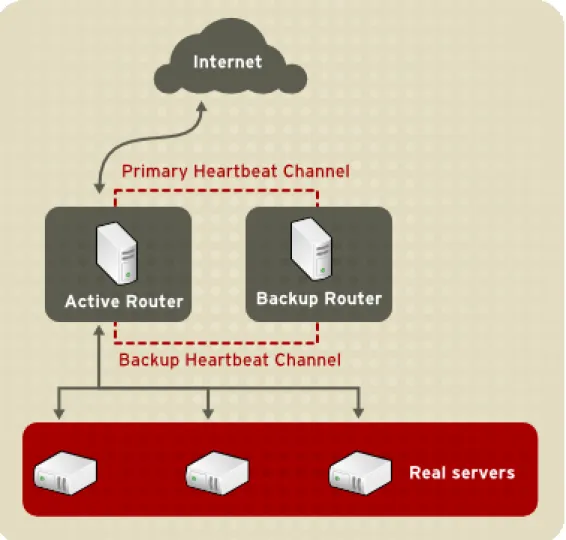
Figure 2.1, “A Basic LVS Configuration” shows a simple LVS cluster consisting of two layers. On the first layer are two LVS routers — one active and one backup. Each of the LVS routers has two network interfaces, one interface on the Internet and one on the private network, enabling them to regulate traffic between the two networks. For this example the active router is using Network Address Translation or NAT to direct traffic from the Internet to a variable number of real servers on the second layer, which in turn provide the necessary services. Therefore, the real servers in this example are connected to a dedicated private network segment and pass all public traffic back and forth through the active LVS router. To the outside world, the server cluster appears as one entity.
1A virtual server is a service configured to listen on a specific virtual IP. Refer to Section 6, “VIRTUAL SERVERS” for
more on configuring a virtual server using the Piranha Configuration Tool.
Figure 2.1. A Basic LVS Configuration
Service requests arriving at the LVS cluster are addressed to a virtual IP address or VIP. This is a publicly-routable address the administrator of the site associates with a fully-qualified domain name, such as www.example.com, and which is assigned to one or more virtual server1. Note that a VIP address migrates from one LVS router to the other during a failover, thus maintaining a presence at that IP address, also known as floating IP addresses.
VIP addresses may be aliased to the same device which connects the LVS router to the Inter-net. For instance, if eth0 is connected to the Internet, than multiple virtual servers can be aliased toeth0:1. Alternatively, each virtual server can be associated with a separate device per
service. For example, HTTP traffic can be handled oneth0:1, and FTP traffic can be handled on eth0:2.
Only one LVS router is active at a time. The role of the active router is to redirect service re-quests from virtual IP addresses to the real servers. The redirection is based on one of eight supported load-balancing algorithms described further in Section 3, “LVS Scheduling Overview”. The active router also dynamically monitors the overall health of the specific services on the real servers through simple send/expect scripts. To aid in detecting the health of services that
quire dynamic data, such as HTTPS or SSL, the administrator can also call external execut-ables. If a service on a real server malfunctions, the active router stops sending jobs to that server until it returns to normal operation.
The backup router performs the role of a standby system. Periodically, the LVS routers ex-change heartbeat messages through the primary external public interface and, in a failover situ-ation, the private interface. Should the backup node fail to receive a heartbeat message within an expected interval, it initiates a failover and assumes the role of the active router. During fail-over, the backup router takes over the VIP addresses serviced by the failed router using a tech-nique known as ARP spoofing — where the backup LVS router announces itself as the destina-tion for IP packets addressed to the failed node. When the failed node returns to active service, the backup node assumes its hot-backup role again.
The simple, two-layered configuration used in Figure 2.1, “A Basic LVS Configuration” is best for clusters serving data which does not change very frequently — such as static webpages — be-cause the individual real servers do not automatically sync data between each node.
1.1. Data Replication and Data Sharing Between Real
Serv-ers
Since there is no built-in component in LVS clustering to share the same data between the real servers, the administrator has two basic options:
• Synchronize the data across the real server pool • Add a third layer to the topology for shared data access
The first option is preferred for servers that do not allow large numbers of users to upload or change data on the real servers. If the cluster allows large numbers of users to modify data, such as an e-commerce website, adding a third layer is preferable.
1.1.1. Configuring Real Servers to Synchronize Data
There are many ways an administrator can choose to synchronize data across the pool of real servers. For instance, shell scripts can be employed so that if a Web engineer updates a page, the page is posted to all of the servers simultaneously. Also, the cluster administrator can use programs such asrsyncto replicate changed data across all nodes at a set interval.
However, this type of data synchronization does not optimally function if the cluster is over-loaded with users constantly uploading files or issuing database transactions. For a cluster with a high load, a three-tiered topology is the ideal solution.
2. A Three Tiered LVS Configuration
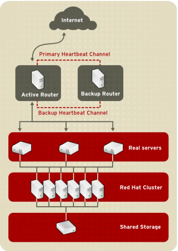
Figure 2.2, “A Three Tiered LVS Configuration” shows a typical three tiered LVS cluster topo-logy. In this example, the active LVS router routes the requests from the Internet to the pool of real servers. Each of the real servers then accesses a shared data source over the network.
Figure 2.2. A Three Tiered LVS Configuration
This configuration is ideal for busy FTP servers, where accessible data is stored on a central, highly available server and accessed by each real server via an exported NFS directory or Samba share. This topography is also recommended for websites that access a central, highly available database for transactions. Additionally, using an active-active configuration with Red Hat Cluster Manager, administrators can configure one high-availability cluster to serve both of these roles simultaneously.
The third tier in the above example does not have to use Red Hat Cluster Manager, but failing to use a highly available solution would introduce a critical single point of failure.
3. LVS Scheduling Overview
One of the advantages of using an LVS cluster is its ability to perform flexible, IP-level load bal-ancing on the real server pool. This flexibility is due to the variety of scheduling algorithms an administrator can choose from when configuring a cluster. LVS load balancing is superior to less flexible methods, such as Round-Robin DNS where the hierarchical nature of DNS and the caching by client machines can lead to load imbalances. Additionally, the low-level filtering em-ployed by the LVS router has advantages over application-level request forwarding because balancing loads at the network packet level causes minimal computational overhead and allows for greater scalability.
Using scheduling, the active router can take into account the real servers' activity and, option-ally, an administrator-assigned weight factor when routing service requests. Using assigned weights gives arbitrary priorities to individual machines. Using this form of scheduling, it is pos-sible to create a group of real servers using a variety of hardware and software combinations and the active router can evenly load each real server.
The scheduling mechanism for an LVS cluster is provided by a collection of kernel patches called IP Virtual Server or IPVS modules. These modules enable layer 4 (L4) transport layer switching, which is designed to work well with multiple servers on a single IP address.
To track and route packets to the real servers efficiently, IPVS builds an IPVS table in the ker-nel. This table is used by the active LVS router to redirect requests from a virtual server address to and returning from real servers in the pool. The IPVS table is constantly updated by a utility called ipvsadm — adding and removing cluster members depending on their availability.
3.1. Scheduling Algorithms
The structure that the IPVS table takes depends on the scheduling algorithm that the adminis-trator chooses for any given virtual server. To allow for maximum flexibility in the types of ser-vices you can cluster and how these serser-vices are scheduled, Red Hat Enterprise Linux provides the following scheduling algorithms listed below. For instructions on how to assign scheduling algorithms refer to Section 6.1, “The VIRTUAL SERVER Subsection”.
Round-Robin Scheduling
Distributes each request sequentially around the pool of real servers. Using this algorithm, all the real servers are treated as equals without regard to capacity or load. This scheduling model resembles round-robin DNS but is more granular due to the fact that it is network-connection based and not host-based. LVS round-robin scheduling also does not suffer the imbalances caused by cached DNS queries.
Weighted Round-Robin Scheduling
Distributes each request sequentially around the pool of real servers but gives more jobs to servers with greater capacity. Capacity is indicated by a user-assigned weight factor, which is then adjusted upward or downward by dynamic load information. Refer to Section 3.2,
Weighted round-robin scheduling is a preferred choice if there are significant differences in the capacity of real servers in the pool. However, if the request load varies dramatically, the more heavily weighted server may answer more than its share of requests.
Least-Connection
Distributes more requests to real servers with fewer active connections. Because it keeps track of live connections to the real servers through the IPVS table, least-connection is a type of dynamic scheduling algorithm, making it a better choice if there is a high degree of variation in the request load. It is best suited for a real server pool where each member node has roughly the same capacity. If a group of servers have different capabilities, weighted least-connection scheduling is a better choice.
Weighted Least-Connections (default)
Distributes more requests to servers with fewer active connections relative to their capacit-ies. Capacity is indicated by a user-assigned weight, which is then adjusted upward or downward by dynamic load information. The addition of weighting makes this algorithm ideal when the real server pool contains hardware of varying capacity. Refer to Section 3.2, “Server Weight and Scheduling” for more on weighting real servers.
Locality-Based Least-Connection Scheduling
Distributes more requests to servers with fewer active connections relative to their destina-tion IPs. This algorithm is designed for use in a proxy-cache server cluster. It routes the packets for an IP address to the server for that address unless that server is above its capa-city and has a server in its half load, in which case it assigns the IP address to the least loaded real server.
Locality-Based Least-Connection Scheduling with Replication Scheduling
Distributes more requests to servers with fewer active connections relative to their destina-tion IPs. This algorithm is also designed for use in a proxy-cache server cluster. It differs from Locality-Based Least-Connection Scheduling by mapping the target IP address to a subset of real server nodes. Requests are then routed to the server in this subset with the lowest number of connections. If all the nodes for the destination IP are above capacity, it replicates a new server for that destination IP address by adding the real server with the least connections from the overall pool of real servers to the subset of real servers for that destination IP. The most loaded node is then dropped from the real server subset to prevent over-replication.
Destination Hash Scheduling
Distributes requests to the pool of real servers by looking up the destination IP in a static hash table. This algorithm is designed for use in a proxy-cache server cluster.
Source Hash Scheduling
Distributes requests to the pool of real servers by looking up the source IP in a static hash table. This algorithm is designed for LVS routers with multiple firewalls.
3.2. Server Weight and Scheduling
The administrator of an LVS cluster can assign a weight to each node in the real server pool. This weight is an integer value which is factored into any weight-aware scheduling algorithms (such as weighted least-connections) and helps the LVS router more evenly load hardware with different capabilities.
Weights work as a ratio relative to one another. For instance, if one real server has a weight of 1 and the other server has a weight of 5, then the server with a weight of 5 gets 5 connections for every 1 connection the other server gets. The default value for a real server weight is 1.
Although adding weight to varying hardware configurations in a real server pool can help load-balance the cluster more efficiently, it can cause temporary imload-balances when a real server is in-troduced to the real server pool and the virtual server is scheduled using weighted least-connections. For example, suppose there are three servers in the real server pool. Servers A and B are weighted at 1 and the third, server C, is weighted at 2. If server C goes down for any reason, servers A and B evenly distributes the abandoned load. However, once server C comes back online, the LVS router sees it has zero connections and floods the server with all incoming requests until it is on par with servers A and B.
To prevent this phenomenon, administrators can make the virtual server a quiesce server — anytime a new real server node comes online, the least-connections table is reset to zero and the LVS router routes requests as if all the real servers were newly added to the cluster.
4. Routing Methods
Red Hat Enterprise Linux uses Network Address Translation or NAT routing for LVS clustering, which allows the administrator tremendous flexibility when utilizing available hardware and in-tegrating the cluster into an existing network.
4.1. NAT Routing
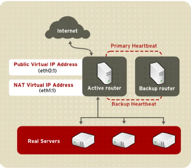
Figure 2.3, “An LVS Cluster Implemented with NAT Routing”, illustrates an LVS cluster utilizing NAT routing to move requests between the Internet and a private network.
Figure 2.3. An LVS Cluster Implemented with NAT Routing
In the example, there are two NICs in the active LVS router. The NIC for the Internet has a real IP address on eth0 and has a floating IP address aliased to eth0:1. The NIC for the private net-work interface has a real IP address on eth1 and has a floating IP address aliased to eth1:1. In the event of failover, the virtual interface facing the Internet and the private facing virtual inter-face are taken-over by the backup LVS router simultaneously. All of the cluster's real servers located on the private network use the floating IP for the NAT router as their default route to communicate with the active LVS router so that their abilities to respond to requests from the In-ternet is not impaired.
In this example, the LVS router's public LVS floating IP address and private NAT floating IP ad-dress are aliased to two physical NICs. While it is possible to associate each floating IP adad-dress to its own physical device on the LVS router nodes, having more than two NICs is not a require-ment.
Using this topography, the active LVS router receives the request and routes it to the appropri-ate server. The real server then processes the request and returns the packets to the LVS router which uses network address translation to replace the address of the real server in the packets with the LVS routers public VIP address. This process is called IP masquerading be-cause the actual IP addresses of the real servers is hidden from the requesting clients.
Using this NAT routing, the real servers may be any kind of machine running various operating systems. The main disadvantage is that the LVS router may become a bottleneck in large cluster deployments because it must process outgoing as well as incoming requests.
4.2. Direct Routing
Building an LVS setup that uses direct routing provides increased performance benefits com-pared to other LVS networking topographies. Direct routing allows the real servers to process and route packets directly to a requesting user rather than passing all outgoing packets through the LVS router. Direct routing reduces the possibility of network performance issues by relegat-ing the job of the LVS router to processrelegat-ing incomrelegat-ing packets only.
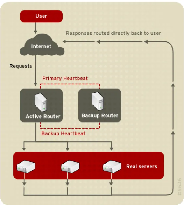
Figure 2.4. An LVS Cluster Implemented with Direct Routing
In the typical direct routing LVS setup, the LVS router receives incoming server requests through the virtual IP (VIP) and uses a scheduling algorithm to route the request to the real servers. The real server processes the request and sends the response directly to the client, by-passing the LVS routers. This method of routing allows for scalability in that real servers can be added without the added burden on the LVS router to route outgoing packets from the real serv-er to the client, which can become a bottleneck undserv-er heavy network load.
4.2.1. Direct Routing and the ARP Limitation
While there are many advantages to using direct routing in LVS, there are limitations as well. The most common issue with LVS via direct routing is with Address Resolution Protocol (ARP). In typical situations, a client on the Internet sends a request to an IP address. Network routers typically send requests to their destination by relating IP addresses to a machine's MAC ad-dress with ARP. ARP requests are broadcasted to all connected machines on a network, and the machine with the correct IP/MAC address combination receives the packet. The IP/MAC as-sociations are stored in an ARP cache, which is cleared periodically (usually every 15 minutes) and refilled with IP/MAC associations.
The issue with ARP requests in a direct routing LVS setup is that because a client request to an IP address must be associated with a MAC address for the request to be handled, the virtual IP address of the LVS system must also be associated to a MAC as well. However, since both the LVS router and the real servers all have the same VIP, the ARP request will be broadcasted to all the machines associated with the VIP. This can cause several problems, such as the VIP be-ing associated directly to one of the real servers and processbe-ing requests directly, bypassbe-ing the LVS router completely and defeating the purpose of the LVS setup. While this issue can be remedied by using an LVS router with a powerful CPU that can respond quicker to client quests, if the LVS router is under heavy load, then it may be slower to respond to the ARP re-quest than an underutilized real server, which responds quicker and is assigned the VIP in the ARP cache of the requesting client.
To solve this issue, the incoming requests should only associate the VIP to the LVS router, which will properly process the requests and send them to the real server pool. This can be done by using the either thearptables_jfor the IPTables packet filtering tool. For more
inform-ation on usingarptablesin a direct routing LVS environment, refer to Section 2.1, “Direct
Rout-ing and arptables_jf” or Section 2.2, “Direct RoutRout-ing and IPTables”.
5. Persistence and Firewall Marks
In certain situations, it may be desirable for a client to reconnect repeatedly to the same real server, rather than have an LVS load balancing algorithm send that request to the best available server. Examples of such situations include multi-screen web forms, cookies, SSL, and FTP connections. In these cases, a client may not work properly unless the transactions are being handled by the same server to retain context. LVS provides two different features to handle this: persistence and firewall marks.
5.1. Persistence
When enabled, persistence acts like a timer. When a client connects to a service, LVS remem-bers the last connection for a specified period of time. If that same client IP address connects
again within that period, it is sent to the same server it connected to previously — bypassing the load-balancing mechanisms. When a connection occurs outside the time window, it is handled according to the scheduling rules in place.
Persistence also allows the administrator to specify a subnet mask to apply to the client IP ad-dress test as a tool for controlling what adad-dresses have a higher level of persistence, thereby grouping connections to that subnet.
Grouping connections destined for different ports can be important for protocols which use more than one port to communicate, such as FTP. However, persistence is not the most efficient way to deal with the problem of grouping together connections destined for different ports. For these situations, it is best to use firewall marks.
5.2. Firewall Marks
Firewall marks are an easy and efficient way to a group ports used for a protocol or group of re-lated protocols. For instance, if an LVS cluster is deployed to run an e-commerce site, firewall marks can be used to bundle HTTP connections on port 80 and secure, HTTPS connections on port 443. By assigning the same firewall mark to the virtual server for each protocol, state in-formation for the transaction can be preserved because the LVS router forwards all requests to the same real server after a connection is opened.
Because of its efficiency and ease-of-use, administrators of LVS clusters should use firewall marks instead of persistence whenever possible for grouping connections. However, adminis-trators should still add persistence to the virtual servers in conjunction with firewall marks to en-sure the clients are reconnected to the same server for an adequate period of time.
6. LVS Cluster — A Block Diagram
LVS routers use a collection of programs to monitor cluster members and cluster services. Fig-ure 2.5, “Components of a Running LVS Cluster” illustrates how these various programs on both the active and backup LVS routers work together to manage the cluster.
Figure 2.5. Components of a Running LVS Cluster
Thepulsedaemon runs on both the active and passive LVS routers. On the backup router, pulsesends a heartbeat to the public interface of the active router to make sure the active
router is still properly functioning. On the active router,pulsestarts thelvsdaemon and
re-sponds to heartbeat queries from the backup LVS router.
Once started, thelvsdaemon calls theipvsadmutility to configure and maintain the IPVS routing
table in the kernel and starts anannyprocess for each configured virtual server on each real
server. Eachnannyprocess checks the state of one configured service on one real server, and
tells thelvsdaemon if the service on that real server is malfunctioning. If a malfunction is
detec-ted, thelvsdaemon instructsipvsadmto remove that real server from the IPVS routing table.
If the backup router does not receive a response from the active router, it initiates failover by callingsend_arpto reassign all virtual IP addresses to the NIC hardware addresses (MAC
ad-dress) of the backup node, sends a command to the active router via both the public and private network interfaces to shut down thelvsdaemon on the active router, and starts thelvsdaemon
on the backup node to accept requests for the configured virtual servers.
6.1. Components of an LVS Cluster
Section 6.1.1, “pulse” shows a detailed list of each software component in an LVS router. 6.1. Components of an LVS Cluster
6.1.1.
pulseThis is the controlling process which starts all other daemons related to LVS routers. At boot time, the daemon is started by the/etc/rc.d/init.d/pulsescript. It then reads the configuration
file/etc/sysconfig/ha/lvs.cf. On the active router,pulsestarts the LVS daemon. On the
backup router,pulsedetermines the health of the active router by executing a simple heartbeat
at a user-configurable interval. If the active router fails to respond after a user-configurable inter-val, it initiates failover. During failover,pulseon the backup router instructs thepulsedaemon
on the active router to shut down all LVS services, starts thesend_arpprogram to reassign the
floating IP addresses to the backup router's MAC address, and starts thelvsdaemon.
6.1.2.
lvsThelvsdaemon runs on the active LVS router once called bypulse. It reads the configuration
file/etc/sysconfig/ha/lvs.cf, calls theipvsadmutility to build and maintain the IPVS routing
ta-ble, and assigns anannyprocess for each configured LVS service. Ifnannyreports a real server
is down,lvsinstructs theipvsadmutility to remove the real server from the IPVS routing table.
6.1.3.
ipvsadmThis service updates the IPVS routing table in the kernel. Thelvsdaemon sets up and
adminis-ters an LVS cluster by callingipvsadmto add, change, or delete entries in the IPVS routing table.
6.1.4.
nannyThenannymonitoring daemon runs on the active LVS router. Through this daemon, the active
router determines the health of each real server and, optionally, monitors its workload. A separ-ate process runs for each service defined on each real server.
6.1.5.
/etc/sysconfig/ha/lvs.cfThis is the LVS cluster configuration file. Directly or indirectly, all daemons get their configura-tion informaconfigura-tion from this file.
6.1.6. Piranha Configuration Tool
This is the Web-based tool for monitoring, configuring, and administering an LVS cluster. This is the default tool to maintain the/etc/sysconfig/ha/lvs.cfLVS cluster configuration file.
6.1.7.
send_arpThis program sends out ARP broadcasts when the floating IP address changes from one node to another during failover.
Chapter 3, Initial LVS Configuration reviews important post-installation configuration steps you should take before configuring Red Hat Enterprise Linux to be an LVS router.
Chapter 3. Initial LVS Configuration
After installing Red Hat Enterprise Linux, you must take some basic steps to set up both the LVS routers and the real servers in the LVS cluster. This chapter covers these initial steps in de-tail.
Note
The LVS router node that becomes the active node once the cluster is started is also referred to as the primary node. When configuring an LVS cluster, use the
Piranha Configuration Tool on the primary node.
1. Configuring Services on the LVS Routers
The Red Hat Enterprise Linux installation program installs all of the components needed to set up an LVS cluster, but the appropriate services must be activated before configuring the cluster. For both LVS routers, set the appropriate services to start at boot time. There are three primary tools available for setting services to activate at boot time under Red Hat Enterprise Linux: the command line programchkconfig, the ncurses-based programntsysv, and the graphical
Ser-vices Configuration Tool. All of these tools require root access.
Tip
To attain root access, open a shell prompt and use thesu -command followed by
the root password. For example:
$ su - root password
On the LVS routers, there are three services which need to be set to activate at boot time:
• Thepiranha-guiservice (primary node only)
• Thepulseservice
• Thesshdservice
If you are clustering multi-port services or using firewall marks, you must also enable the ipt-ablesservice.
It is best to set these services to activate in both runlevel 3 and runlevel 5. To accomplish this usingchkconfig, type the following command for each service:
In the above command, replacedaemonwith the name of the service you are activating. To get a list of services on the system as well as what runlevel they are set to activate on, issue the fol-lowing command:
/sbin/chkconfig --list
Warning
Turning any of the above services on usingchkconfigdoes not actually start the
daemon. To do this use the/sbin/servicecommand. See Section 3, “Starting the
Piranha Configuration Tool Service” for an example of how to use the/ sbin/servicecommand.
For more information on runlevels and configuring services withntsysvand the Services
Con-figuration Tool, refer to the chapter titled "Controlling Access to Services" in the Red Hat En-terprise Linux System Administration Guide.
2. Setting a Password for the Piranha
Con-figuration Tool
Before using the Piranha Configuration Tool for the first time on the primary LVS router, you must restrict access to it by creating a password. To do this, login as root and issue the follow-ing command:
/usr/sbin/piranha-passwd
After entering this command, create the administrative password when prompted.
Warning
For a password to be more secure, it should not contain proper nouns, commonly used acronyms, or words in a dictionary from any language. Do not leave the password unencrypted anywhere on the system.
If the password is changed during an active Piranha Configuration Tool session, the adminis-trator is prompted to provide the new password.
3. Starting the Piranha Configuration Tool
Service
After you have set the password for the Piranha Configuration Tool, start or restart the 2. Setting a Password for the Piranha Configuration Tool
command as root:
/sbin/service piranha-gui start
or
/sbin/service piranha-gui restart
Issuing this command starts a private session of the Apache HTTP Server by calling the sym-bolic link/usr/sbin/piranha_gui -> /usr/sbin/httpd. For security reasons, thepiranha-gui
ver-sion ofhttpdruns as the piranha user in a separate process. The fact thatpiranha-gui
lever-ages thehttpdservice means that:
1. The Apache HTTP Server must be installed on the system.
2. Stopping or restarting the Apache HTTP Server via theservicecommand stops the piranha-guiservice.
Warning
If the command/sbin/service httpd stopor/sbin/service httpd restartis
is-sued on an LVS router, you must start thepiranha-guiservice by issuing the
fol-lowing command:
/sbin/service piranha-gui start
Thepiranha-guiservice is all that is necessary to begin configuring an LVS cluster. However, if
you are configuring the cluster remotely, thesshdservice is also required. You do not need to
start thepulseservice until configuration using the Piranha Configuration Tool is complete.
See Section 8, “Starting the Cluster” for information on starting thepulseservice.
3.1. Configuring the Piranha Configuration Tool Web Server
Port
The Piranha Configuration Tool runs on port 3636 by default. To change this port number, change the lineListen 3636 in Section 2 of thepiranha-guiWeb server configuration file/ etc/sysconfig/ha/conf/httpd.conf.
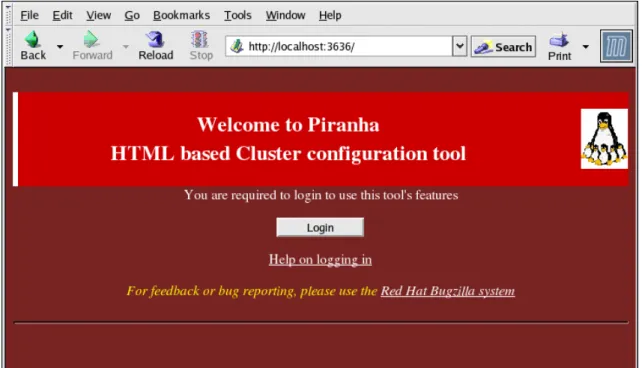
To use the Piranha Configuration Tool you need at minimum a text-only Web browser. If you start a Web browser on the primary LVS router, open the locationhttp://localhost:3636. You
can reach the Piranha Configuration Tool from anywhere via Web browser by replacing loc-alhostwith the hostname or IP address of the primary LVS router.
When your browser connects to the Piranha Configuration Tool, you must login to access the cluster configuration services. Enterpiranhain the Username field and the password set with
piranha-passwdin the Password field.
Now that the Piranha Configuration Tool is running, you may wish to consider limiting who has access to the tool over the network. The next section reviews ways to accomplish this task.
4. Limiting Access To the Piranha
Configur-ation Tool
The Piranha Configuration Tool prompts for a valid username and password combination. However, because all of the data passed to the Piranha Configuration Tool is in plain text, it is recommended that you restrict access only to trusted networks or to the local machine.
The easiest way to restrict access is to use the Apache HTTP Server's built in access control mechanisms by editing/etc/sysconfig/ha/web/secure/.htaccess. After altering the file you do
not have to restart thepiranha-guiservice because the server checks the.htaccessfile each
time it accesses the directory.
By default, the access controls for this directory allow anyone to view the contents of the direct-ory. Here is what the default access looks like:
Order deny,allow Allow from all
To limit access of the Piranha Configuration Tool to only the localhost change the.htaccess
file to allow access from only the loopback device (127.0.0.1). For more information on the loop-back device, see the chapter titled Network Scripts in the Red Hat Enterprise Linux Reference Guide.
Order deny,allow Deny from all Allow from 127.0.0.1
You can also allow specific hosts or subnets as seen in this example:
Order deny,allow Deny from all
Allow from 192.168.1.100 Allow from 172.16.57
In this example, only Web browsers from the machine with the IP address of 192.168.1.100 and machines on the 172.16.57/24 network can access the Piranha Configuration Tool.
Caution
Editing the Piranha Configuration Tool.htaccessfile limits access to the
configur-ation pages in the/etc/sysconfig/ha/web/secure/directory but not to the login and
the help pages in/etc/sysconfig/ha/web/. To limit access to this directory, create
a.htaccessfile in the/etc/sysconfig/ha/web/directory withorder,allow, anddeny
lines identical to/etc/sysconfig/ha/web/secure/.htaccess.
In order for the LVS router to forward network packets properly to the real servers, each LVS router node must have IP forwarding turned on in the kernel. Log in as root and change the line which readsnet.ipv4.ip_forward = 0in/etc/sysctl.confto the following:
net.ipv4.ip_forward = 1
The changes take effect when you reboot the system.
To check if IP forwarding is turned on, issue the following command as root:
/sbin/sysctl net.ipv4.ip_forward
If the above command returns a1, then IP forwarding is enabled. If it returns a0, then you can
turn it on manually using the following command:
/sbin/sysctl -w net.ipv4.ip_forward=1
6. Configuring Services on the Real Servers
If the real servers in the cluster are Red Hat Enterprise Linux systems, set the appropriate serv-er daemons to activate at boot time. These daemons can includehttpdfor Web services or xinetdfor FTP or Telnet services.
It may also be useful to access the real servers remotely, so thesshddaemon should also be
in-stalled and running.
Chapter 4. Setting Up a Red Hat
Enterprise Linux LVS Cluster
A Red Hat Enterprise Linux LVS cluster consists of two basic groups: the LVS routers and the real servers. To prevent a single point of failure, each groups should contain at least two mem-ber systems.
The LVS router group should consist of two identical or very similar systems running Red Hat Enterprise Linux. One will act as the active LVS router while the other stays in hot standby mode, so they need to have as close to the same capabilities as possible.
Before choosing and configuring the hardware for the real server group, you most decide what which of the three types of LVS topologies to use.
1. The NAT LVS Cluster
The NAT topology allows for great latitude in utilizing existing hardware, but it is limited in its ability to handle large loads due to the fact that all packets going into and coming out of the cluster pass through the LVS router.
Network Layout
The topology for an LVS cluster utilizing NAT routing is the easiest to configure from a work layout perspective because the cluster needs only one access point to the public net-work. The real servers pass all requests back through the LVS router so they are on their own private network.
Hardware
The NAT topology is the most flexible in regards to cluster hardware because the real serv-ers do not need to be Linux machines to function correctly in the cluster. In a NAT cluster, each real server only needs one NIC since it will only be responding to the LVS router. The LVS routers, on the other hand, need two NICs each to route traffic between the two net-works. Because this topology creates a network bottleneck at the LVS router, gigabit Ether-net NICs can be employed on each LVS router to increase the bandwidth the LVS routers can handle. If gigabit Ethernet is employed on the LVS routers, any switch connecting the real servers to the LVS routers must have at least two gigabit Ethernet ports to handle the load efficiently.
Software
Because the NAT topology requires the use ofiptablesfor some configurations, there can
be a fair amount of software configuration outside of Piranha Configuration Tool. In partic-ular, FTP services and the use of firewall marks requires extra manual configuration of the LVS routers to route requests properly.
public interfaces (eth0) will be on the 192.168.26/24 network (I know, I know, this is not a
rout-able IP, but let us pretend there is a firewall in front of the LVS router for good measure) and the private interfaces which link to the real servers (eth1) will be on the 10.11.12/24 network.
So on the active or primary LVS router node, the public interface's network script,/ etc/sysconfig/network-scripts/ifcfg-eth0, could look something like this:
DEVICE=eth0 BOOTPROTO=static ONBOOT=yes
IPADDR=192.168.26.9 NETMASK=255.255.255.0 GATEWAY=192.168.26.254
The/etc/sysconfig/network-scripts/ifcfg-eth1for the private NAT interface on the LVS
router could look something like this:
DEVICE=eth1 BOOTPROTO=static ONBOOT=yes IPADDR=10.11.12.9 NETMASK=255.255.255.0
In this example, the VIP for the LVS router's public interface will be 192.168.26.10 and the VIP for the NAT or private interface will be 10.11.12.10. So, it is essential that the real servers route requests back to the VIP for the NAT interface.
Important
The sample Ethernet interface configuration settings in this section are for the real IP addresses of an LVS router and not the floating IP addresses. To configure the public and private floating IP addresses the administrator should use the Piranha
Configuration Tool, as shown in Section 4, “GLOBAL SETTINGS” and
Sec-tion 6.1, “The VIRTUAL SERVER SubsecSec-tion”.
After configuring the primary LVS router node's network interfaces, configure the backup LVS router's real network interfaces — taking care that none of the IP address conflict with any other IP addresses on the network.
Important
Be sure each interface on the backup node services the same network as the in-terface on primary node. For instance, if eth0 connects to the public network on the primary node, it must also connect to the public network on the backup node as well.
1.2. Routing on the Real Servers
The most important thing to remember when configuring the real servers network interfaces in a NAT cluster is to set the gateway for the NAT floating IP address of the LVS router. In this ex-ample, that address will be 10.11.12.10.
Note
Once the network interfaces are up on the real servers, the machines will be un-able to ping or connect in other ways to the public network. This is normal. You will, however, be able to ping the real IP for the LVS router's private interface, in this case 10.11.12.8.
So the real server's/etc/sysconfig/network-scripts/ifcfg-eth0file could look similar to this: DEVICE=eth0
ONBOOT=yes BOOTPROTO=static IPADDR=10.11.12.1 NETMASK=255.255.255.0 GATEWAY=10.11.12.10
Warning
If a real server has more than one network interface configured with aGATEWAY=
line, the first one to come up will get the gateway. Therefore if botheth0andeth1
are configured andeth1is used for LVS clustering, the real servers may not route
requests properly.
It is best to turn off extraneous network interfaces by settingONBOOT=noin their
net-work scripts within the/etc/sysconfig/network-scripts/directory or by making
sure the gateway is correctly set in the interface which comes up first.
1.3. Enabling NAT Routing on the LVS Routers
In a simple NAT LVS cluster where each clustered service uses only one port, like HTTP on port 80, the administrator needs only to enable packet forwarding on the LVS routers for the re-quests to be properly routed between the outside world and the real servers. See Section 5, “Turning on Packet Forwarding” for instructions on turning on packet forwarding. However, more configuration is necessary when the clustered services require more than one port to go to the same real server during a user session. For information on creating multi-port services using firewall marks, see Section 4, “Multi-port Services and LVS Clustering”.
Once forwarding is enabled on the LVS routers and the real servers are set up and have the 1.3. Enabling NAT Routing on the LVS Routers
Warning
Do not configure the floating IP foreth0:1oreth1:1by manually editing network
scripts or using a network configuration tool. Instead, use the Piranha
Configura-tion Tool as shown in SecConfigura-tion 4, “GLOBAL SETTINGS” and SecConfigura-tion 6.1, “The
VIRTUAL SERVER Subsection” to configure any cluster-related virtual interfaces.
When finished, start thepulseservice as shown in Section 8, “Starting the Cluster”. Oncepulse
is up and running, the active LVS router will begin routing requests to the pool of real servers.
2. LVS Cluster via Direct Routing
As mentioned in Section 4.2, “Direct Routing”, direct routing allows real servers to process and route packets directly to a requesting user rather than passing outgoing packets through the LVS router. Direct routing requires that the real servers be physically connected to a network segment with the LVS router and be able to process and direct outgoing packets as well.
Network Layout
In a direct routing LVS setup, the LVS router needs to receive incoming requests and route them to the proper real server for processing. The real servers then need to directly route the response to the client. So, for example, if the client is on the Internet, and sends the packet through the LVS router to a real server, the real server must be able to go directly to the client via the Internet. This can be done by configuring a gateway for the real server to pass packets to the Internet. Each real server in the server pool can have its own separate gateway (and each gateway with its own connection to the Internet), allowing for maximum throughput and scalability. For typical LVS setups, however, the real servers can commu-nicate through one gateway (and therefore one network connection).
Important
It is not recommended to use the LVS router as a gateway for the real servers,
as that adds unneeded setup complexity as well as network load on the LVS router, which reintroduces the network bottleneck that exists in NAT routing.
Hardware
The hardware requirements of an LVS system using direct routing is similar to other LVS to-pologies. While the LVS router needs to be running Red Hat Enterprise Linux to process the incoming requests and perform load-balancing for the real servers, the real servers do not need to be Linux machines to function correctly in the cluster.The LVS routers need one or two NICs each (depending on if there is a back-up router). You can use two NICs for ease of configuration and to distinctly separate traffic — incoming requests are handled by one NIC and routed packets to real servers on the other.
Since the real servers bypass the LVS router and send outgoing packets directly to a client, 2. LVS Cluster via Direct Routing
a gateway to the Internet is required. For maximum performance and availability, each real server can be connected to its own separate gateway which has its own dedicated connec-tion to the carrier network to which the client is connected (such as the Internet or an in-tranet).
Software
There is some configuration outside of Piranha Configuration Tool that needs to be done, especially for administrators facing ARP issues when using LVS via direct routing. Refer to Section 2.1, “Direct Routing and arptables_jf” or Section 2.2, “Direct Routing and IPTables” for more information.
2.1. Direct Routing and
arptables_jfIn order to configure direct routing usingarptables_jf, each real server must have their virtual
IP address configured, so they can directly route packets. ARP requests for the VIP are ignored entirely by the real servers, and any ARP packets that might otherwise be sent containing the VIPs are mangled to contain the real server's IP instead of the VIPs.
Using thearptables_jfmethod, applications may bind to each individual VIP or port that the
real server is servicing. For example, thearptables_jfmethod allows multiple instances of
Apache HTTP Server to be running bound explicitly to different VIPs on the system. There are also significant performance advantages to usingarptables_jfover the IPTables option.
However, using thearptables_jfmethod, VIPs can not be configured to start on boot using
standard Red Hat Enterprise Linux system configuration tools.
To configure each real server to ignore ARP requests for each of the virtual IP addresses the Piranha cluster services, perform the following steps:
1. Create the ARP table entries for each virtual IP address on each real server (the real_ip is the IP the director uses to communicate with the real server; often this is the IP bound to
eth0):
arptables -A IN -d <virtual_ip> -j DROP
arptables -A OUT -d <virtual_ip> -j mangle --mangle-ip-s <real_ip>
This will cause the real servers to ignore all ARP requests for the virtual IP addresses, and change any outgoing ARP responses which might otherwise contain the virtual IP so that they contain the real IP of the server instead. The only node in the Piranha cluster which should respond to ARP requests for any of the VIPs is the current active Piranha LVS dir-ector node.
2. Once this has been completed on each real server, save the ARP table entries by typing the following commands on each real server:
service arptables_jf save
chkconfig --level 2345 arptables_jf on
3. Configure the virtual IP address on all real servers usingifconfigto create an IP alias. For
example:
# ifconfig eth0:1 192.168.76.24 netmask 255.255.252.0 broadcast 192.168.79.255 up
Or using theiproute2utilityip, for example: # ip addr add 192.168.76.24 dev eth0
As previously noted, the virtual IP addresses can not be configured to start on boot using the Red Hat system configuration tools. One way to work around this issue is to place these commands in/etc/rc.d/rc.local.
4. Configure Piranha for Direct Routing. Refer to Chapter 5, Configuring the LVS Routers with Piranha Configuration Tool for more information.
2.2. Direct Routing and IPTables
You may also work around the ARP issue using the direct routing method by creating IPTables firewall rules. To configure direct routing using IPTables, you must add rules that create a trans-parent proxy so that a real server will service packets sent to the VIP address, even though the VIP address does not exist on the system.
The IPTables method is simpler to configure than thearptables_jfmethod. This method also
circumvents the LVS ARP issue entirely, because the virtual IP address(es) only exist on the active LVS director.
However, there are performance issues using the IPTables method compared toarptables_jf,
as there is overhead in forwarding/masquerading every packet.
You also cannot reuse ports using the IPTables method. For example, it is not possible to run two separate Apache HTTP Server services bound to port 80, because both must bind to INAD-DR_ANYinstead of the virtual IP addresses.
To configure direct routing using the IPTables method, perform the following steps:
1. On each real server, run the following command for every VIP, port, and protocol (TCP or UDP) combination intended to be serviced for the real server:
iptables -t nat -A PREROUTING -p <tcp|udp> -d <vip> --dport <port> -j REDIRECT
This command will cause the real servers to process packets destined for the VIP and port that they are given.
2. Save the configuration on each real server:
# service iptables save
# chkconfig --level 2345 iptables on
The commands above cause the system to reload the IPTables configuration on bootup — 2.2. Direct Routing and IPTables
before the network is started.
3. Putting the Cluster Together
After determining which of the above routing methods to use, the hardware for the LVS cluster should be linked together on the network.
Important
The adapter devices on the LVS routers must be configured to access the same networks. For instance ifeth0connects to public network andeth1connects to the
private network, then these same devices on the backup LVS router must connect to the same networks.
Also the gateway listed in the first interface to come up at boot time is added to the routing table and subsequent gateways listed in other interfaces are ignored. This is especially important to consider when configuring the real servers.
After physically connecting together the cluster hardware, configure the network interfaces on the primary and backup LVS routers. This can be done using a graphical application such as system-config-network or by editing the network scripts manually. For more information about adding devices using system-config-network, see the chapter titled Network Configuration in the Red Hat Enterprise Linux Deployment Guide. For the remainder of the chapter, example al-terations to network interfaces are made either manually or through the Piranha Configuration Tool.
3.1. General LVS Networking Tips
Configure the real IP addresses for both the public and private networks on the LVS routers be-fore attempting to configure the cluster using the Piranha Configuration Tool. The sections on each topology give example network addresses, but the actual network addresses are needed. Below are some useful commands for bringing up network interfaces or checking their status.
Bringing Up Real Network Interfaces
To bring up a real network interface, use the following command as root, replacingNwith the number corresponding to the interface (eth0andeth1).
/sbin/ifup ethN
Warning
Do not use theifupscripts to bring up any floating IP addresses you may
con-figure using Piranha Configuration Tool (eth0:1oreth1:1). Use theservice
tails).
Bringing Down Real Network Interfaces
To bring down a real network interface, use the following command as root, replacingNwith the number corresponding to the interface (eth0andeth1).
/sbin/ifdown ethN
Checking the Status of Network Interfaces
If you need to check which network interfaces are up at any given time, type the following:
/sbin/ifconfig
To view the routing table for a machine, issue the following command:
/sbin/route
4. Multi-port Services and LVS Clustering
LVS routers under any topology require extra configuration when creating multi-port LVS ser-vices. Multi-port services can be created artificially by using firewall marks to bundle together different, but related protocols, such as HTTP (port 80) and HTTPS (port 443), or when LVS is used to cluster true multi-port protocols, such as FTP. In either case, the LVS router uses fire-wall marks to recognize that packets destined for different ports, but bearing the same firefire-wall mark, should be handled identically. Also, when combined with persistence, firewall marks en-sure connections from the client machine are routed to the same host, as long as the connec-tions occur within the length of time specified by the persistence parameter. For more on as-signing persistence to a virtual server, see Section 6.1, “The VIRTUAL SERVER Subsection”. Unfortunately, the mechanism used to balance the loads on the real servers — IPVS — can re-cognize the firewall marks assigned to a packet, but cannot itself assign firewall marks. The job of assigning firewall marks must be performed by the network packet filter,iptables, outside of
Piranha Configuration Tool.
4.1. Assigning Firewall Marks
To assign firewall marks to a packet destined for a particular port, the administrator must use
iptables.
This section illustrates how to bundle HTTP and HTTPS as an example, however FTP is anoth-er commonly clustanoth-ered multi-port protocol. If an LVS clustanoth-er is used for FTP sanoth-ervices, see Sec-tion 5, “FTP In an LVS Cluster” for details on how to best configure the cluster.
The basic rule to remember when using firewall marks is that for every protocol using a firewall mark in Piranha Configuration Tool there must be a commensurateiptablesrule to assign
marks to the network packets.
Before creating network packet filter rules, make sure there are no rules already in place. To do this, open a shell prompt, login as root, and type:
/sbin/service iptables status
Ifiptablesis not running, the prompt will instantly reappear.
Ifiptablesis active, it displays a set of rules. If rules are present, type the following command: /sbin/service iptables stop
If the rules already in place are important, check the contents of/etc/sysconfig/iptablesand
copy any rules worth keeping to a safe place before proceeding.
Below are rules which assign the same firewall mark, 80, to incoming traffic destined for the floating IP address,n.n.n.n, on ports 80 and 443.
/sbin/modprobe ip_tables
/sbin/iptables t mangle A PREROUTING p tcp d n.n.n.n/32 dport 80 j MARK --set-mark 80
/sbin/iptables t mangleA PREROUTING p tcp d n.n.n.n/32 dport 443 j MARK --set-mark 80
For instructions on assigning the VIP to the public network interface, see Section 6.1, “The VIR-TUAL SERVER Subsection”. Also note that you must log in as root and load the module for ipt-ablesbefore issuing rules for the first time.
In the aboveiptablescommands,n.n.n.nshould be replaced with the floating IP for your HTTP and HTTPS virtual servers. These commands have the net effect of assigning any traffic ad-dressed to the VIP on the appropriate ports a firewall mark of 80, which in turn is recognized by IPVS and forwarded appropriately.
Warning
The commands above will take effect immediately, but do not persist through a boot of the system. To ensure network packet filter settings are restored upon re-boot, refer to Section 6, “Saving Network Packet Filter Settings”
5. FTP In an LVS Cluster
File Transport Protocol (FTP) is an old and complex multi-port protocol that presents a distinct set of challenges to a clustered environment. To understand the nature of these challenges, you must first understand some key things about how FTP works.
5.1. How FTP Works
With most other server client relationships, the client machine opens up a connection to the server on a particular port and the server then responds to the client on that port. When an FTP
nection chosen by the client determines how the server responds and on what ports transac-tions will occur.
The two types of data connections are:
Active Connections
When an active connection is established, the server opens a data connection to the client from port 20 to a high range port on the client machine. All data from the server is then passed over this connection.
Passive Connections
When a passive connection is established, the client asks the FTP server to establish a passive connection port, which can be on any port higher than 10,000. The server then binds to this high-numbered port for this particular session and relays that port number back to the client. The client then opens the newly bound port for the data connection. Each data request the client makes results in a separate data connection. Most modern FTP clients at-tempt to establish a passive connection when requesting data from servers.
The two important things to note about all of this in regards to clustering is:
1. The client determines the type of connection, not the server. This means, to effectively cluster FTP, you must configure the LVS routers to handle both active and passive connec-tions.
2. The FTP client/server relationship can potentially open a large number of ports that the Piranha Configuration Tool and IPVS do not know about.
5.2. How This Affects LVS Routing
IPVS packet forwarding only allows connections in and out of the cluster based on it recognizing its port number or its firewall mark. If a client from outside the cluster attempts to open a port IPVS is not configured to handle, it drops the connection. Similarly, if the real server attempts to open a connection back out to the Internet on a port IPVS does not know about, it drops the connection. This means all connections from FTP clients on the Internet must have the same firewall mark assigned to them and all connections from the FTP server must be properly for-warded to the Internet using network packet filtering rules.
5.3. Creating Network Packet Filter Rules
Before assigning anyiptablesrules for FTP service, review the information in Section 4.1,
“Assigning Firewall Marks” concerning multi-port services and techniques for checking the exist-ing network packet filterexist-ing rules.
Below are rules which assign the same firewall mark, 21, to FTP traffic. For these rules to work properly, you must also use the VIRTUAL SERVER subsection of Piranha Configuration Tool to configure a virtual server for port 21 with a value of21in the Firewall Mark field. See
Sec-tion 6.1, “The VIRTUAL SERVER SubsecSec-tion” for details.
5.3.1. Rules for Active Connections
The rules for active connections tell the kernel to accept and forward connections coming to the 5.2. How This Affects LVS Routing
internal floating IP address on port 20 — the FTP data port.
The followingiptablescommand allows the LVS router to accept outgoing connections from the
real servers that IPVS does not know about:
/sbin/iptables -t nat -A POSTROUTING -p tcp -s n.n.n.0/24 --sport 20 -j MASQUERADE
In theiptablescommand,n.n.nshould be replaced with the first three values for the floating IP for the NAT interface's internal network interface defined in the GLOBAL SETTINGS panel of Piranha Configuration Tool.
5.3.2. Rules for Passive Connections
The rules for passive connections assign the appropriate firewall mark to connections coming in from the Internet to the floating IP for the service on a wide range of ports — 10,000 to 20,000.
Warning
If you are limiting the port range for passive connections, you must also configure the VSFTP server to use a matching port range. This can be accomplished by adding the following lines to/etc/vsftpd.conf:
pasv_min_port=10000
pasv_max_port=20000
You must also control the address that the server displays to the client for passive FTP connections. In a NAT routed LVS system, add the following line to/
etc/vsftpd.confto override the real server IP address to the VIP, which is what
the client sees upon connection. For example:
pasv_address=n.n.n.n
Replacen.n.n.nwith the VIP address of the LVS system.
For configuration of other FTP servers, consult the respective documentation.
This range should be a wide enough for most situations; however, you can increase this number to include all available non-secured ports by changing10000:20000in the commands below to 1024:65535.
The followingiptablescommands have the net effect of assigning any traffic addressed to the
floating IP on the appropriate ports a firewall mark of 21, which is in turn recognized by IPVS and forwarded appropriately:
/sbin/iptables t mangle A PREROUTING p tcp d n.n.n.n/32 dport 21 j MARK --set-mark 21
/sbin/iptables -t mangle -A PREROUTING -p tcp -d n.n.n.n/32 --dport 10000:20000 -j MARK
server defined in the VIRTUAL SERVER subsection of Piranha Configuration Tool.
Warning
The commands above take effect immediately, but do not persist through a reboot of the system. To ensure network packet filter settings are restored after a reboot, see Section 6, “Saving Network Packet Filter Settings”
Finally, you need to be sure that the appropriate service is set to activate on the proper run-levels. For more on this, refer to Section 1, “Configuring Services on the LVS Routers”.
6. Saving Network Packet Filter Settings
After configuring the appropriate network packet filters for your situation, save the settings so they get restored after a reboot. Foriptables, type the following command:
/sbin/service iptables save
This saves the settings in/etc/sysconfig/iptablesso they can be recalled at boot time.
Once this file is written, you are able to use the/sbin/servicecommand to start, stop, and
check the status (using the status switch) ofiptables. The/sbin/servicewill automatically load
the appropriate module for you. For an example of how to use the/sbin/servicecommand, see
Section 3, “Starting the Piranha Configuration Tool Service”.
Finally, you need to be sure the appropriate service is set to activate on the proper runlevels. For more on this, see Section 1, “Configuring Services on the LVS Routers”.
The next chapter explains how to use the Piranha Configuration Tool to configure the LVS router and describe the steps necessary to active an LVS cluster.