Contents:
Technical Information
30/72-8851-0 EN
FDTDevice Type Manager (DTM)
for AS800
1
Features / Application . . . 2
1.1 General . . . 2
2
Description of the AS800 Function Blocks . . . 3
2.1 Configuration . . . 4
2.2 Parameterisation. . . 6
2.3 Display of Measurements . . . 9
2.4 Simulation . . . 9
1 Features / Application
• Able to run in any FDT server environment according to FDT SPEC 0.98-1
• Supports AS800 HART devices
• Universal commands and common practice commands are supported
• Communication with the HART devices independently of system and fieldbus • Complete system integration into Symphony
1.1 General
With the AS800 DTM we offer you a convenient and user-friendly method for the diagnosis and parameterisation of AS800 field devices via HART protocol communication.
The AS800 DTM also communicates with all HART-capable devices available on the market using the universal and common practice HART commands. It is used for parameter display, configuration and diagnosis of HART-capable field and control room devices.
The AS800 DTM is a device type manager (DTM), and only operates within a field device tool environment accor-ding to FDT SPEC 0.98-1.
The application can be called by means of the function blocks listed below: • Configuration
• Parameterisation • Diagnostics
• Display of measurements
• Simulation
The character of a DTM, its function blocks, and the FDT server environment are described in the "FDT" specifi-cation.
The AS800 DTM consists of the following functions: • Display of the general device data from the database • Parameterisation of the general device parameters • Loading the parameters from the database
• Reading back the present configuration from the device • Online commands for setting limits to measuring ranges
• Online commands to reset the device and to burn EEPROM data • Online measurement display
• Simulation of the analog value
2 Description of the AS800 Function Blocks
The function blocks for configuration, parameterisation, measurement display, simulation and diagnosis are dis-played in consistent windows.
At the top of the window, the function block that has been called and the name of the component are displayed. Within the window, general information about the device is first displayed (manufacturer of the device, e.g. Hart-mann & Braun, type of the device, e.g. AF800). All further information depends on the function block.
2.1 Configuration
The configuration consists of 2 different file cards, one for general data and one for parameters. Both file cards are also used in the parameter assignment mode. The configuration data are automatically stored in the data-base.
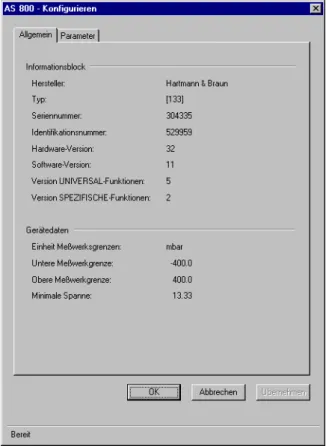
Fig. 1: Display of the general data file card:
Meaning of the displayed information:
Manufacturer Display of the device manufacturer from Table 8 of the HART - Smart
Communications Protocol common tables, Rev. 5.0
Type Device type
Serial number Serial number of the device
Identification number Identification number of the device
Hardware version Hardware version of the device
Software version Software version of the device
Version of the UNIVERSAL functions Revision number of the specification for the Universal Commands used as the basis
Version of the SPECIFIC functions Revision number of the specification for the device-specific document used as the basis
Unit of the measuring range limits Unit of the measuring range limits from Table 2 of the HART - Smart Communications Protocol common tables, Rev. 5.0
Lower measuring range limit Value of the lower measuring range limit
Upper measuring range limit Value of the upper measuring range limit
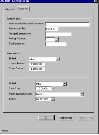
Fig. 2: Display of the parameter file card:
Meaning of the displayed information:
Measuring point identification Field for entry of the measuring point identifier with a maximum of 32 characters. Acceptable characters are upper case letters, numbers and special characters in accordance with the HART specification.
Bus identifier The bus identifier is entered here using a maximum of 8 characters.
Acceptable characters are upper case letters, numbers and special cha-racters in accordance with the HART specification.
Plant identifier The plant identifier can be entered using a maximum of 16 characters.
Acceptable characters are upper case letters, numbers and special cha-racters in accordance with the HART specification.
Polling address The polling address is needed if the device is operated on a bus
(Multid-rop).
An address between 0 and 15 is possible.
0=single device, 1-15=bus operation (current is set to minimum and cannot be changed, polling address 0 cancels the current limit)
Device number Serial number of the device
Unit of the measuring range limits Unit from Table 2 of the HART - Smart Communications Protocol com-mon tables, Rev. 5.0
Lower limit Value of the lower measuring range limit for the first measured value
Upper limit Value of the upper measuring range limit for the first measured value
Unit (free process variable) Select the unit for the free process variable. The unit set does not affect the analog output current!
The unit is part of Table 2 of the HART - Smart Communications Protocol common tables, Rev. 5.0
Damping The output signal from the transmitter can be damped by this function.
This can be very helpful if the input is fluctuating.
Transfer function Selectable transfer function
2.2 Parameterisation
The parameterisation consists of 3 different file cards, i.e. "General data", "Parameters" and "Commands" file card. It can only be performed online as communication is necessary between tool and device. Readout is effec-ted by the Upload all parameter which can arbitrarily be initiaeffec-ted online.
In contrast to the configuration function block, entered data are immediately written into the device.
Fig. 1: Display of the general data file card:
Meaning of the displayed information:
Manufacturer Display of the device manufacturer from Table 8 of the HART - Smart
Communications Protocol common tables, Rev. 5.0
Type Device type
Serial number Serial number of the device
Identification number Identification number of the device
Hardware version Hardware version of the device
Software version Software version of the device
Version of the UNIVERSAL functions Revision number of the specification for the Universal Commands used as the basis
Version of the SPECIFIC functions Revision number of the specification for the device-specific document used as the basis
Unit of the measuring range limits Unit of the measuring range limits from Table 2 of the HART - Smart Communications Protocol common tables, Rev. 5.0
Lower measuring range limit Value of the lower measuring range limit
Upper measuring range limit Value of the upper measuring range limit
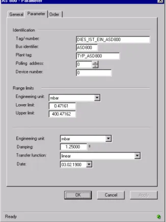
Fig. 2: Display of the parameter file card:
Meaning of the displayed information:
Measuring point identification Field for entry of the measuring point identifier with a maximum of 32 characters. Acceptable characters are upper case letters, numbers and special characters in accordance with the HART specification.
Bus identifier The bus identifier is entered here using a maximum of 8 characters.
Acceptable characters are upper case letters, numbers and special cha-racters in accordance with the HART specification.
Plant identifier The plant identifier can be entered using a maximum of 16 characters.
Acceptable characters are upper case letters, numbers and special cha-racters in accordance with the HART specification.
Polling address The polling address is needed if the device is operated on a bus
(Multid-rop).
An address between 0 and 15 is possible.
0=single device, 1-15=bus operation (current is set to minimum and cannot be changed, polling address 0 cancels the current limit)
Device number Serial number of the device
Unit of the measuring range limits Unit from Table 2 of the HART - Smart Communications Protocol com-mon tables, Rev. 5.0
Lower limit Value of the lower measuring range limit for the first measured value
Upper limit Value of the upper measuring range limit for the first measured value
Unit (free process variable) Select the unit for the free process variable. The unit set does not affect the analog output current!
The unit is part of Table 2 of the HART - Smart Communications Protocol common tables, Rev. 5.0
Damping The output signal from the transmitter can be damped by this function.
This can be very helpful if the input is fluctuating.
Transfer function Selectable transfer function
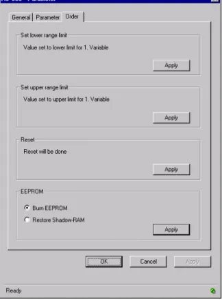
Fig. 3: Display of the commands file card
The commands file card consists of 4 command switches.
Set the lower measuring range limit The current process value is set as the lower measuring range limit for the first variable (see Display of Measurements). The command is sent to the device immediately, and is irreversible.
Set the upper measuring range limit The current process value is set as the upper measuring range limit for the first variable (see Display of Measurements). The command is sent to the device immediately, and is irreversible.
Reset command This command resets all the software in the device, which is
automati-cally started again. How the device behaves during the reset phase is not predictable, and depends on the particular device (see device des-cription). The reset process can take some time (device dependent).
EEPROM commands The EEPROM commands are used either to burn the device EEPROM
(burn EEPROM) with the current device data, or to restore the current data using the data saved in the EEPROM (restore shadow RAM). You can select between these two functions by means of the toggle function.
2.3 Display of Measurements
This function can only be executed when it is possible to establish communication with the field device. In the window area for the output current, the instantaneous output current is given as a percentage.
The measured values are displayed in milliamps. Up to 4 other measured values with their associated units are also displayed if these are supported by the devices.
2.4 Simulation
This function can only be carried out when it is possible to establish communication with the field device.
Simulation, setting a constant output current at the device, is used, for example, to test the signal lines or the adjusted limits.
The desired simulation current is entered either by the slider in the bar display or in the numerical input box. The mode toggle function allows switching between normal operation and constant current operation. The bar display shows the current that was read at selection.
Via the "Accept" button, the entered functions are taken over by the device, and the window is not closed. After clicking the "OK" button, the changes are transmitted to the device, and the window is closed. If the window is closed while simulation is active, a dialog box opens with the appropriate reminder that the device is still in con-stant current operation.
2.5 Diagnostics
This function can only be executed when it is possible to establish communication with the field device.
Diagnostics generate a display of the instantaneous device state by reading the status information. The data are read by clicking the "Read status" button. The status messages for the AS800 comprise EEPROM access, confi-guration data, measuring cell data, RAM, ROM and the EEPROM identifier.