Proceedings of the Workshop
Visual Formalisms for Patterns
at VL/HCC 2009
Design Pattern Modeling with Constraint Relaxation
Tam´as Vajk, Tam´as M´esz´aros and Tiham´er Levendovszky
12 pages
Guest Editors: Paolo Bottoni, Esther Guerra, Juan de Lara
Managing Editors: Tiziana Margaria, Julia Padberg, Gabriele Taentzer
Design Pattern Modeling with Constraint Relaxation
Tam´as Vajk, Tam´as M´esz´aros and Tiham´er Levendovszky
[tamas.vajk, mesztam, tihamer]@aut.bme.hu
Department of Automation and Applied Informatics
Budapest University of Technology and Economics, Budapest, Hungary
Abstract: Metamodeling is a widely applied technique in the field of graphical lan-guage engineering. Environments supporting metamodeling aid rapid and flexible domain-specific modeling language (DSML) definition and utilization. In software engineering, design patterns are efficient solutions for recurring problems. With the proliferation of DSMLs, there is a need for domain-specific design patterns to offer solutions to problems recurring in different domains. The aim of this paper is to illustrate a concept that integrates modeling patterns into a metamodeling en-vironment. The introduced approach utilizes the modeling functionalities of the environment; a visual design pattern metamodel, a system architectural metamodel extended with textual constraints are introduced. Furthermore, design patterns are validated against relaxed constraints defined in the metamodel to only allow the creation of patterns that can be extended to valid instance models.
Keywords:Design pattern, DSML, VMTS, OCL constraint, relaxation
1
Introduction
Design patterns in software engineering describe a problem that recurs, and then describe the core of the solution to that problem, in a way that the solution can be used many times, without ever doing it the same way twice [GHJV94]. In general, patterns have four essential elements: a name for identification, a problem description, the solution and the consequences, meaning the achieved results and trade-offs. As an example, a pattern ensuring that a class only has one instance with a global point of access is namedSingletonpattern. The solution (in C++) is to create a protected constructor, a private member variable that stores the globally unique instance and a static query method that instantiates the instance if it has not been already done, and returns it. And finally, as an example benefit of the use of this pattern is that it can have strict control over how and when clients access the sole instance. Together this four elements define a design pattern.
Design patterns aid rapid development only if the tool support is flexibly solved. Defining and reusing patterns should be seamless, otherwise users would remodel the pattern instead. Also, design-time validation should be available to support validated pattern development and inser-tion. A pattern is only valid, if it can be extended to an instance of the metamodel, this instance should satisfy all the hierarchical restrictions defined by the metamodel and none of the textual constraints should fail on it. We have developed tool support for domain-specific model pat-terns for our metamodeling and model transformation environment called Visual Modeling and Transformation System (VMTS). In our solution, the four essential elements of design patterns are integrated as follows: a name should be given for identification purposes, a pattern model is created as a solution and finally, problem statement and consequences can be explained in description fields.
Visual Modeling and Transformation System [VMT09] is a general purpose metamodeling environment supporting n-level metamodeling. N-level means in this context that the instance models can be used as metamodels: they can be used to define model hierarchies such as meta-class diagram - meta-class diagram - object diagram. The maximum depth of these hierarchies is not limited; we can construct an n-level modeling chain. VMTS uses a proprietary modeling space. Models in VMTS are represented as directed, attributed graphs. In our approach, edges are attributed as well.
The structure of this paper is as follows. Section2provides a brief overview of available mod-eling tools. Section3describes the design pattern development process in VMTS. Afterwards Section4details the hierarchical constraint relaxation in Section4.1 and the general OCL con-straint handling in Section4.2. Finally, we draw the conclusions and describe future research options in Section5.
2
Related work
There are several modeling and metamodeling frameworks that support domain-specific model-ing. The Generic Modeling Environment (GME) [LBM+01] is a highly configurable metamod-eling tool supporting two layers: a metamodel, and a modmetamod-eling layer. Diagram Editor Generator (DiaGen) [Min02] provides an efficient solution to create visual editors for DSLs. DiaGen is not based on metamodeling techniques, it uses its own specification language for defining the structure of diagrams. Eclipse [BBM03] is probably the most popular, highly extensible, open source modeling platform that supports metamodeling.
To the best of our knowledge, besides VMTS, only GME provides tool support for domain-specific design patterns to certain extent. However, there are several implementations and indus-trial applications that utilize patterns in UML environments.
Commercial applications, such as Rational Software Architect [IBM09], have the functionality to define and apply patterns in a productive environment, but these tools only support UML as modeling language, thus domain-specific patterns and models cannot be created.
simpli-fied. In the given solution, an UML profile has been provided to brand diagrams with stereotype information. Based on the attached information, the applied design patterns and the role of each element played in the pattern can be retrived from the system. The authors implemented a sys-tem, named VisDP, in which the augmented information is not only stored but visualized in a legible way. The complexity of the resulting diagrams are kept to a minimum based on several aspects. The given solution could be integrated into VMTS to aid domain-specific design pattern creation, however, our approach now deals with more fundamental problems, such as how to in-tegrate design patterns into a DSL environment, and how to force valid pattern definition. Thus, the UML related design pattern achievments given in [DYZ07] can be considered a future work for our domain-specific pattern solution.
The Design Pattern Modeling Language (DPML) [MHG02] is a high level language which is proposed to describe UML design patterns. With DPML one can model the static structure of a pattern, however, the approach also provides a solution to identify the usage of a pattern in the host model later as well. During the instantiation process, an instance model is created, that maps the elements of the pattern to the elements of the host model. Compared to DPML, our solution is not limited to UML, and we use the target domain and the concrete syntax to define patterns. Although, we do not create a reference between the pattern elements and the concrete instances of them. Furthermore, the focus of our research is to verify - at least partially - the constraints of the metamodel on the patterns, which issue is not handled by DPML.
The work presented in [ZKDZ07] provides solutions for two different problems: (i) it verifies whether a design observes the structural integrity of the pattern using spatial graph grammars. (ii) Furthermore, it offers graph transformation to evolve models by preserving the properties of the patterns: an individual graph transformation is suggested for each characteristic operations related to a design pattern. Although [ZKDZ07] is limited to UML class diagrams, the approach could be generalized to arbitrary modeling languages as well.
3
Design pattern modeling support in VMTS
As we are embedding design pattern support into a metamodeling environment, it is straightfor-ward to use the modeling environment and its data repository to create and store patterns as well. The simplest solution is to define patterns as general models, thus, we have a complete solution to store default model element properties and layout information together with the patterns as well.
In addition to defining design patterns, there is a natural need to organize them into categories, and attach meta information to them. For this purpose, we have created a simple language that can model the hierarchy of pattern categories, and the position of design patterns in this hierarchy.
3.1 Defining design patterns in VMTS
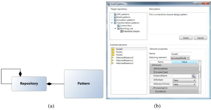
(a) Transitive closure (b) Registering design pattern
Figure 1: Design pattern definition in VMTS
contain edges with only one endpoint set, as the another endpoint can be set in the target model the design pattern is inserted into. Another criterion that can be checked less restrictively is the correspondence of the containment hierarchy to the one defined in the metamodel: when build-ing a model, the container node of an element has to be exactly of the type that was defined in the metamodel. However, when a design pattern is built, each element can also be placed directly onto the diagram, and we have to check at insert time, whether the target container is correct or not.
Figure 1illustrates a general transitive closure pattern for graph rewriting rules, and the in-terface to register a pattern in the central repository. When registering a design pattern, one can select among existing pattern categories for the container of the new element (or create a new category in the tree), and provide a name and description for the pattern.
3.2 Organization of design patterns
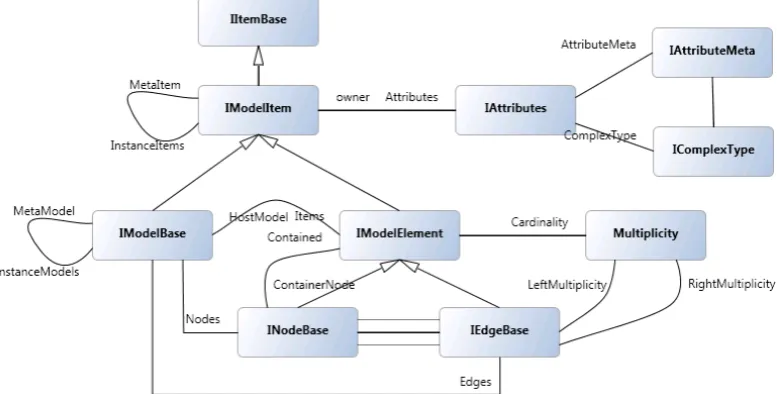
Design patterns can be organized into categories. These categories correspond to the elements of a unique model, its metamodel is depicted in Figure 2(a).
On the diagram, theRepository element corresponds to the categories. Repositories can be embedded into each other, and they can containPatterns. Each pattern contains aDescription
attribute, and aRe f erenceattribute pointing to a model that contains a design pattern.
3.3 Inserting patterns
Design pattern instances can be inserted into any target model, however, verifications have to be performed whether the pattern can be inserted into the selected context or not. The most important constraint is that the design pattern must have the same metamodel as the target model. Figure 2(b) depicts the window used to insert patterns into the target model. Design patterns with non matching metamodels are not even provided for insertion. Another important criterion is that the root elements of the pattern (the elements that are placed directly onto the diagram of the pattern model) should be able to be contained by the target element in the target model according to the metamodel.
(a) (b)
Figure 2: (a) Pattern repository metamodel (b) Pattern insertion window
When a design pattern is being inserted, it is common that several elements of the pattern are already defined by the target model. These elements are the connection points between the pattern and the target model. Therefore, VMTS also provides the possibility to select a matching target model element for pattern elements. Pattern elements with matching target model elements are not inserted again, but the remaining parts are glued to the existing ones.
4
Constraint relaxation
Restrictions applied to models can be divided into two categories: (i) general restrictions that the modeling environment forces onto the models and (ii) domain-specific constraints defined in the metamodels. The former ones can be considered domain independent constraints that are given by the tool-set of the environment. Generally, these are structural constraints, such as the disallowance of dangling edges. The latter ones are developed by the metamodel creator, these constraints are restrictions that cannot be defined visually by the metamodel. A platform-independent, standardized language for this purpose is the Object Constraint Language (OCL) [WK03].
During the pattern creation, constraint validation should be performed to filter invalid patterns. A pattern can be considered invalid, if there is no possible augmentation to create a valid instance model from it. The two types of constraint require different constraint relaxation approaches, which are introduced in the following sections.
4.1 Structural constraint relaxation
utilize previously implemented functionalities.
4.1.1 Interface hierarchy of VMTS Models
To utilize OCL constraints for validating general structural properties, such as cardinality, edge multiplicity or whether a model contains dangling edges or not, a technique is needed to define general constraints that do not correspond to a specific domain. Extending OCL with non-domain specific features would require changing the language definition, thus, this is not considered a viable solution. As illustrated in [AALa09], VMTS translates metamodels into C# class libraries that are instantiated when instance models are created. Naturally, the generated classes imple-ment a predefined interface hierarchy, called VMTS Domain Interface (VDI). To support domain independent constraints, this VDI has been modeled in VMTS as a standard domain-specific model, which is depicted in Figure3. The illustrated model gives the possibility to express con-straints that apply to all the domains, which implement the VDI. The modeled VDI hierarchy strictly follows the one used in the actual VDI implementation. Thus, for further reference see [AALa09].
Figure 3: Modeled VMTS Domain Interface (VDI)
General model constraints that can be expressed with standard OCL are integrated into VMTS. For example, during modeling, dangling edges should not be allowed, thus a constraint illustrated in Figure4is defined to enforce valid edges.
4.1.2 Constraint relaxation in pattern definition
context IEdgeBase inv DanglingEdge:
not self.Left.oclIsUndefined() and not self.Right.oclIsUndefined()
Figure 4: Dangling edge invariant
the multiplicities on the edges, the cardinalities of the nodes in the metamodel and allowing empty attributes [LLM]. In practice, this means that some of the general constraints should be changed, such as the multiplicity checking; some should be omitted, such as the dangling edge validation; and some may be left unchanged, such as enforcing model item naming conventions. Figure5 illustrates the constraint that validates edge multiplicities in design patterns. Note that the minimum multiplicity verification is omitted. In Line 3, the code iterates through all the nodes in the model. Line 4 selects an edge from theLeftEdges navigation. In Line 5, the metaedge of the selected edge is stored in a local variable (let expression). In Line 6, edges of the metaedge-type are counted from theLeftEdges. Finally, the previously computed value is compared to the upper value of the right multiplicity. The code fragment only checks the
LeftEdges navigation on thenode, similarly the RightEdgesnavigation should be validated as well.
1 context IModelBase
2 inv RelaxedEdgeMultiplicity: 3 self.Nodes->forAll(node | 4 node.LeftEdges->forAll(edge |
5 let mEdge: IEdgeBase := edge.MetaItem.oclAsType(’IEdgeBase’) in 6 node.LeftEdges->select(e | e.MetaItem = mEdge)->size() <= 7 mEdge.RightMultiplicity.MaxInt)
8 and ...)
Figure 5: Relaxed edge multiplicity checking
Similarly, Figure 6 depicts the relaxed cardinality validation constraint. The code fragment developed collects all the metamodel elements used in the current model into a set, and then the number of the instances are compared to the maximum value of the cardinality.
1 context IModelBase
2 inv RelaxedCardinality:
3 self.Items->collect(element |
4 element.MetaItem.oclAsType(’IModelElement’))->asSet()-> 5 forAll( meta |
6 self.Items->select(i | i.MetaItem = meta)->size() <= 7 meta.Cardinality.MaxInt)
4.2 Constraint relaxation
The structural constraint relaxation introduced above works only because the hierarchical relax-ation rules in patterns do not change based on the actual domain, but only on general restrictions, such as the allowance of dangling edges. However, metamodels are augmented with domain-specific constraints that should be enforced on the instance models. Thus, a mechanism is needed to handle OCL constraint relaxation as well. If a comprehensive method is given for OCL relax-ation, the development tool can force restrictions on the developed pattern to ensure that patterns that cannot be augmented to a conforming model cannot be created at all.
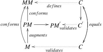
Figure7illustrates the general overview of the constraint relaxation.MMillustrates the meta-model,Mthe instance model,PMis the pattern model. PM0 marks a modified pattern on which the relaxedC0 constraints should be checked. PM0 is an extended version ofPM, in which each dangling edge is augmented with the appropriate end node. This is by no mean a restriction, as all the edges are typed, the types of the end nodes are well-known. Thus adding an element to the end does not cause any ambiguities. However, the constraint evaluation can be facilitated by pro-viding the evaluator as much information as possible. Figure7depicts the schematic overview of the constraint relaxation.
MM C
de f ines
oo
equals
PM
con f orms
OO
//PM0
C0
validatesoo
M
augments
OO
con f orms
GG
C
validates
oo
WW
Figure 7: General constraint relaxation overview
4.2.1 Relationship between OCL and relaxation
To handle OCL relaxation comprehensively, the relationship between OCL constraints and de-sign patterns should be examined. Figure 8depicts the basic structure of the OCL expression metalanguage.
Studying the figure reveals that the only point where an OCL code fragment interacts with the underlying model is theCallExp, more precisely, the FeatureCallExpnon-terminal of the language. AFeatureCallExpcan express attribute calls, navigations and method calls on model items.
4.2.2 Relaxation
Figure 8: OCL language overview
be further refined if the constraint is separated into several independent parts, and only those subexpressions are omitted that containFeatureCallExps. The separation can be implemented alongside Boolean operations, such asandoror, and possibly, lazy evaluation may not require the evaluation of undecidable expressions. However simple this method is, it is not useful in practice, as OCL constraints rarely omit model element retrieval, since the main aim of the con-straint is to restrict the models somehow.
Handling the model element access is a complex task, as different programming constructs react differently to a subpart that cannot be evaluated. For instance, in anif expression, if the condition is undecidable, the true and false branches should not be evaluated at all, and all the expressions that rely on this if have undecidable value. Unless, of course, the true and false branches contain the same evaluatable expressions. On the other hand there are cases, when there is no need to evaluate an expression on a pattern, for instance, consider the following expression:element.navigation→includes(expression). Ifnavigationis a navigation with 0..∗ multiplicity, the expressiondoes not need to be evaluated as the pattern is always amendable with a new item connected toelement that satisfies theexpression. Thus in this case, we can see thatincludesshould always returntrueon a pattern.
avail-able on OCL sets, their meanings and how they should be handled during constraint relaxation.
Method name Meaning Handling
size():int The size of the set Gives a lower bound
includes(T1):bool Whether the element is in the set Omit
excludes(T1):bool Opposite ofincludes Enforce
count(T1):int The number of occurrences of the
argu-ment
Gives a lower bound
includesAll(Set(T1)):
bool
Whether all the elements of the argument is in the set
Omit
excludesAll(Set(T1)):
bool
Opposite ofincludesAll Enforce
isEmpty():bool Whether the set is empty Enforce
notEmpty():bool Whether the set is not empty Omit
sum():T1 The sum of the elements if+exists onT1 No information
product(Coll(T2)) :
T3
The cross product of the two sets Gives a partial result
union(Set(T1)) :
Set(T1)
The union of the two sets Gives a partial result
intersect(Set(T1)) :
Set(T1)
The intersection of the two sets Gives an augmented result
minus(Set(T1)) :
Set(T1)
The elements of the set that are not in the argument
Gives a partial result
symmetricDi f f erence( Set(T1)):Set(T1)
The elements of the set that are in one of the sets
No information
including(T1) :
Set(T1)
The set with the argument union added to it
Gives a partial result
excluding(T1) :
Set(T1)
The set with the argument union sub-tracted from it
Gives a partial result
Table 1: OCL set methods and relaxation
In the third column of Table1, the following options are presented:
Gives a lower bound A number is returned and the evaluated constraint would give a smaller number than it would return on the instance model.
Omit The constraint validation can be omitted on the design pattern as the instance can always be augmented to returntrue.
Enforce The constraint validation should be enforced on the design pattern, if it returns f alse, the evaluation on the instance would return f alseas well.
Gives a partial result The method executed on the pattern returns a subset of the real result.
Gives an augmented result The method executed on the pattern returns a superset of the real result.
The last two can be considered undecidable as well, because in general we cannot state any-thing based on approximate results. Omitandenforceare straightforward. And the first option that states it gives a lower bound should be examined further. In this case, if we still consider that the set is a result of a navigation, the multiplicity of the navigation gives another restric-tion on the model. Thus the combinarestric-tion of the two multiplicity constraints should be utilized. Multiplicity relaxation states thatn1..n2 multiplicity should be changed to 0..n2, wheren2 can be infinity. The lower bound restriction (c1) coming from the constraint modifies it to c1..n2. Note that ifc1>n2, there cannot be any instance model that satisfies all the restrictions thus the pattern is not valid.
5
Conclusions and Future Work
This paper has presented an approach to treat domain-specific design patterns in metamodeling environments. The Visual Modeling and Transformation System has been utilized as the im-plementation framework. We have shown a way how a modeling environment can facilitate the design pattern definition, categorization and utilization. Also, structural constraints defined in the metamodels have to be partly checked in design patterns to allow only valid pattern definition. Thus, relaxed versions of general constraints are given in the modeling environment. Also, OCL constraints added to the metamodels should be considered during pattern validation, however, comprehensive handling requires complex program analysis. The given solution for supporting domain-specific design patterns reutilizes the modeling functionalities of the environment, thus, it requires only few modifications in the system, and integrates well into the environment.
Pattern integration in VMTS could be further improved by providing automatic gluing of patterns to the already existing model elements in the instance models. This requires common subgraph matching, as the most appropriate gluing options should be returned to the user. Also with drag and drop capabilities, this automatic gluing could be improved to aid pattern gluing to a specific subpart of the model. Constraint relaxation requires further examination. It would be highly useful to support the relaxation of iterator and iterate expressions. However, these programming constructs require a high level of program comprehension that has not been yet studied.
Acknowledgment
Bibliography
[AALa09] L. Angyal, M. Asztalos, L. Lengyel, et al. Towards a Fast, Efficient and Customizable Domain-Specific Modeling Framework. InProceedings of the IASTED International Conference. Volume 31, pp. 11–16. Innsbruck, Austria, February 2009.
[BBM03] F. Budinsky, S. A. Brodsky, E. Merks.Eclipse Modeling Framework. Pearson Educa-tion, 2003.
[DYZ07] J. Dong, S. Yang, K. Zhang. Visualizing Design Patterns in Their Applications and Compositions.IEEE Trans. Softw. Eng.33(7):433–453, 2007.
[GHJV94] E. Gamma, R. Helm, R. Johnson, J. M. Vlissides. Design Patterns: Elements of Reusable Object-Oriented Software (Addison-Wesley Professional Computing Se-ries). Addison-Wesley Professional, illustrated edition edition, November 1994.
[IBM09] IBM. Rational Software Architect website. 2009.
http://www-01.ibm.com/software/awdtools/architect/swarchitect/
[KT08] S. Kelly, J.-P. Tolvanen.Domain-Specific Modeling: Enabling Full Code Generation. John Wiley & Sons, March 2008.
[LBM+01] kos Ldeczi, rpd Bakay, M. Marti, P. Vlgyesi, G. Nordstrom, J. Sprinkle, G. Karsai. Composing Domain-Specific Design Environments.Computer34(11):44–51, 2001.
[LLM] T. Levendovszky, L. Lengyel, T. M´esz´aros. Supporting domain-specific model pat-terns with metamodeling.Software and Systems Modeling. accepted.
[MHG02] D. Mapelsden, J. Hosking, J. Grundy. Design Pattern Modelling and Instantiation using DPML. In Noble and Potter (eds.),Fortieth International Conference on Tech-nology of Object-Oriented Languages and Systems (TOOLS Pacific 2002). CRPIT 10, pp. 3–11. ACS, Sydney, Australia, 2002.
[Min02] M. Minas. Specifying Graph-like Diagrams with DiaGen. In Science of Computer Programming. P. 2002. 2002.
[VML08] T. Vajk, G. Mezei, T. Levendovszky. OCL Compiler Support for Modeling En-vironments with Incremental Compilation.Buletinul Stiintific al Universitatii ”Po-litehnica” din Timisoara53(1):19–24, 2008.
[VMT09] VMTS Team. Visual Modeling and Transformation System website. 2009.
http://vmts.aut.bme.hu
[WK03] J. Warmer, A. Kleppe.Object Constraint Language, The: Getting Your Models Ready for MDA, Second Edition. Addison Wesley, 2003.