Proceedings of the
Workshop on OCL and Textual Modelling
(OCL 2010)
Verified Visualisation of
Textual Modelling Languages
Fintan Fairmichael and Joseph R. Kiniry
18 pages
Guest Editors: Jordi Cabot, Tony Clark, Manuel Clavel, Martin Gogolla Managing Editors: Tiziana Margaria, Julia Padberg, Gabriele Taentzer
Verified Visualisation of
Textual Modelling Languages
Fintan Fairmichael1and Joseph R. Kiniry2
University College Dublin, Ireland1 IT University of Copenhagen, Denmark2
Abstract: Many modelling languages have both a textual and a graphical form. The relationship between these two forms ought to be clear and concrete, but is instead commonly underspecified, weak, and informal. Further, processes and tool support for modelling often do not treat both forms as first-class citizens, instead choosing to favour one as the “real” representation and the other as a derivable representation.
As textual and graphical forms have their individual strengths and weaknesses, ideally one should be able to view and edit a model in whichever form is most desirable at the moment. Furthermore, we should be able to do so without having to worry about semantic differences between what is seen in a graphical view versus what is seen in a textual view. If we are to develop tools that allow dual-editing— simultaneous editing of both the textual and graphical forms—then it is essential that their relationship is clearly and precisely defined.
This paper details a formal relationship between the textual and graphical forms of a high-level modelling language called the Business Object Notation (BON). We describe the semantics of the graphical and textual representations and the relation-ship that holds between them. We also formally define a view on an underlying model as an extraction function, and model diffs as a means of tracking changes as a model evolves. This theoretical foundation provides a means by which tools guarantee consistency between textual and graphical notations, as well shows how to efficiently perform model updates, reason about model views, and interpret prop-erties between modelling perspectives.
Keywords:textual modelling, graphical modelling, consistency, formalisation
1
Introduction
A wide variety of modelling languages and tools are now available to developers. For those languages that have both graphical and textual representations, it is essential that these are con-sistent such that the text that appears in the textual form and the dots, lines and shapes that are drawn for the graphical form are semantically equivalent or consistent.
The specification of the relationship between the textual and graphical forms of a modelling language should be more than the reference implementation of a tool that converts from one to the other.
in our graphical editor, a classAshould also be added to our text, and vice versa. It is crucial that both forms are updated accurately and kept in sync. If no synchronisation guarantees are made, then the model a user is viewing in one or other representation may not be accurate, leading to a plethora of potential issues as development continues.
Frequently, each form represents a different subset of the overall model. For example, the Object Constraint Language (OCL) for UML has no graphical representation. OCL annotations are simply encoded in UML diagrams using unstructurednotesor semi-structuredstereotypes. Similarly, most graphical forms contain some layout information that is not expressed in the cor-responding textual notation. Since we are concerned with the interrelationship and interactions of the two formats, in these cases we simply consider the subset of each form that is relatable, as the matter of maintaining this extraneous information is one of careful engineering.
By formalising the textual and graphical models of BON, and the relationship between them, we provide a precise notion of consistency between these two representations. By also formalis-ing the notion of a view on a model, we are able to examine some common views, how they relate to the original model, and their translation from one representation to another. Before looking in detail at this formalisation, we first discuss our modelling language of choice, BON.
1.1 BON
The Business Object Notation (BON) was developed from within the Eiffel community, back in the late 1980s and early 1990s, as a descriptive method that addresses both analysis and design issues [Ner92]. In fact, much of its syntactical style is inherited from the Eiffel programming language.
BON has twolevels, which are loosely referred to as the informal and formal levels. Diagrams at the informal level are comprised of natural language, written in a highly structured man-ner. At the formal level we have dependent types, including behavioural contracts on features1 (preconditions/postconditions) and classes (invariants). Inheritance (with generics and multiple superclasses) and client relations (associations and aggregations) are also expressed at the formal level.
Classes are hierarchically arranged in clusters, which are structures that simply group together one or more classes and/or clusters. Clusters are similar to packages in Java, except without the additional effects on visibility that packages exert. A well-formed model in BON must have a single top-level cluster—thesystem cluster.
Classes and clusters are described in the static part of a BON model, but there are also dynamic diagrams that allow one to describe events and scenarios over the static system. In this work we are concentrating on the static and formal parts of BON, although broadening it to cover the entire modelling language is a natural extension.
BON models have both a textual and a graphical form, with a one-to-one structural map-ping between them. The BON authors also describe interesting views on models, through the use of compressions—representing a set of graphical or textual elements with a simpler element [WN95]. This is standard practice in many graphical systems as a user zooms out, and similar techniques are employed through outline views and folding for textual editors. However,
1Features in BON can be thought of as methods or fields, but are more general than these and can potentially be
when dealing with a modelling language, the meaning of these simpler elements is important in the context of the elided elements that they represent. It is made all the more interesting in BON, as we can write and display relationships between clusters, as an abstraction from the underlying classes upon which the relationships really exist. We discuss this further inSection 3.3.3.
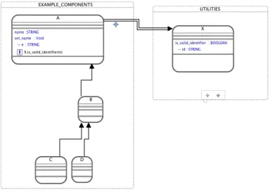
static_diagram EXAMPLE component
cluster EXAMPLE_COMPONENTS component
class A feature
name: STRING
set_name: Void -> n:STRING
require X.is_valid_identifier(n)
end end
class B inherit A end class C inherit B end class D inherit B end B client UTILITIES.X
end
cluster UTILITIES component
class X feature
is_valid_identifier: BOOLEAN
-> id:STRING end
end end
Listing 1: A static diagram in Textual BON
Listing 1shows an example of a textual BON model, which contains several classes linked through inheritance and a single client relation. The same model represented in graphical BON is shown inFigure 1.
1.2 Tools
1.2.1 BONc
We have previously developed a parser, typechecker and documentation generator for BON, the
BONc tool.2 It is open source, and available as a command line tool or as an Eclipse plugin. We have used BONc as a foundation for a number of projects, including a model-code consistency checker and the BON IDE.
1.2.2 BON IDE
We have recently developed a prototype visual editor for BON, built on top of the Eclipse Plat-form, leveraging the Eclipse Graphical Modeling Project (GMP) tools [Ski10].
A BON metamodel is defined using the Eclipse Modeling Framework Project (EMF) Ecore metamodel. Defining the BON metamodel as an Ecore model empowers the use of the Eclipse GMP and Graphical Editing Framework (GEF) to aid in the development/generation of tools for manipulating graphical BON. The culmination of these efforts is a graphical editor for BON— the BON IDE. The screenshot previously shown inFigure 1is taken of the BON IDE in action. The BON IDE checks the validity of a graphical BON model through constraints expressed in the Ecore metamodel, with additional validity expressions written in theChecklanguage (part of theModel To Text (M2T)3Project).
The remainder of this paper is organised as follows. The next section describes the formalisa-tion of graphical and textual BON models, the translaformalisa-tion between these, as well as views on a model. Section 3discusses some uses of our setup, in particular tracking model evolutions and keeping models synchronised. We next discuss related work, before finally drawing conclusions about the current state and future directions of this work.
2
Model Formalisation
We have mechanically formalised our textual and graphical models in higher-order logic using the PVS Specification and Verification System [ORS92]. Much of the formalisation is presented here in standard mathematical syntax (i.e., the reader need not be familiar with PVS to understand our theory), but several small examples of PVS are given as well to concretise our mechanisation. The motivated reader is welcome to download the full mechanisation viaour website.4
PVS provides an interactive proof checker for proving the correctness of theorems as well as type-correctness of the input specifications. By mechanising our theory in PVS we are able to assert desirable properties of our specification in a manner that is easily independently verified by others.
2.1 Graphical Formalisation
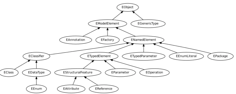
Due to our use of the Eclipse Modeling Framework [The10] it was first necessary to describe the core Ecore types, and their type hierarchy. The relevant parts of this type hierarchy are depicted inFigure 2.
BON types are defined as subtypes of the relevant Ecore constructs, summarised inFigure 3. A formal definition of several elements of this type hierarchy are necessary. Types that are not mentioned below have mechanisations but are irrelevant to the focus of this paper.
Definition 1(Basic Constructs) Asystemis a BON model instance. Aclassis a named concept or idea in a system. Aclusteris a named set ofclassesand sub-clusters. Every system has exactly one cluster denoted as thesystem cluster.
3 http://www.eclipse.org/modeling/m2t/?project=xpand
EObject
EModelElement EGenericType
EAnnotation EFactory ENamedElement
EClassifier ETypedElement ETypedParameter EEnumLiteral EPackage
EClass EDataType
EEnum
EStructuralFeature EParameter EOperation
EAttribute EReference
Figure 2: Ecore type hierarchy.
EClass
Abstraction Model
StaticAbstraction
Cluster BONClass
StaticRelationship Feature IndexClause InheritanceClause FeatureArgument PreCondition PostCondition Invariant
InheritanceRel ClientSupplierRel
AggregationRel AssociationRel RelationshipType EEnum
ImplementationStatus
We denote classes with the metavariable C, clusters with D, and the system cluster as S. Functions on classes and clusters exist for extracting the relevant attributes (e.g., identifier, list of features, etc.), but are not discussed further here.
Informally, a BON model consists of a set of classes, a set of clusters, and a set of relations between these classes and clusters. The general idea is that inheritance relations define the sub-typing relations between classes, cluster relations give the clustering structure of the system, and client relations state dependencies between the classes in the system. Each of these constructs, in turn, is formalised in the following.
The inheritance, cluster, and client relations of a system are all dependently typed directed graphs (“digraphs” within PVS). An inheritance graph is more precisely atreeofBONClasses, rooted with theANYclass.5
Definition 2 (Inheritance Tree) An inheritance tree is a (directed) tree whose vertices are elements of the typeBONClassand whose root is theBONClass ANY.
This definition is expressed in PVS in the following fashion.
ANY: BONClass
i n h e r i t a n c e t r e e : TYPE =
{ t : T r e e [ BONClass ] | r o o t ? ( t ) (ANY) }
This PVS specification states that the constant ANY is of type BONClass and the simple dependent typeinheritance treeis a tree ofBONClasses whose root vertex isANY.
Acluster graphis also a tree, with the system cluster at its root. SinceStaticAbstraction
is subtyped by both theClusterandBONClasstypes, we thus useStaticAbstractions as the vertex type in our cluster tree.
Definition 3 (Cluster Tree) Acluster treeis a directed tree CT ofStaticAbstractions where the root of CT is the system cluster, and every non-root vertex in CT has exactly one clusteras its parent.
The last condition within this definition is necessary to insist that only clusters may contain other static abstractions (i.e., classes must be leaf vertices within the cluster graph), and every static abstraction is directly contained within one cluster (except the system cluster).
Definition 4(Client Graph) Aclient graphis a directed graph ofBONClasses. Each edge in the graph is a client relation.
Note that, as no further constraints are placed on the client graph, cycles are permitted—as would be expected for client relations.
ABON modelis comprised of an inheritance tree, a cluster tree and a client graph. Addition-ally, all classes in the system must appear as vertices in both the inheritance tree and the cluster tree, and no other classes may appear in the client graph. The metavariable used to denote aBON modelisM.
Definition 5(BON Model) ABON modelis a record[IT,CT,CG]where:
• IT is aninheritance tree,CT is acluster tree, andCGis aclient graph,
• the set ofBONClasses that are vertices inCT must be equivalent to the set of vertices in IT,
• and the set ofBONClasses that are vertices inCGmust be a subset of those appearing in CT/IT
This definition is expressed within PVS by declaring the record type and a predicate that determines if such a record meets the latter two criteria above. TheBON modeltype is then the subset of these records that satisfies this predicate.
BON mode l rec : TYPE = [ # i t : i n h e r i t a n c e t r e e ,
c t : c l u s t e r t r e e , cg : c l i e n t d i g r a p h # ]
BON model ? (m: BON mode l rec ) : b o o l = v e r t (m‘ i t ) = c l a s s v e r t (m‘ c t ) AND
s u b s e t ? ( v e r t (m‘ cg ) , v e r t (m‘ i t ) )
BON model : TYPE = ( BON model ? )
2.2 Textual Formalisation
BON textual models are represented as atype context. Classes are stored in the type context in a partial function from aFormalClassTypeto aFormalClassDefinition. The function is partial, as it only returns a class definition when such has been given in the system and stored in the type context. Asking for the definition of a class type that is not present in the type context returnsbottom.6 The metavariablesCT andCDdenoteFormalClassTypes and Formal-ClassDefinitions, respectively.
AFormalClassTypecontains the identifier that denotes the class in question and a list of generic parameters for the type it represents. Thetype function extracts the type from a given class definition:type:CD→CT.
Definition 6 (Class Definition Map) A class definition mapCDM is a partial functiondef : CT0→CDwhere:
• CT0is a subset ofCT and
• ∀ct0∈CT0:type(de f(ct0)) =ct0.
The second condition in this definition ensures that class types are only mapped to class def-initions that actually have the type in question.
Clusters are similarly stored in a partial function fromFormalClusterTypeto Formal-ClusterDefinition. We omit the precise definition for brevity.
TypeRelationPairs are used to represent the various relations between types in a system with subtypesInheritanceRelation,ClusteringRelationandClientRelation. In our PVS mechanisationTypeRelationPairis anabstract datatypewith these three sub-types.7
Using all of this mathematical infrastructure, one can now defineBON textual type contexts.
Definition 7(Type Context) A BON textualtype contextis a record[CDM,CLDM,S,R]where CDM is a class definition map,CLDM is a cluster definition map,S is the system cluster type, andR is a set ofTypeRelationPairs.
As usual, the metavariable Γ denotes a BON textual type context, and the sentence Γ`
indicates thatΓis well-formed.
Type contexts are created and reasoned about with a standard suite of operations that guarantee they remain well-formed and consistent. As is normal, our formalisation of type contexts only permits types (i.e., classes and clusters) to beaddedto the context, notremoved, at this time.
2.3 Relating Textual and Graphical Formalisations
Next comes the meat of the matter: relating the theory oftextualBON to the theory ofgraphical BON.
The key idea here is that one incrementally defines a semantics-preserving bijective function, called amodel interpretation, that maps from a well-formed textual type context to a well-formed graphical type context. As the function is bijective, it implicitly defines an equivalence class between (pairs of elements in) the contexts, and hence between contexts’ contents (classes and clusters). Moreover, since the interpretation is semantics-preserving, any property proven about constructs at one end of the interpretation can be “pushed” through the interpretation to its other end.
Providing the details of this interpretation is beyond the scope of this paper. The interested reader should obtain the PVS source and look, in particular, at the theoryviz to typesystem. This theory contains about a dozen critical lemmas, of which we have mechanically proven half at this time, and sketched out proofs of the other half by-hand.
Commonly, one only defines this kind of interpretation as a model relation; but, as we have carefully crafted the theories at both ends of the relation, we have also defined “executable” interpretation functions that go “both ways,” from graphical to textual and vice versa.
Mathematically, this is unsurprising and not necessarily terribly useful. But practically, the existence of these functions is extremely useful, as any well-formed type context created with a tool realising either side of the relation (i.e., whether a developer draws a picture or writes a
7Abstract Datatypes in PVS automatically generate additional axioms. This includes an axiom that each type must
textual specification that describes a system) can be interpreted into the dual semantic domain. Performing the defined conversion in PVS involves applying the relevant functions to rewrite a model from one representation to another. As such, the conversion scales to large models, although the number of intermediate steps in the conversion may grow with the model size. A textual specification is “rendered” into a graphical specification, and it is guaranteed that all properties of the textual specification are captured in the graphical specification. Likewise, a graphical specification is “pretty-printed” into a textual specification, and the same semantic guarantees hold.
Finally, the relation itself is useful as it permits one to check that two specifications, graphical and textual, areconsistentwith each other and if one is arefinementof the other.
Definition 8 (Consistent Models) A (graphical) BON modelM isconsistent witha (textual) type contextΓiff there exists a quintuple of maps between classes, clusters, systems, and
rela-tions that are bijecrela-tions. We writeM ∼=Γif this is the case.
Definition 9(Refinements as Submodels) A modelM is arefinement of a type contextΓiff
there exists a quintuple of maps between classes, clusters, systems, and relations fromM toΓ
are surjections. We writeM AΓif this is the case. This definition is symmetric.
Now that we can compare textual and graphical specifications, and understand what it means to refine between them, we must reflect on the kind of operations that we can perform to either end of the interpretation, and what each of those operations means in the dual domain. The first operation of interest is views, as it is not always the case that one wishes to render an entire graphical model.
2.4 Views
We can informally define a view as the display of a subset of the elements (classes, clusters, relations) in a model. In order to formally define a view, we first define the type of a (generic) model view. Amodel viewis a “slice” of a model amenable to visualisation. As our models have three components—inheritance and cluster hierarchies and a client relation graph—a view slices through all three components.
Definition 10(BON Model View) ABON Model Viewfor aBON Model[IT,CT,CG](recall Definition5) is a record[ITv,CTv,CGv]whereITv is a (possibly empty) subgraph ofIT (resp.
CTvandCT, andCGvandCG).
The metavariable we use for theBON Model Viewtype isV, and we denote the corresponding relation as6:M×V.
A relation is expressed in PVS in one of several ways. We have chosen to formalise this relation as a (curried) function with a codomain of type boolean.8 The definition is based upon a
8In PVS, the declaration of a functionF of typeA×B→Cis denoted asF(A,B):C, in which case any use of
case distinction on all subtypes ofV. The function type definition in PVS is shown below.
BON model view ? (m: BON model ) ( v : B O N m o d e l v i e w r e c ) : b o o l
Using a curriable representation enables us to define a type for all legal views of a given model. We do so by defining a dependent type of a view function that takes aBON modeland returns a valid view for the given model.
Definition 11(The View Type) TheView TypeVM is a function type dependent upon a model
mand is of typem:M →(v:V|m6v).
Such a dependent type is realised in PVS by the following type declaration. Note that the codomain is the type of all views onm.
v i e w : TYPE = [m: BON model −> ( BON model view ? (m ) ) ]
3
Uses
3.1 Model Evolution
As models change over time, keeping track of those changes and maintaining the consistency of the graphical and textual forms is crucial. We will first define a few relevant functions on graphs, leading up to a definition of adiff on a pair of BON models.
Definition 12(Graph Merge) A graph merge is a functiongm:G×G →G that produces a graph that contains a union of the vertices and edges from the two input graphs.
The difference of two graphs is a new graph with vertices as the difference of the two input graphs’ vertices, and edges as the difference of the two input graphs’ edges.
Definition 13(Graph Difference) Agraph differenceis a functiongd:G×G →G, such that the resultant graph contains all the edges and vertices that are contained in the first of the input graphs, but not in the second.
Amodel difference record,MD, is a record[ITd,CTd,CGd]whereITd is a directed graph of
BONClasses,CTdis a directed graph ofStaticAbstractions andCGdis a directed graph ofBONClasses. Model difference records are used to store the output of a model difference.
Definition 14(Model Difference) The model differencefunctiondifference:M×M →MD
creates a record containing the graph differences of each of the constituent graphs of the input models.
Amodel differencegives us what was present in the first model and not in the second—i.e., the elements that are removed when translating from the first model to the second. However, we
also need to know what was present in the second model but not in the first (the elements that were “added”).
Definition 15(Model Diff) Themodel diff function for input modelsm1,m2produces a record
[add,rem], whereadd=difference(m2,m1)andrem=difference(m1,m2).
This is akin to the diff file comparison utility that represents the changes between two files through the parts that are added and the parts that are removed. We now define a diff application function for BON models that “applies” a diff to a given model.
Definition 16(Model Diff Application) Themodel diff applicationfunctionapply diff :M×
MD→M creates a new model produced by adding all elements in theaddfield of the model diff and removing all elements in theremfield.
Technically the output of a model diff application is a BON model record, as the diff used might produce an invalid BON model. In PVS this means that we produce aBON model rec
that does not necessarily satisfy the predicateBON model?. We could of course define a pred-icate that tells us if a given input model and model diff would produce a valid model through apply diff, but this is not likely to be more useful than simply applying the diff and then seeing if the result is a valid model.
One essential property of theapply diff anddiff functions is that
apply diff(m1,diff(m1,m2)) =m2
That is, if we take the diff of two models, and apply this diff to the first of those models we should produce the second model. This property is intuitive from the understanding that a diff describes the changes that must be made to the first input model to produce the second.
It is possible to define a bijective translation of the BON graphical model diff to a (similarly defined) textual diff that operates on the BON textual model, allowing updating of the textual model from the graphical model (and similarly the graphical model from the textual model) by computing the diff for the changes, translating this diff and applying it to the textual model. This removes the need to translate the full model every time we want to synchronise our two model forms.
3.2 Chasing Refinements
Given the relation and functions defined in Section2.3, there are a number of interesting prop-erties we can “push” between worlds. In essence, much like in theoretical physics and other branches of mathematics involving symmetries, sometimes it is easier to state or reason about a property in one theory than another.
3.2.1 The Right Tool Principle
Certain activities, like brainstorming or sketching out an architecture, are often better accomp-lished in one tool (e.g., a graphical model editor, like the BON IDE) than another. Since an interpretation exists between domains, generating a complete, human-readable, consistent text-ual specification from a “sketch” of a system is trivial.
We call this idea “the right tool” principle—one should not be prevented from using the right tool for the job and one should be able to leverage such work in both domains.
3.2.2 Difficult Properties
At first blush, the idea of awell-formed graphical model seems simple enough. But we found encoding such in a framework as complex as the EMF+GEF to be fraught with peril. On the other hand, defining such a property in the textual model is a straightforward proposition. Con-sequently, we do not bother attempting to specify complete and complex well-formedness con-ditions on a graphical model, we simply translate from the graphical to the textual and check well-formedness there.
3.2.3 Axiomatic Properties
Axiomatic properties like well-formedness are delicately realised in textual and graphical tools. Whenshouldsuch properties hold, and whenmustthey hold? In our experience, too many tools, especially those with formal underpinnings, improperly force consistency-like properties.
For example, many modern compilers are able to successfully compile erroneous programs by making assumptions about developer intent and performing runtime error correction of the input program. Of course, they issue warnings in such cases, but overall this behavior makes the tools easier to use and more robust. The Java compiler included with the Eclipse IDE is an excellent example. Eclipse can perform type-completion and summarise a class in the outline view even if the program code in the editor is not type-correct.
As another example, while using a tool like the BON IDE, often it is not justuseful, but is nec-essaryto draw aninconsistentorill-formedmodel. Perhaps such happens during brainstorming; perhaps in a few more steps the model will be consistent again; perhaps the designer is modelling an existing system which, by virtue of its very definition, is inconsistent in the first place.
By formally defining such properties on either side of the interpretation and understanding precisely when reasoning infrastructure depends upon their validity, we are able to characterise how and when to enforce them. Within PVS we realise such a theoretical trick by putting prop-erties that arestrictlynecessary for reasoning within the definitions of our predicate types, while those that are optionalare encoded as axioms or lemmas. If a definition of a formula F that is used to reason about a model, or proofs relating to such a formula, does not involve a given axiom or lemmaP, then we knowFandPto beindependent, and as such isoptional.
3.3 Views
Figure 4: Code folding in the Eclipse Java editor.
section discusses a couple of more interesting views commonly provided for textual models, and explores what should happen to relationships involving elements that are hidden in a view (i.e., present in the original model, but not in the view).
3.3.1 Outline View
Outline views of textual modelling languages typically give a hierarchical view of the principal elements in the model. It is clear that an outline view is indeed a view, under our definition, since the hierarchies in question are present in the original model. Outline views are less common for graphical editors, but the principle remains the same and can be provided in a similar manner.
3.3.2 Folding
Another common feature with modern textual editors is folding. This is where a large, multi-line element can be collapsed in the view to a single line. For instance, a class definition that normally spans dozens of lines can be collapsed to just one line. Typically a small graphical widget in the left margin of the line denotes the folding state of an element, as well as to function as a button for the fold and unfold operations. An example of code folding in the Eclipse Java development tools (JDT) source editor is shown inFigure 4. Here a method body (lines 8–13) has been hidden from view, with graphical artifacts to indicate this to the user.
Collapsing or restoring a foldable element are relatively straightforward alterations to the view on a model. When an element is collapsed, the view has been altered so that sub-elements in the hierarchical structure of the original model are ellided from the view.
3.3.3 Relationships Involving Hidden Elements
Folding is related to compression in BON, as previously discussed inSection 1.1. When one performs folding, compression, or some other view adjustment where model elements are being hidden as a means of providing a simplified or abstracted view of the system, it raises an inter-esting question as to what should happen to the relationships that exist between model elements that are hidden. In the case where model elements are hidden because they are not relevant, then of course no relationships involving these elements should appear in the view.
Figure 5: Graphical BON compression example (from [WN95]).
to appear at the cluster level.
It is this type of view that the BON authors were keen to support. Figure 5shows a simple example of an inheritance relationship that has been abstracted from the underlying classesB,C,
D,E, to their containing clusterCHILDREN.
How to amend our definition of a view of a model, such that it can accommodate this “pulling up” of relationships to higher-level abstractions, is an ongoing research question for us.
4
Related Work
There is a great abundance of related work on modelling languages and tools that deal with textual and graphical representations, so we will only briefly mention a few of those that are relevant.
Lancaric et al. developed a case tool for BON that supported drawing and editing of graphical BON class diagrams (static) and dynamic diagrams [LOP02,PKOL02]. The graphical repre-sentation they used largely followed that originally set out by Walden and Nerson. Skeleton code generation is possible to the target languages of Eiffel, Java with JML, and textual BON. Importing existing BON models is not supported, so round-tripping during development is not possible.
Goguen’s early work on formal semiotics [Gog99] and Feferman’s work on reasoning with diagrams [Fef10] has been inspirational to our work. Both researchers argue, in essence, that only by connecting the formal world (of which computing, and thus system design, is definitely one of the most complex examples thereof) with a grounding in social reality via semiotics, or the general theory of signs, can one effectively communicate complex constructs in effective ways. Moreover, proofs appealing to diagrams and other semiotic constructs are ubiquitous in geometry, number theory, and especially category theory.
UML-B is a profile of UML, which defines a subset and specialisation of UML that has a map-ping to, and is therefore suitable for, translation into the (textual) B language [SB06]. Although an equivalency of UML features to B structures is defined, this work is differentiated by the fact that UML-B operates across two very disparate modelling languages.
However, the graphical form is not editable so synchronisation of the graphical with the textual formats is simply a matter of updating the visualiser with the current version of the textual model. UML2Alloy [ABGR07] defines a profile of UML (and OCL) suitable for translation to Alloy, and translates an XMI representation (exported from ArgoUML) of a UML model from this profile to an Alloy textual model for analysis. Again, this process is in one direction—from graphical UML to textual Alloy.
Our description of model diffs is related to the work of Alanen and Porres [AP03], although our definitions are simpler as we operate on graph structures and treat a change to a class or cluster (a vertex/node) as the removal of the old version and the insertion of the new.
Modern Eclipse platform projects provide powerful tools for creating textual and graphical editors. The Xtext project focuses on supporting the development of textual editors and integrates with the Eclipse Modeling Framework. Thus, a modelling language textual editor built on top of XText can integrate with graphical modelling tools built using the Eclipse Graphical Editing Framework. Model edits are represented through Eclipse model transactions and these can be used to keep the graphical and textual models synchronised.
Paige and Ostroff previously developed a formally specified metamodel for a subset of the BON language [PO01]. Two versions of the metamodel were produced: the first written in BON itself, and the second formalised in the PVS specification language. Their metamodel was used as a starting point for our own Ecore-based metamodel.
5
Conclusions and Future Work
We believe that formalising the textual and graphical sides of a modelling language and their interrelationship helps to bring clarity to the semantics of the language and the representations employed therein. Semantically consistent translations and updates to the model representations are essential to provide high reliability on the validity of models that have been automatically updated by tools.
Our tool support is at an early stage; in particular, the BON IDE cannot yet be used to describe any of the dynamic parts of the BON modelling language. Translation between the graphical and textual models as described here has been started, but not completed.
There also still remains a great deal to be completed in the formalisation. The work described in this paper only deals with the static elements of formal BON, but providing full coverage is both desirable and necessary to reason about complete BON models.
This approach can be generalised and applied to other modelling languages, such as UML with OCL. The complexity is likely to rise with the size of the language, however, and the utility will be reduced if the textual and graphical forms are only loosely integrated.
Bibliography
[ABGR07] K. Anastasakis, B. Bordbar, G. Georg, I. Ray. UML2Alloy: A Challenging Model Transformation.Model Driven Engineering Languages and Systems, pp. 436–450, 2007.
doi:http://dx.doi.org/10.1007/978-3-540-75209-7 30
[AP03] M. Alanen, I. Porres. Difference and Union of Models. In Stevens et al. (eds.),UML 2003 - The Unified Modeling Language. Lecture Notes in Computer Science 2863, pp. 2–17. Springer-Verlag, Oct. 2003.
[Fef10] S. Feferman. And so on... Reasoning with infinite diagrams. Synthese, 2010. To appear.
[Gog99] J. Goguen.An Introduction to Algebraic Semiotics, with Application to User Inter-face Design. Lecture Notes in Computer Science 1562. Springer Berlin Heidelberg, Berlin, Heidelberg, Mar. 1999.
doi:10.1007/3-540-48834-0
[Jac02] D. Jackson. Alloy: a lightweight object modelling notation.ACM Transactions on Software Engineering and Methodology11(2):256–290, 2002.
doi:http://doi.acm.org/10.1145/505145.505149
[LOP02] J. Lancaric, J. Ostroff, R. Paige. The BON CASE Tool. Details available via
http://www.cs.yorku.ca/∼eiffel/bon case tool/, Mar. 2002.
[Ner92] J.-M. Nerson. Applying object-oriented analysis and design.Communications of the ACM35(9):63–74, 1992.
doi:http://doi.acm.org/10.1145/130994.130997
[ORS92] S. Owre, J. Rushby, , N. Shankar. PVS: A Prototype Verification System. In Ka-pur (ed.),11th International Conference on Automated Deduction (CADE). Lecture Notes in Artificial Intelligence 607, pp. 748–752. Springer-Verlag, Saratoga, NY, June 1992.
[PKOL02] R. Paige, L. Kaminskaya, J. Ostroff, J. Lancaric. BON-CASE: an extensible CASE tool for formal specification and reasoning.Journal of Object Technology1(3):77– 96, 2002.
[PO01] R. F. Paige, J. Ostroff. Metamodelling and Conformance Checking with PVS. In Proceedings of Fundamental Aspects of Software Engineering. Lecture Notes in Computer Science 2029. Springer-Verlag, Apr. 2001.
[Ski10] R. Skinner. An Integrated Development Environment for the Business Object Nota-tion. 2010. MSc Thesis, University College Dublin.
[The10] The Eclipse Modeling Framework Project.
http://http://www.eclipse.org/modeling/emf/, 2010.
![Figure 5: Graphical BON compression example (from [WN95]).](https://thumb-us.123doks.com/thumbv2/123dok_us/7809323.2085728/16.595.246.350.148.282/figure-graphical-bon-compression-example-from-wn.webp)
