Proceedings of the
11th International Workshop on Graph Transformation and
Visual Modeling Techniques
(GTVMT 2012)
Optimizing Model-Based Software Product Line Testing
with Graph Transformations
Anthony Anjorin, Sebastian Oster, Ivan Zorcic and Andy Sch¨urr
14 pages
Guest Editors: Andrew Fish, Leen Lambers
Managing Editors: Tiziana Margaria, Julia Padberg, Gabriele Taentzer
Optimizing Model-Based Software Product Line Testing
with Graph Transformations
Anthony Anjorin∗, Sebastian Oster, Ivan Zorcic and Andy Sch ¨urr
anjorin, oster, zorcic, [email protected] Real-Time Systems Lab,
Technische Universit¨at Darmstadt, Germany
Abstract:
Software Product Lines (SPLs) are increasing in relevance and importance as ous domains strive to cope with the challenges of supporting a high degree of vari-ability in modern software systems. Especially the systematic testing of SPLs is non-trivial as a high degree of variability implies a vast number of possible products. As testing every valid product individually quickly becomes infeasible, heuristics are often used to choose a representative subset of products to be tested. MoSo-PoLiTe (Model-Based Software Product Line Testing) is a framework for SPL testing that combines and applies combinatorial (in particular pairwise) and model-based testing to SPL feature models.
In this paper, we (1) present MoSo-PoLiTe as a novel case study for graph transfor-mations in general and Story Driven Modelling (SDM) in particular, (2) show why we consider SDMs to be ideal for rapid prototyping optimization strategies in this context, and (3) evaluate our implemented optimizations and quantify the realized improvements for MoSo-PoLiTe.
Keywords:Software Product Line, Model-Driven Testing, Graph Transformations, Story-Driven Modelling, Constraint Satisfaction Problem
1
Introduction
A Software Product Line (SPL) architecture provides a systematic means of producing different applications from a common architecture family, reusing commonfeatures (units of function-ality) in the process [PBL05]. The SPL paradigm, already applied successfully in various do-mains, promises increased software quality, reduced development and maintenance costs, and a decreased time-to-market [CN01].
Developing a feasible strategy for testing SPLs, which aim at reusing the same software com-ponents in very different combinations and contexts, poses quite a challenge [McG01]. Classical approaches can only be applied for testing individual products and this becomes quickly infeasi-ble with respect to time and cost even for a moderate degree of variability [Eng10].
An established strategy is to determine a representative subset of products which are tested in lieu of the complete product line. Determining an optimal subset of products with respect
∗Supported by the ‘Excellence Initiative’ of the German Federal and State Governments and the Graduate School of
to a chosen test metric is, however, NP-hard as it can be mapped to the minimum cardinality hitting set problem [Sch07]. Many approaches, thus, use some heuristics to guide the choice [Sch07,POS+11,KBK11].
MoSo-PoLiTe (Model-Based Software Product Line Testing) [OMR10] is a framework for SPL testing that combines and applies combinatorial testing and model-based testing to SPL feature models [KCH+90]. Experience from various industrial cooperations shows that espe-ciallypairwise testing results in a reasonable subset of products, which can be feasibly tested. Based on the results of applying MoSo-PoLiTe for real-world use-cases, the basic assumption that most errors can be found by testing all valid pairwise combinations of features appears to hold in practice [POS+11]. In the MoSo-PoLiTe approach, a feature model that describes the variability in an SPL as a tree of interrelated features [KCH+90], is converted to a Constraint Satisfaction Problem (CSP) via a series of transformation rules that flatten the feature tree appro-priately. This flattening transformation has been proven to be semantic preserving [Ost11]. The task of determining a subset of product configurations, which covers all valid pairwise combi-nations of features, is thereby reduced to solving the CSP using well known approaches such as
forward checkingwith some extensions. Details concerning how the chosen subset of products to be tested can be mapped to concrete test cases using a test model are discussed in [OZML11]. The flattening transformation that converts the feature model to a CSP is by no means unique and can be varied and optimized for a concrete CSP solver. In this paper, we concentrate on the optimization of this flattening transformation using graph transformations. An optimization strategy is, for example, to create redundant constraints that do not change the semantics of the CSP but lead to a reduction of the search space for valid combinations. This basically results in a trade-off of memory (for redundant constraints and annotations in the flattened tree) for efficiency (reducing the search space and preventingbacktracking).
Our contribution is to (1) present a novel application of graph transformations in general and Story Driven Modelling (SDM) in particular in the domain of SPL testing, (2) show that SDMs are well suited for rapid prototyping the transformation and trying out various optimiza-tion strategies, (3) measure and evaluate our implemented optimizaoptimiza-tion strategies for the MoSo-PoLiTe SPL testing framework.
The paper is structured as follows: In Sec. 2 we introduce a concrete running example and de-fine the necessary concepts used in the rest of the paper. Section 3 discusses the transformation rules that flatten a feature model to a CSP and explains how the chosen CSP solver works. In Sec. 4 various optimization strategies are presented and we show how these ideas can be trans-lated almost 1-to-1 in concise graph transformation rules. Section 5 presents our optimization results, Sec. 6 discusses related approaches, and Sec. 7 concludes the paper.
2
Fundamentals
A feature f represents a system property that is relevant to some stake holder [CHE05]. Given the set of all featuresF={f1,f2, . . . ,fn}, a Product ConfigurationPC∈P(F)is a combination
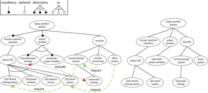
andalternativefeatures as well as binary excludes andrequirescross-tree dependencies. Our running example is a sample SPL from the automotive domain, a Body Comfort System (BCS) [LOGS11]. Figure 1 depicts the feature model for the BCS SPL (left) and a valid product con-figuration (right) in concrete syntax.
alarm system body comfort
system
human machine interface
automatic power window manual power
window central locking requiresystem power
window
automatic locking
remote control key status LED
security
exclude
LED central locking system
LED power window
LED alarm system LED exterior
mirror
require require require
alarm system body comfort
system
human machine interface
automatic
power window central locking requiresystem power window
automatic locking status LED
security
LED central locking system
LED alarm system
mandatory optional alternative or
Figure 1: A feature model and a valid product configuration in concrete syntax.
Abody comfort systemconsists of the mandatory featureshuman machine interfaceandpower windowand an optional featuresecurity. The feature model also defines cross-tree dependencies, e.g, theremote control keyfeature requires acentral locking systemand amanual power window
excludes theautomatic lockingfeature. A feature model can be transformed to a set of conditions in propositional logic over the features [CW07]. A valid product configuration is a set of features that fulfills all conditions, or, in terms of the concrete syntax used in Fig. 1, a valid subtree that satisfies all cross-tree dependencies.
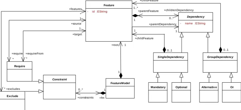
As our graph transformation language Story Driven Modelling(SDM) [F+00] operates on typed graphs (models) inabstract syntax, we need to represent feature models as graphs typed according to a type graph (metamodel). In the following and in the rest of the paper, we shall use the terms modelandmetamodelinstead of typed graphandtype graph, respectively. Our tool
eMoflon1supports Ecore/EMF [ALPS11] and Fig. 2 depicts ourmetamodelfor feature models which is of course neither unique nor optimal, but has proven to be suitable for our needs.
Testing every valid product configuration of the BCS SPL individually is already quite chal-lenging as this would involve testing 152 products. For real-world SPLs that are typically larger2, individual product configuration testing is no longer feasible. The solution provided by the MoSo-PoLiTe framework is to determine a representative subset of valid product configurations
PCU T ⊆FM(F)3according to a combinatorial criterion onFM(F)[OMR10]. For our running
1www.moflon.org
example we could, for example, require thatPCU T comprise all valid pairwise combinations
of features. For a small subset of the BCS feature model consisting of the three features secu-rity, central locking system and remote control key, all valid pairwise combinations would be: (security, central locking system), (security,¬central locking system), (¬security,¬central lock-ing system), (security, remote control key), (security,¬remote control key), (¬security,¬remote control key), (central locking system, remote control key), (central locking system,¬remote con-trol key) and (¬central locking system, ¬remote control key), where ¬f means the feature f is not part of the product. All invalid pairwise combinations would be: (¬security, central locking system), (¬security, remote control key) and (¬central locking system, remote control key). Ecore Diagram FeatureModelLanguage
Constraint
Exclude Require
Mandatory Optional Feature
- id :EString
SingleDependency GroupDependency
Or Alternativ e Dependency
- name :EString
FeatureModel
+target 1
+requireFrom *
+childrenDependency
0..* +parentFeature
1 +features
*
+excludes *
+source 1
+require
*
+parentDependency
1
0..1 +childFeature
1..*
+constraints 0..*
+fm 1
+root 1
1
0..1 +childFeature 1
Figure 2: A metamodel for feature models
Using graph transformations to implement the necessary steps is advantageous as feature mod-els typically have numerous cross-tree dependencies and are, thus, complex graph-like struc-tures. We argue and show with our case-study that graph transformations provide a declarative, high-level means of manipulating such structures and increase not only productivity (via rapid prototyping) but also readability and hence maintainability of the system.
3
MoSo-PoLiTe
security automatic locking body comfort system body comfort system Flattening Transformation alarm system central locking
system control keyremote alarm system require central locking system automatic locking remote control key security security automatic locking body comfort system alarm system central locking system remote control key Optimization Solver List of Pairs Product Configurations Metamodel for feature model
conforms to conforms to conforms to BCS feature model (subsystem)
Flattened feature model (CSP)
Flattened feature model with redundant constraints (CSP)
central lock. system security remote
control key security automatic locking alarm system remote control key security security security remote control key automatic locking central lock. system automatic locking alarm system central lock. system security in-place model transformation (SDM) for flattening in-place model transformation (SDM) for optimization
1
2
1
2
Constraints C2 R1 R2 C13
Ecore Diagram FeatureModelLanguageConstraint
Exclude Require
Mandatory Optional Feature
- id :EString
SingleDependency GroupDependency
Or Alternativ e
Dependency
- name :EString
FeatureModel +target 1 +requireFrom * +childrenDependency 0..* +parentFeature 1 +features * +excludes * +source 1 +require * +parentDependency 1 0..1 +childFeature 1..* +constraints 0..* +fm 1 +root 1 1 0..1 +childFeature 1
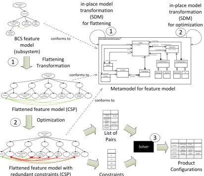
Figure 3: The MoSo-PoLiTe Framework
(1) Flattening Transformation: The BCS feature model is transformed in a first step to a Constraint Satisfaction Problem (CSP= (P,V,C)), which consists of a set Pof parameters, a set V of values, and a set C of constraints. Constraints c∈C are of the form < p,R> where p= (p1,p2, . . . ,pn)is an n-tuple of parameters andRis an n-ary relation onV. A valid
product configurationPCis defined by a mappingv:P→V that fulfills all constraints (i.e., for
c=<(p1,p2, . . . ,pn),R>,(v(p1),v(p2), . . . ,v(pn))∈Rholds).
As SDMs workin-place4, they are especially suitable for endogenous5model transformations and we exploit this by interpreting a flattened form of the feature model as a CSP. Via a series of transformations rules, a feature model can be flattened (Fig. 3::16) until it consists of a root and two layers: the first layer represents the parameters of the CSP, while the leaves are the possible
values of the corresponding parameters. The constraints of the CSP correspond to the cross-tree dependencies of the flattened feature model. Resulting parameters and values are shown for a small subset of the BCS feature model in Figure 4.
security body comfort
system
body comfort system
¬security p_security
Flattening Transformation
central locking system
remote control key p_central
locking system
¬central locking system
p_remote control key
¬remote control key
require
central locking system
remote control key security
BCS feature model (subsystem) Flattened feature model (CSP)
Parameter Layer
Value Layer Cross-Tree Dependencies
Figure 4: Parameter and Value Layer for a BCS-Subset
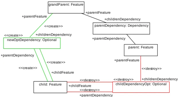
Figure 5 depicts an excerpt of one of the 16 rules used for flattening. In the SDM notation, the left-hand side and right-hand side of a transformation ruler= (L,R)are merged together in a single specification. When the rule is applied to a match in a model, the elements inR\Land
L\Rare created (denoted by the stereotypecreate) and deleted (destroy), respectively. All other elements (L∩R) are retained and do not have a stereotype7. SDMs also have an imperative part for specifying basic control flow, i.e., the order in which rules should be applied. This is however synonymous to an action language with the usual imperative concepts (if/else, forEach) and we shall focus more on the declarative model transformation rules.
ESDM Diagram rule child-optional
parentDependency: Dependency
parent: Feature <<create>>
newOptDependency: Optional
grandParent: Feature
<<destroy>>
childDependencyOpt: Optional child: Feature
+childrenDependency +parentFeature
+parentDependency +childrenDependency
<<create>> +parentFeature
<<create>>
+childFeature <<create>> +parentDependency
+childrenDependency <<destroy>> +parentFeature
<<destroy>> +childFeature
<<destroy>> +parentDependency
Figure 5: A transformation rule used for flattening the feature model.
In our opinion, the SDM specification consisting of flattening rules such as Fig. 5 is quite clear and concise, and is ideal for implementing the required transformation. The rule depicted in Fig. 5 matches a featureparentthat has an optional child-featurechildand flattens this part of the feature tree by deleting theparent-childconnection andpulling upchildby creating an optional dependency tograndParent, the parent feature ofparent.
We refer to [Ost11] for a complete list of rules and the proof that the flattening transformation is indeed semantic preserving (i.e., the equivalent of the feature model in first order logic is retained).
(2) Optimization: In an optimization step (Fig. 3::2), the flattened feature model can be
annotated with extra information to improve the performance of the CSP solver. In our case, optimization rules also implemented with SDMs (discussed in detail in Sec. 4) basically add redundant constraints to the CSP that help the solver to avoid getting caught in a deadlock (partial configuration that cannot be completed to become a valid configuration) and having to backtrack. (3) Solver:In a final step, the optimized CSP issolved, i.e., product configurations that fulfill all constraints are determined until all valid pairwise combinations of features have been covered. For the scope of this paper, the solver is treated as a well-tested black-box that should not be changed (Fig. 3::3).
The CSP solver applies the following strategy: (i) a list of all pairwise combinations of fea-tures are derived from the flattened feature model, (ii) an initial pair is chosen according to a greedy component8 and the solver attempts to extend it to a product configuration that fulfills all constraints in the CSP, backtracking if necessary. If this fails then the initial pair was invalid and is removed from the list of pairs to be covered. If this was successful, all other pairs that are contained in the determined product configuration are marked as covered, (iii) this is repeated until all pairs are covered.
The basic backtracking approach in step (ii) is complemented with aforward check9that re-duces the search space whenever a new parameter value is chosen by removing all parameter values that contradict the current choice. As we shall present in the following section, this al-ready quite effective forward checking technique can be further augmented by adding redundant constraints (cross-tree dependencies) to the CSP.
4
Optimization Strategies
The basic idea of our optimization strategies is to annotate the flattened feature tree (the CSP) by adding redundant constraints. The goal of this optimization is to (1) help filter out pairs of features that are invalid, and (2) further improve the forward check of the solver so that wrong decisions and consequent backtracking can be avoided. The following subsections present three optimization strategies, implemented as graph transformations, with short proofs that the seman-tic preservation of the entire flattening transformation is retained:
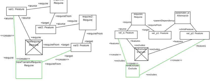
(1) Transitive Closure for Requirements:The first and most intuitive rule involves building the transitive closure of all requirement constraints. As depicted in Fig. 6, a chain of two require-ments induces a direct transitive requirement, which is created if it doesn’t exist already. These
8Based on weights determined by the frequency of pairs.
redundant requirement constraints simplify other rules, which can now assume the transitive clo-sure, i.e.,∀val1,val2,val3 :(val1 requiresval2)∧(val2 requiresval3)⇒(val1 requiresval3).
To show semantic preservation, the corresponding subtree with the extra transitive requirement can be transformed into a set of expressions in first-order logic, which can be reformulated until it is equivalent to the set of expressions of the subtreewithout the extra requirement. This is trivial for transitive require constraints.
(2) Derived Excludes: The second optimization rule concerns deriving extra exclude con-straints. As depicted in Fig. 7, if a certain valuevalqof a parameterqrequires a valuevalp1of a further parameter p, an exclude constraint betweenvalq and another valuevalp2 of pcan be derived if p6=q∧valq=6 valp16=valp2and the exclude constraint does not already exist, i.e. the parameterpcan only be assigned one of its possible values, andvalqrestrains the choice tovalp1 excluding all other options forp.
Please note that our transformation engine implicitly enforcesinjectivematches, i.e., no two object variables in the pattern can be mapped to the same model element. This means we do not have to explicitly demandp6=q∧valq=6 valp16=valp2in the pattern. Also note how NACs (Negative Application Conditions) are depicted asnegativeelements that are cancelled such as
noRequirein Fig. 6 andnoExcludein Fig. 7. ESDM Diagram rule1 Story Diagram
val1: Feature
val2: Feature
val3: Feature require1:
Require
require2: Require
noRequire: Require
<<create>> newTransitivRequire:
Require
+requireFrom
+target +require +source +requireFrom
+target
+require <<create>> +source
+require +source
+requireFrom +target +require
+source
+requireFrom <<create>>
+target
Figure 6: Transitive requires
ESDM Diagram rule3 Story Diagram
requires: Require
val_q: Feature
noExclude: Exclude
val_p2: Feature val_p1: Feature
paramater_p: Alternative
<<create>> newExclude:
Exclude
+excludes
<<create>>
+features
+excludes <<create>> +features
+requireFrom +target +require
+source
+excludes +features
+excludes
+features +childFeature +parentDependency
Figure 7: Derived excludes
As in the case of building the transitive closure for requirements, deriving excludes according to Fig. 7 is also semantic preserving (⊕represents an exclusive or):
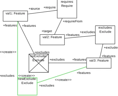
(3) Propagated Excludes: A further rule depicted in Fig. 8 also adds redundant excludes. If a value val1 requires another valueval2 which excludes a further value val3, then val1 also excludesval3. This rule is also semantic preserving as shown in the following:
(val1 requires val2)∧(val2 excludes val3)∧(val1 excludes val3) (7)
⇔(¬val1∨val2)∧(¬val2∨ ¬val3)∧(¬val1∨ ¬val3) (8)
⇔(¬val1∧ ¬val2)∨(¬val1∧ ¬val3)∨(val2∧ ¬val3) (9) ⇔(¬val1∨val2)∧(¬val2∨ ¬val3) (10) ⇔(val1 requires val2)∧(val2 excludes val3) (11)
After deriving the initial CSP via the flattening transformation, the rules (1), (2) and (3) are ap-plied repeatedly in sequence until the total number of constraints of the CSP no longer increases.
ESDM Diagram rule2 Story Diagram
val1: Feature
val2: Feature
val3: Feature requires:
Require
excludes: Exclude
noExclude: Exclude
<<create>> newExclude:
Exclude +excludes <<create>>
+features
+excludes <<create>>
+features +excludes +features +excludes
+features
+excludes
+features +excludes
+features +requireFrom
+target +require +source
Figure 8: Transformation for propagating exclude constraints.
5
Evaluation
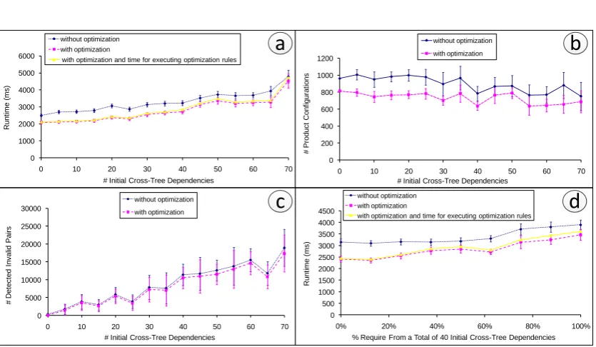
To evaluate our optimization, a series of measurements were performed on a standard PC with a 2.93 GHz Intel Core2 Duo CPU and 4 GB RAM. The underlying operating system and virtual machine was Windows XP Professional SP3 and Java 1.7, respectively, and the amount of time the CPU spent performing actions for the tests, i.e., user time, was measured. For all tests, a feature model generator was implemented that can generate random feature models of a specified size and with a given number of cross-tree dependencies. Figure 9 presents our results10 in 4 plots, which are explained in detail in the following.
Each test was repeated 10 times and measurements were averaged to compensate for fluctu-ations and improve accuracy. Furthermore, 10 different sets of randomly generated cross-tree
0 500 1000 1500 2000 2500 3000 3500 4000 4500
0% 20% 40% 60% 80% 100%
R u n ti me (ms)
% Require From a Total of 40 Initial Cross-Tree Dependencies without optimization
with optimization
with optimization and time for executing optimization rules 0 1000 2000 3000 4000 5000 6000
0 10 20 30 40 50 60 70
R u n ti me (ms)
# Initial Cross-Tree Dependencies without optimization
with optimization
with optimization and time for executing optimization rules
0 200 400 600 800 1000 1200
0 10 20 30 40 50 60 70
# Pro d u ct C o n fi g u ra ti o n s
# Initial Cross-Tree Dependencies without optimization with optimization 0 5000 10000 15000 20000 25000 30000
0 10 20 30 40 50 60 70
# D e te ct e d I n va lid Pa irs
# Initial Cross-Tree Dependencies without optimization
with optimization
d
b
a
c
Figure 9: Effects of optimization strategies.
dependencies were used. All results are depicted with a 95% confidence interval in each data point showing that concrete values may vary, but our results are not dependent on a specific choice of constraints.
Although we were able to verify our results for feature models consisting of up to about 700 features with 10% initial cross-tree dependencies, we chose to use a feature model with 319 features to present our evaluation. This ensures that results can be compared to real feature models available fromwww.splot-research.org, which range in size from about 9 to 290. With feature models consisting of thousands of features our optimization becomes a bottleneck in some cases and an appropriate strategy to restrain the rules as required is left to future work.
Plot (a): The runtime (y-axis) of the whole process is shown for a varying number of initial cross-tree dependencies (x-axis) ranging from 0 to 70. The performance of the process with-out our optimization (blue dotted line) is compared with the performance on the optimized CSP (magenta dashed line) and with the total time (yellow solid line), which includes the time for executing the optimization rules as well. Please note that 0 initial cross-tree dependencies means that the feature model was used withoutinitialcross-tree dependencies. As the flattening trans-formation, however, always introduces extra dependencies to preserve semantics, the resulting CSP, even for 0 initial cross-tree dependencies, still contains a considerable number of con-straints derived from the tree structure of the feature model and from the flattening process. This explains why there is a fairly constant 15% reduction in runtime across the x-axis.
Plot (b): For the same configuration, the sets of generated product configurations are plotted (y-axis) for the same x-axis as in Plot (a). Our optimization clearly leads to a 15–20% reduction of the generated sets. This result is even more important than a reduction in runtime, as this is the actual goal of the whole process.
Plot (c): The reason for the reduction in size of the generated sets of product configurations lies in the improved detection of invalid pairsbeforethe CSP is solved. We obtain best results by filtering as many invalid pairs as possible usingsimpleheuristics, which become more effective with the redundant constraints introduced by the optimization. The number of invalid pairs that couldnotbe filtered and are later detected by the solver is plotted for the same x-axis as in Plot (a) and Plot (b) showing a 10% reduction. Less invalid pairs improves the greedy component11 of the CSP solver as the used weights become more accurate, leading to a reduction in size of the set of product configurations (Plot (b)).
Plot (d): Using the same feature model but with a constant number of 40 initial cross-tree dependencies, runtime (y-axis) is plotted for a varying ratio of requireconstraints to exclude
constraints (x-axis). As two of our three optimization rules involve exclude constraints, the reduction in runtime is higher for a larger number of exclude constraints (0% initial cross-tree require dependencies) and reduces slightly as more exclude are replaced with require constraints (100% initial cross-tree require dependencies). This is confirmed by our measurement results.
6
Related Work
We classify related work into two groups: alternative approaches to SPL testing in general, and approaches that are similar to ours, but differ in how feature models are transformed to a CSP.
Alternative approaches to SPL testing: Approaches to SPL testing can be further cate-gorized into three subgroups: contra-SPL philosophy, reuse techniques, and subset heuristics. Contra-SPL philosophy approaches ignore the inherent reuse in SPLs and are only appropriate for small SPLs [Sch07]. Reuse techniques aim to reduce the testing effort for SPLs by reusing test artifacts (e.g., test cases and data) across products of an SPL. This is achieved by incremen-tally testing products via regression testing techniques or by appropriately adapting domain tests during product testing. Incremental SPL testing, as introduced in [Eng10], faces the challenges of identifying asuitableproduct to start the process with and identifyingwhatneeds to be re-tested. Approaches that adapt domain tests often employ model-based testing techniques for SPLs as models can provide suitable mechanisms to describe variable test-relevant behaviour. We re-fer to [OWES10] for an extensive comparison of model-based testing techniques. Approaches that use subset heuristics aim at generating a representative subset of products according to a coverage criterium such as combinatorial testing [OMR10,POS+11], or requirements coverage [Sch07]. Although SAT solvers can also be used to solve the basic problem of identifying a subset of products that satisfies a set of combinatorial constraints on features [POS+11], feature models mainly employbinaryconstraints over parameters withnon-binarydomains for which CSP solvers seem to be a natural choice [Ben04]. We have furthermore compared our concrete implementation with a SAT approach and our solution proved to be superior in terms of efficiency and the size of determined subsets [POS+11].
Alternative feature model to CSP transformation: The authors of [WDS09] perform a cartesian flattening to transform feature models into aknappsackproblem which is solved and used to generate representative subsets of products of the SPL. A major difference to our flatten-ing approach is that they choose to prohibit an exponential explosion of all possible feature com-binations via the transformation but lose semantic equivalence in the process. As an example, cardinality/or groups are translated into XOR/alternative groups of abounded size [WDS09]. We prefer to retain semantic equivalence between the original and the flattened feature model and control the number of combinations via a coverage criterium that can range from pairwise to n-wise as required. The flattening transformation is, in general, not unique and we also differ from [WDS09] in the treatment ofalternativegroups beneath an alternativeparent as depicted in Fig. 10 for an abstract example taken from [WDS09].
K
N O
L
G G
K L N O ¬L
G
K LN LO
Cartesian Flattening MoSo-PoLiTe Flattening
Figure 10: Flattening approaches for analternativeparent withalternativechildren [POS+11]
In the cartesian flattening approach, the featuresNandOare merged with its parent featureL. If, however, another featureXrequiresL, this binary constraint must be translated intoXrequires (L,N xorL,O) which is a non-binaryconstraint. For this reason we use a different flattening strategy as depicted in Fig. 10 that results in only binary constraints, which are handled better by our subset extraction algorithm.
7
Conclusion
In this paper we presented a novel case study for graph transformations in the domain of SPL test-ing. We have successfully employed SDMs not only for the involved flattening transformation that transforms a feature model into a CSP, but also for an optimization process that adds redun-dant constraints to improve the performance of our unchanged CSP solver. Our results show that the optimization leads to a reduction in runtime and to an increase in quality (reduction in size) of the generated sets of product configurations for pairwise testing. This novel case study for the graph transformation community showcases the advantages of using graph transformations including improved readability and maintainability of the transformation and optimization rules, and the possibility of rapid prototyping further optimization rules.
Last but not least, we shall continue scalability measurements on larger feature models. The cost of performing the optimization rules increases for large feature models (thousands of fea-tures) and leads to a bottleneck as a very large number of constraints is obtained in some cases. Depending on the number of features, an appropriate handling must be implemented to decide how to restrain the optimization rules.
Bibliography
[ALPS11] A. Anjorin, M. Lauder, S. Patzina, A. Sch¨urr. eMoflon: Leveraging EMF and Professional CASE Tools. In 3. Workshop Methodische Entwicklung von Model-lierungswerkzeugen (MEMWe2011). LNI. GI, Bonn, 2011.
[Ben04] H. Bennaceur. A Comparison between SAT and CSP Techniques. Constraints
9(2):123–138, 2004.
[CHE05] K. Czarnecki, S. Helsen, U. Eisenecker. Staged Configuration Through Specializa-tion and Multilevel ConfiguraSpecializa-tion of Feature Models. Software Process: Improve-ment and Practice10(2):143–169, 2005.
[CN01] P. Clements, L. Northrop.Software product lines: practices and patterns. Addison-Wesley Longman Publishing Co., Inc., Boston, MA, USA, 2001.
[CW07] K. Czarnecki, A. Wasowski. Feature Diagrams and Logics: There and Back Again. InProc. of the 11th Int. Conf. on Software Product Lines. Pp. 23–34. IEEE Computer Society, 2007.
[Eng10] E. Engstr¨om. Regression Test Selection and Product Line System Testing. InProc. of the Third Int. Conf. on Software Testing, Verification and Validation. Pp. 512–515. IEEE Computer Society, Washington, DC, USA, 2010.
[F+00] T. Fischer et al. Story Diagrams: A New Graph Rewrite Language Based on the Unified Modeling Language and Java. InTAGT ’98 Selected Papers. LNCS 1764, pp. 296–309. Springer, 2000.
[KBK11] C. H. P. Kim, D. S. Batory, S. Khurshid. Reducing Combinatorics in Testing Product Lines. In Proc. of the 10th Int. Conf. on Aspect-Oriented Software Development. Pp. 57–68. ACM, 2011.
[KCH+90] K. C. Kang, S. G. Cohen, J. A. Hess, W. E. Novak, A. S. Peterson. Feature-Oriented Domain Analysis (FODA) Feasibility Study. Technical report, Carnegie-Mellon University Software Engineering Institute, 1990.
[McG01] J. D. McGregor. Testing a Software Product Line. Technical report CMU/SEI-2001-TR-022, 2001.
[OMR10] S. Oster, F. Markert, P. Ritter. Automated Incremental Pairwise Testing of Software Product Lines. InProc. of the 14th Int. Software Product Line Conf.Pp. 196–210. 2010.
[Ost11] S. Oster. A Semantic Preserving Feature Model to CSP Transformation. Technical report 11, Technische Universit¨at Braunschweig, 2011.
[OWES10] S. Oster, A. W¨ubbeke, G. Engels, A. Sch¨urr. Model-Based Software Product Lines Testing Survey. In Zander et al. (eds.),Model-based Testing for Embedded Systems. CRC Press/Taylor&Francis, 2010. to appear.
[OZML11] S. Oster, I. Zorcic, F. Markert, M. Lochau. MoSo-PoLiTe - Tool Support for Pair-wise and Model-Based Software Product Line Testing. In Czarnecki and Eisenecker (eds.), 5th Int. Workshop on Variability Modelling of Software-Intensive Systems. Pp. 79–82. ACM Press, New York, 2011.
[PBL05] K. Pohl, G. B¨ockle, F. J. v. d. Linden.Software Product Line Engineering: Founda-tions, Principles and Techniques. Springer-Verlag New York, Inc., USA, 2005.
[POS+11] G. Perrouin, S. Oster, S. Sen, J. Klein, B. Baudry, Y. Traon. Pairwise Testing for Software Product Lines: Comparison of Two Approaches.SQJ - Special issue on Quality Engineering for SPLs, 2011.
[Sch07] K. Scheidemann. Verifying Families of System Configurations. PhD Thesis, TU Munich 2007.
[WDS09] J. White, B. Dougherty, D. C. Schmidt. Selecting Highly Optimal Architectural Feature Sets with Filtered Cartesian Flattening. Journal of Systems and Software
![Figure 10: Flattening approaches for an alternative parent with alternative children [POS+11]](https://thumb-us.123doks.com/thumbv2/123dok_us/7805810.2085046/13.595.166.427.308.365/figure-flattening-approaches-alternative-parent-alternative-children-pos.webp)
