International Journal of Research in Engineering & Applied Sciences 51 http://www.euroasiapub.org
DISTANCE CONTROL OF HOME ELECTRIC APPLICATIONS USING
GSM MODULE AND AT 89C2051 MICROCONTROLLER
Veerepalli Vidyadhar* Vishal Battula** Ramesh Padarla***
ABSTRACT
In this paper we describe the Distance control of Home Electric applications using GSM Module
and AT 89C2051 microcontroller.This module can be extended to the any number of Electric
applications by having an interface chip to 89C2051 microcontroller. Sending SMS through
GSM modem when interfaced with microcontroller or PC is much simpler as compared with
sending SMS through Modem in PDU Mode. Text message may be sent through the modem by
interfacing only three signals of the serial interface of modem with microcontroller i.e., TxD,
RxD and GND. When GSM module receives the message it sends the message in bit by bit form
to the micro controller using UART. Now this micro controller sends signal to the ULN2003
Driver chip. Driver chip basically acts on open drain principle.To realize mobile control,
89C521 Microcontroller, electromagnetic relays, Driver circuit (ULM 2003) and GSM
technologies for power management have been examined in this paper..
Key words: Distance Control, Home Electric applications, GSM Module, Short Message Service,
Micro controller,AT 89C2051.
*Department of Electrical Engineering, Indian Institute of Technology, Roorkee, Roorkee, Uttarakhand, India
**Department of Electrical Engineering, Indian Institute of Technology, Roorkee, Roorkee, Uttarakhand, India
International Journal of Research in Engineering & Applied Sciences 52 http://www.euroasiapub.org
I .INTRODUCTION
The Global System for Mobile Communication (GSM) has become a very popular mode of communication. With mobile revolution in many third world countries like India opened up huge volume of working space for developing applications based on Mobile Services.
Distance control of Home Electric applications using GSM Module and AT 89C2051 microcontroller is one such application. Furthermore, to remotely control home appliances, the system to be developed would consists of a mobile phone and a microcontroller, which is characterized by input, and output terminals that can be utilized as communication channel to send message between the microcontroller and the devices being controlled. . As a result, GSM phone can be used in household power management to turn ON or OFF devices via a command in a Short Message Service (SMS) sending to the mobile phone connected to the automated device’s controller.
The message is a data made up of address and command from microcontroller to the device being controlled. Conclusively, this paper is aimed at developing a GSM based Distance control of Home Electric applications could be used to remotely control for any number of electric applications using an interface chip.
II. BASIC CIRCUIT AND DESIGN
We designed a relay circuit using 89c51 microcontroller which could be switched on by single SMS to the device and can also be switched off by another SMS. Designed for control, this project provides 4 relay outputs. It can be used in various applications including load contact closure. The project presented here is based on world’s most powerful Intel’s mcs-51 family of microcontroller Atmel at89c51.In this project we are using AT 89C2051 microcontroller, because this controller has two ports which are more than enough for our project
GSM modem is being interfaced with the microcontroller AT89s51 for SMS communication. The SMS can be sending for the control of devices. There are many applications of the project based on microcontroller 8051 and GSM interfacing. We can use it as a remote control of industrial machines or we can sue it for home automation or we can use it for the security of home or offices.
International Journal of Research in Engineering & Applied Sciences 53 http://www.euroasiapub.org
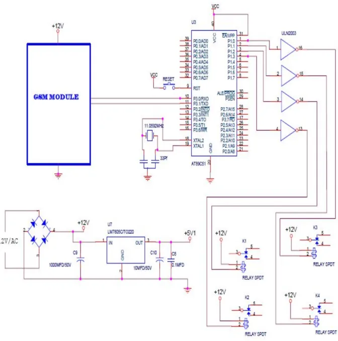
sent through the modem by interfacing only three signals of the serial interface of modem with microcontroller i.e., TxD, RxD and GND. In this scheme RTS and CTS signals of serial port interface of GSM Modem are connected with each other. The transmit signal of serial port of microcontroller is connected with transmit signal (TxD) of the serial interface of GSM Modem while receive signal of microcontroller serial port is connected with receive signal (RxD) of serial interface of GSM Modem as shown in the Figure.1.
International Journal of Research in Engineering & Applied Sciences 54 http://www.euroasiapub.org
III. CIRCUIT IMPLEMENTATION
The Power supply is taken through a step down transformer to decrease the voltage. This transformer gives 12V AC output. Diodes d1 to d4 are power rectifier diodes connected in bridge circuit c in circuit depicts the filter capacitor. Input to the bridge rectifier is transformer output which is12V AC. Output of the bridge rectifier and capacitor is 12V DC. All our relays are operated by 12V DC. Relay output can be connected to any 250V 7 ampere load. We should not cross this limit otherwise it will damage the relay circuit. 7805 regulator gets its input from the 12V DC power.5V DC is available at pin no 3 of this IC.c2 and c3 are filter capacitors ld1 is a power indication led IC2 is Atmel AT89c51 microcontroller. It has two ports port1 and port 3. This controller has inbuilt UART (Universal Synchronous, Asynchronous Receiver Transmitter), and pin no 10 is Rx pin and pin number 11 is Tx pin of the UART. Through these two pins microcontroller is able to communicate with the GSM sim module through UART.
UART is described as Universal Asynchronous Receiver/Transmitter. This is a type of "asynchronous receiver/transmitter", a piece of computer hardware that translates data between parallel and serial forms. UARTs are commonly used in conjunction with communication standards such as EIA, RS-232, RS-422 or RS-485. The universal designation indicates that the data format and transmission speeds are configurable and that the actual electric signaling levels and methods (such as differential signaling etc.) typically are handled by a special driver circuit external to the UART.
A UART is usually an individual (or part of an) integrated circuit used for serial communications over a computer or peripheral device serial port. UARTs are now commonly included in microcontrollers. A dual UART or conversion between serial and parallel forms. Serial transmission of digital information (bits) through a single wire or other medium is much more cost effective than parallel transmission through multiple wires.
International Journal of Research in Engineering & Applied Sciences 55 http://www.euroasiapub.org
The working of the whole project is described below:
We have to send message to the Sim in GSM module in forms of 1’s and 0’s, this is nothing but we are sending the message in form of binary digits. Each bit represents each device connected through the circuit. For example if we send 1101 as message then the hard ware will switch on the 1st, 2nd, and 4th devices and turns off the 3rd device. Like this we can control the whole set up by sending 1’s and 0’s which means on and off respectively
The micro controller runs as per the program installed in it. This program is written in C language and compiled using keil compiler. Now this program is installed in the microcontroller using u programmer.
When GSM module receives the message it sends the message in bit by bit form to the micro controller using UART Now this micro controller sends signal to the ULN2003 Driver chip. Driver chip basically acts on open drain principle.
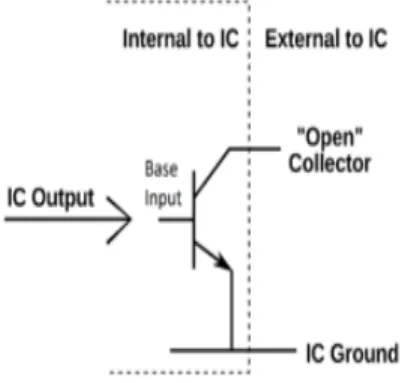
An open collector is a common type of output found on many integrated circuits (IC). Instead of outputting a signal of a specific voltage or current, the output signal is applied to the base of an internal NPN transistor whose collector is externalized (open) on a pin of the IC. The emitter of the transistor is connected internally to the ground pin. If the output device is a MOSFET the output is called open drain and it functions in a similar way.
DUART combines two UARTs into a single chip. Many modern ICs now come with a UART that can also communicate synchronously; these devices are called USARTs (universal synchronous/asynchronous receiver/transmitter).
The Universal Asynchronous Receiver/Transmitter (UART) takes bytes of data and transmits the individual bits in a sequential fashion. At the destination, a second UART re-assembles the bits into complete bytes.
In figure 2, the transistor base is labeled "IC Output". This is an internal output from the internal IC logic to the transistor. From the point of view of the transistor, this is the input which controls the transistor switching. The external output is the transistor collector, and the transistor acts as an interface between the internal IC logic and parts external to the IC.
International Journal of Research in Engineering & Applied Sciences 56 http://www.euroasiapub.org
is turned off. When the transistor connected to this resistor is turned on, the output is forced to nearly 0 volts.
Fig. 2. Open Drain System
The output is fed to SPDT Relay. There are 3 poles for this pcb spdt relay, two are for forming the control circuit and the remaining one acts as a switch by making and losing the contact with the circuit. The two terminals of the controlling circuit are connected with the driver chip output and 12V supply. Phase voltage is connected to the lamp circuit through the relays, so now when the relay makes contact the bulbs glow and when it loses the contact it gets off. Driver chip operates such that the output is at 0V i.e.., grounded state or in open state. Hence when it gives 0V the circuit is completed and the relay operates, the bulbs glow. If it gives the output as open circuit then the bulb goes off. In this way the hardware device controls the supply.
V. SOFTWARE IMPLEMENTATION
International Journal of Research in Engineering & Applied Sciences 57 http://www.euroasiapub.org
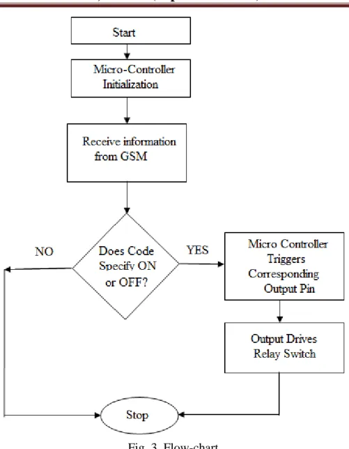
Fig. 3. Flow-chart
VI. RESULTS
Sample Case at home with four electric applications:
Average time during which Electrical appliances are left running: 5 hrs per day Average power consumption during the above time:
Average power consumed by Tube light: (40 watts /0.9 + 40) = 85 Watts per hour Average Power consumed by Fan: 50 watts per hour
Average Power consumed by laptop: 100 Watts per hour
Average power consumed by Geyser: 3000/10=300 watts per hour
International Journal of Research in Engineering & Applied Sciences 58 http://www.euroasiapub.org
=2675 watts or 2.675 KWh or 2.675 units of electricity
Money spent on purchasing this power = 5.3*2.675 = Rs 14.1775/- Cost of installation = Rs 6500/-
Payback time (Time during which the installation costs are recovered) = 6500/14.1775 = 458.472 days or 1.25 years
VII. CONCLUSIONS
In this project a mobile-controllable power outlet system and the key components for home power management have been developed. To realize mobile control, 89C521 Microcontroller, electromagnetic relays, Driver circuit (ULM 2003) and GSM technologies for power
management have been integrated. The proposed MPCOM is designed for wireless controlling of different electric home appliances connected over a GSM network in a domestic environment. The MPCOM also a GSM cellular mobile phone using SMS and PC or Notebook using the Internet control electric home appliances at remote locations. The experiments and the analysis reported in this project have demonstrated that this new system can be practically implemented and provides adequate results. While this study has its limitations, it is hoped that it will serve as a basis for further study of home power management strategies for various electric home
appliances.
Home power management is required to save energy and reduce carbon dioxide emissions. With burgeoning prices and depleting resources effective power management and home automation provide a good alternative. The device can be scaled to integrate various other technologies like Bluetooth, Infrared, RF technologies to achieve similar results. Miniaturization of the entire hardware kit and its development and cost-effective production is imperative to encourage the idea of home automation in the Indian power sector. Minimization and optimal power consumption by the device is also a challenge that needs to be addressed in the future versions of this device.
VIII. REFERENCES
International Journal of Research in Engineering & Applied Sciences 59 http://www.euroasiapub.org
[2] D.S. Kim, J.M. Lee, W.H. Kwon, and I.K. Yuh, “Design and implementation of home network systems using UPnP middleware for networked appliances,” IEEE Transaction Consumer Electrons, vol. 48, issue 4, pp. 963-972, Nov. 2002.
[3] Masahiro Inoue, Toshiyasu Higuma, Yoshiaki Ito,Noriyuki Kushiro, and Hitoshi Kubota, “Network Architecture for Home Energy Management System,” IEEE Transaction on Consumer Electronics, vol. 49, no. 3, pp. 606-613, Aug. 2003.