364
Copyright © 2011-15. Vandana Publications. All Rights Reserved.
Volume-5, Issue-3, June-2015
International Journal of Engineering and Management Research
Page Number: 364-369
Stress and Deformation Analysis of Accelerated Pedal Mechanism
Vedaprabha H C1, Mohammed Mohsin Ali H.2
1
4th Sem, M. Tech (MSE), Department of Mechanical Engineering, Ghousia College of Engineering, Ramanagara-Karnataka,
INDIA
2Associate Professor, Department of Mechanical Engineering, Ghousia College of Engineering, Ramanagara-Karnataka, INDIA
ABSTRACT
Accelerator pedal is used to modulate the engine power supply. It is normally paired with brake pedal or sometimes paired with clutch which helps the driver to control the speed excessively. The accelerator pedal consists of three main parts they are pedal plate, pedal arm and pivot shaft. The purpose of the present work is to determine the stress and deformation under different loading conditions using Finite element analysis package called ANSYS. The accelerator pedal design is carried out using CATIA and later
it is imported into Hyper mesh to discretize the pedal by using solid 185 element. Discretized elements are later imported into ANSYS and two boundary conditions were applied that is load of 400N and 450N and constrained boundary condition.
Keywords---- ANSYS, Accelerator pedal, CATIA
I.
INTRODUCTION
An types of vehicles, that allows an operator to modulate engine power remotely. It is generally paired with a brake pedal, and sometimes a clutch, enabling a driver to control the speed of the vehicle almost exclusively with his feet. An accelerator pedal is typically connected to a directly, either by cables or, electronically, to a computer that mechanically adjusts the throttle based on pedal input. Figure 1 shows the structure of the accelerated pedal.
Accelerator pedal designs are almost always developed so that the pedal itself can be pushed down to the floor with the user's toe or upper portion of the foot, while the heel remains on the floor. This allows a much greater degree of control, as the ankle joint can modulate pressure rather than the hip joint, which would effectively be the case if the entire foot rested on the pedal. Designs are also usually much narrower compared to brake pedals, with the idea that the brake should be easier to find in case of an emergency.
In recent years, composite materials have been used in interior automotive components because of their properties
such as low weight, high specific stiffness, corrosion free, ability to produce complex shapes, high specific strength and high impact energy absorption etc. Therefore, this work is towards the development of an interior automotive component such as composite accelerator pedal for replacing it with the existing metallic one to reduce weight in conformation with safety standards.
Most of the automotive accelerator pedals generally fail due to inappropriate decisions during selection of design concept, material and manufacturing process. In this work, Concurrent Engineering (CE) approach has been used to determine the most optimum decision on design concept and material of the composite accelerator pedal at conceptual design stage.
This work relates to pedal mechanism for motor vehicles, an object of the work being to provide an improved construction of pedal which facilitates the driving of an automobile, reducing to a minimum the fatigue of driving, and giving greater comfort, ease and safety than has been possible heretofore.
365
Copyright © 2011-15. Vandana Publications. All Rights Reserved.
The material considered for the rod and gear wheel is structural steel.
II.
METHODOLOGY
The figure 2 shows the step by procedure for the analysis of accelerated pedal mechanism. In the flowchart it explained about detail plan for the proposed work by clearly specifying the process using different symbols.
Figure 2 Flowchart of the method
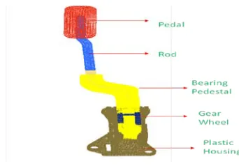
COMPONENT DECRIPTION: Accelerator pedal consists of five main parts namely pedal, rod, bearing pedestal, gear wheel, plastic housing. Figure 3 shows the components of accelerated pedal.
Figure 3 Components of accelerated pedal
The pedal is made from Structural Steel. It is available as a floor mounted or suspended pedal. The function of the accelerator pedal is to give a direct sensation coupling the rod of pedal is made from Structural Steel. Bearing pedestal is an independent support for a bearing, usually incorporating a bearing housing and is made from plastic material. A gear wheel is a toothed wheel that engages another toothed mechanism in order to change the speed or direction of transmitted motion and is made from structural steel. Housings made of plastics that provide superior resistance to corrosion as compared to standard series cast iron units. This series is especially useful in a wide variety of applications because of the nonmagnetic and rust free properties of the housing. Table 1 shows the components and materials used for the components of accelerated pedal.
Table 1 components and materials of pedal
MATERIAL SELECTION: Material selection process is carried out by Selection of matrix and reinforcement composite materials. Figure 2 shows FE model of accelerated pedal.
366
Copyright © 2011-15. Vandana Publications. All Rights Reserved.
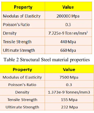
The FE model consists of solid 17474 elements were used for the body and pedal structures. The cover plate was modeled using three-node plate elements. The choice of these three-node elements was required to facilitate the match up of grid patterns between the body and cover where gap and rigid elements were connected. Although three-node plate elements are exceeding stiff, a very high mesh density was used to correct for this deficiency. The cover was modeled as 2.54 mm thick. A very simple constraint set is used in this analysis. The pin attachment bolt (upper part of the body) is fixed to simulate its contact with the base. At the lower sliding connection, a small chunk of plastic is used to enforce contact (gap elements on all sides) between the body and base. Table 2 and table 3 shows the material properties of Structural Steel material and Plastic material.
Table 2 Structural Steel material properties
Table 3 plastic material properties
LOADS AND BOUNDARY CONDITIONS: The
boundary condition is the application of a force and/or constraint. In Hyper Mesh, boundary conditions are stored within what are called load collectors. Load collectors may be created using the right click context menu in the Model Browser. Figure 5 shows the load applied region and assembly constrained areas. Figure 6 shows load conditions. The total load of 400N is distributed on 20Nodes. Load on each node is 20N. Entire assembly is constrained with 6 Degrees of freedom, all these are bolt locations. Figure 7(a) and (b) shows the boundary conditions. Figure 7(a) shows structure of boundary condition and figure 7(b) shows interior assembly.
Figure 5 Load applied region and assembly constrained areas of accelerated pedal
Figure 6 Load conditions of pedal
Figure 7(a) structure of boundary condition
Figure 7(b) interior assembly of boundary condition
III.
PRIOR APPROACH
Starting with the initially engine vehicles, there has dependably been a requirement for the user to conform motor yield so as to control speed. In early designs, the pedal itself was directly tied to either in the carburetor itself or the let more or less in air.
367
Copyright © 2011-15. Vandana Publications. All Rights Reserved.
Other pedals incorporate some type of position sensor that converts the mechanical position into an electrical signal. In the field of automobiles and trucks, a mechanical bracket using a cable, often referred to as a Bowden cable, is the standard method for controlling the throttle of internal combustion engines. These pedal assemblies have a desirable feel and functionality and, with a few refinements, are extremely reliable. This type of pedal assembly defines the mechanical standard today.
IV.
PROPOSED WORK
An accelerator pedal control mechanism provides a position able stop to resist pedal depression beyond a point at which optimum stress and deformation is realized during vehicle acceleration. The position of the stop relative to the accelerator pedal is controlled by an assembly of pedal. The desired point of accelerator depression for a given condition is pedal operating parameters. A caged limit spring is carried on the underside of the accelerator pedal for engagement with the stop, thus allowing the operator to sense the additional resistance of the spring through the accelerator pedal when the appropriate amount of accelerator depression is reached. The spring permits the user to override the modified control by pushing on the quickening agent pedal with adequate power to conquer the farthest point spring. The analysis of the accelerator pedal uses stress analysis to optimize the stress of the pedal. Stress analysis is also used to analyze the material at the point of maximum load on the pedal. The object of the present invention is to influence the operator to follow an optimum mode of operation during vehicle acceleration to attain less stress and deformation. Another object of the invention is to permit the operator to override this influence so as to not suppress the operator's will to overtake and pass other vehicles safely.
V.
RESULTS
The analysis carried out using ANSYS software. The analysis of the accelerator pedal uses stress and deformation analysis to optimize the mass of the pedal. The stress and deformation analysis is also used to analyze the material at the point of maximum load on the pedal. The result of the proposed work is analyzed for two different cases. The case 1 consider the load of 400N and 450N for rod of diameter 10mm.The case 2 consider the load of 400N and 450N for rod of diameter 12mm.The case 1 analyze the result for two different loads 400 N and 450 N of diameter 10mm. The case 2 analyze the result for two different loads 400 N and 450 N of by increasing the pedal rod diameter by 10mm to 12mm
Deformation for 400N and 450N load for pedal: In this the load of 400N has to be applied on pedal. The figure 8 shows the deformation 33.8271mm when the load of 400N has applied. The figure 9 shows the deformation 38.1061mm when the load of 450N has applied. In this case the rod diameter is 10mm. By this it is clearly stating that deformation always increases when the load increases for the same assembly.
Figure 8 Deformation fo load of 400N
Figure 9 Deformation for load of 450N
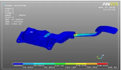
Maximum stress for 400N and 450N load of rod 10mm diameter:In this the stress for the pedal assembly has to be considered. The figure 10 shows the load of 400N has to be applied on the pedal then the maximum stress of 268.46Mpa should be considered at the rod part.
368
Copyright © 2011-15. Vandana Publications. All Rights Reserved.
The figure 11 shows the load of 450N has to be applied on the pedal then the maximum stress of 415.922Mpa should be considered at the rod part. By this it is clearly stating that when load increases for same pedal assebly then stress is also increases.The reserve factor cosidered for that assembly will be treated as poor design safety.
Figure 11 Maximum stress for load of 450N of 10mm diameter
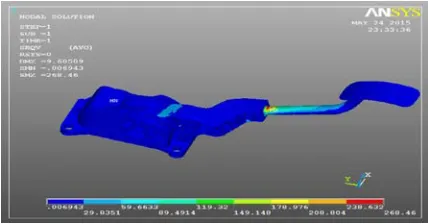
Maximum stress for 400N and 450N load of rod diameter 12mm: The rod diameter has to be increased to improve the reserve factor of the design. The figure 12 shows the maximum stress 238.632Mpa should be considered for the rod part and it is less compare to the rod of diameter 10mm.The figure 13 shows the maximum stress 335.576Mpa for the rod and it is less compare to rod of diameter 10mm.
Figure 12 Maximum stress for load of 400N of 12mm diameter
Figure 13 Maximum stress for load of 450N of 12mm diameter
VI.
CONCLUSION
In this an attempt has been made to design and static analysis of accelerated pedal using ANSYS for the load of 400N and 450N for different rod diameters of 10mm and 12mm. The maximum deformation for the accelerated pedal assembly for 400N load, 10mm diameter is 33.87mm and for 450N load, 10mm diameter is 38.1mm respectively. The maximum deformation for the accelerated pedal assembly for 400N load, 12mm diameter is 15.2mm and for 450N load, 12mm diameter is 17.6mm respectively. The reserve factor for each component is evaluated based on von misses theory of failure. The value of reserve factor for all components is more than 1. As per von misses theory of failure, Design is safe. The maximum von misses stress is observed on rod (at the interface of rod and plastic housing),which is 369.7Mpa for 400N load,10mm diameter and 415.9Mpa for 450N load, 10mm diameter respectively. The maximum von misses stress is observed on rod, which is268.4Mpa for 400N load, 12mm diameter and 335.5Mpa for 450N load, 12mm diameter respectively.
REFERENCES
[1] Aljibori, S.; Hakim, S.: Fiber Reinforced Composites (FRC) structures with potential applications: literature review, International Journal of Applied Engineering Research, 4(10), 2009, 1939-1954
[2] Alemu, M.-B.: Design for manufacturability and concurrent engineering for product development, World Academy of Science, Engineering and Technology, 49, 2009, 240-246.
369
Copyright © 2011-15. Vandana Publications. All Rights Reserved.
Journal of Manufacturing Technology and Management, 6(3/4), 2004.
[5] Denise, C.; Hiroyuki, Y.; Sunao, F.; Christian, L.; Kasserra, P.-H.: Application of nylon composite recycle technology for automotive parts, Proceedings. JSAE Annual Congress 107-02, 2002,1-4
[6] Fuchs, E.-R.-H.; Field, F.-R; Richard, R.; Kirchain; Randolph, E.: Strategic materials selection in the automobile body: economic opportunities for Polymer Composite Design, Journal of Composite Science and technology, 66(9), 2008, 1989-2002
[7] Gulur, S.-S.-S, Sambagam, V.: Mono composite leaf spring for light weight vehicle design, end Joint analysis and testing, Journal of Materials Science, 12(3), 2006, 220-225
[8] Gummadi, S.-A.-J.-K.: Optimum design and analysis of a composite drive Shaft for an automobile, Master’s degree Thesis, Blekinge Institute of Technology Karlskrona, Sweden, 2006.
[9] Murat, O.: The use of composite materials in automotive industry, M.Sc. Thesis, Institute of Natural and Applied Sciences, Cukurova University, Turkey, 2010. [10] McMahon, C.-D.; Scott, M.-L.: Innovative techniques for the finite element analysis and optimization of composite structures, 23rd International Congress of Aeronautical Sciences, Toronto, Canada Page No. 61, 8-13 September, 2002.
[11] Sapuan, S.: A conceptual design of the concurrent engineering design systems for polymazcaeric-based composite automotive pedals, American Journal of Applied Science, 2, 2005, 514-525.