Please cite this article as: M. Norouznejad Jelodar, B. A. Ganji, Design of High Sensitivity and Linearity MEMS Capacitive Tire Pressure Sensor using Stepped Membrane, International Journal of Engineering (IJE), TRANSACTIONS C: Aspects Vol. 29, No. 3, (March 2016) 321-327
International Journal of Engineering
J o u r n a l H o m e p a g e : w w w . i j e . i rDesign of High Sensitivity and Linearity Microelectromechanical Systems Capacitive
Tire Pressure Sensor using Stepped Membrane
M. Norouznejad Jelodar, B. A. Ganji*
Department of Electrical and Computer Engineering, Babol University of Technology, Babol, Iran
P A P E R I N F O
Paper history:
Received 10 December 2015
Received in revised form 02 February 2016 Accepted 03 March 2016
Keywords:
Capacitive Pressure Sensor Sensitivity
Tire Pressure Monitoring System Linearity
A B S T R A C T
This paper is focused on a novel design of stepped diaphragm for MEMS capacitive pressure sensor used in tire pressure monitoring system. The structure of sensor diaphragm plays a key role for determining the sensitivity of the sensor and the non-linearity of the output. First, the structures of two capacitive pressure sensors with clamped square flat diaphragms, with different thicknesses are investigated and their sensitivity and non-linearity are compared together. Finally, for increasing the sensitivity and linearity, a new capacitive pressure sensor with a stepped diaphragm is introduced. A numerical solution for determination of the accurate sensitivity of the sensor is presented. The results show that the sensitivity of the sensor is increased from 0.063 fF/KPa in flat diaphragm to 0.107 fF/KPa in stepped diaphragm and also the non-linearity is decreased from 2.37 to 1.857%. In this design, the sensor sensitivity and output linearity are increased simultaneously.
doi: 10.5829/idosi.ije.2016.29.03c.06
1. INTRODUCTION1
In recent years, significant progress has been carried out on microelectromechanical systems (MEMS), in the meantime, pressure sensors have gained significant place in medical, automotive, industrial and aerospace industries due to various advantages like small size, low weight and compatibility. Automotive industries are the leading consumer of pressure sensors. Typical applications are airbag or tire pressure monitoring systems (TPMS), oil pressure sensing (OPS), engine management system (EMS), vacuum brake booster, transmission fluid pressure [1]. More and more countries are planning to announce the transportation rules that require vehicles installing the TPMS sensors for every wheel. To fulfill the market demand, recently the researches on TPMS sensors have been intensively motivated [2].
Maintaining correct inflation pressure in tires helps to keep vehicle handling and braking at its best, as well as improving fuel efficiency and tire life. In addition, it can prevent such events as tread separations and tire
11*Corresponding Author’s Email: [email protected] (B. A. Ganji)
blowouts which may cause loss of control of a vehicle and severe crashes such as rollovers [3]. A tire can lose up to half of its air pressure without appearing to be underinflated and most people ignore the state of their tires so data shows that nearly 250,000 accidents per year occur in the united states alone due to low tire pressure [4]. Tire pressure monitoring system (TPMS) is one of the biggest automotive safety equipment required for safety on the road. Tire pressure monitoring systems (TPMS) are a way of warning a driver that the tire is incorrectly inflated, which will decrease the safety and performance of the vehicle, and increase the risk of an accident [5]. The TPMS must illuminate a low tire pressure warning telltale not more than 20 minutes after the inflation pressure in one or more of the vehicle’s tires, up to a total of four tires, which is equal to or less than either the pressure 25percent below the vehicle manufacturer’s recommended cold inflation pressure [6].
correctly inflated or not [1]. The MEMS pressure sensors can either be piezoresistive or capacitive. MEMS capacitive sensors provide high pressure sensitivity, low noise, low power consumption and unlike piezoresistive sensors. They have low temperature sensitivity, so they are more suitable for using in tire. The capacitor sensors suffer from the nonlinear output and low capacitance sensitivity [7]. To address these problems one can lessen the air gap and turn the diaphragm to the touch mode [8, 9]. However, in the beginning, when the pressure is low and the diaphragm has not yet turned into the touch mode, the output is nonlinear and has not so much sensitivity. One way to reduce the amount of non-linearity is to increase the diaphragm thickness [5]. It shall be noticed that by more increase in the diaphragm thickness, the sensor sensitivity will considerably decrease. Another way is to increase the middle part of the diaphragm. In this way, the output characteristic will be more linear while the capacitor sensitivity decreases because of increasing the stiffness [10, 11].
In this paper, first capacitive sensor with clamped flat diaphragm is investigated and simulated as a main structure. For achieving more linear output, capacitive sensor with thicker diaphragm is used and to address the sensitivity problem we proposed capacitive pressure sensor with stepped diaphragm. Each sensor has a square diaphragm made of poly silicon material.
2. DESIGN OF MEMS CAPACITIVE PRESSURE SENSOR
The capacitive sensor is made of two parallel plates with air gap. With biasing DC voltage between two plates, they act as electrode of capacitors. The upper electrode is usually moving which can be square, rectangular or circular and the lower one is fixed. In these sensors, the diaphragm moves, so the capacitance between two electrodes is changed and can be measured by an intermediate electronic circuit. The diaphragm's shape influences on deflection of the diaphragm due to the application of an external pressure. Among the variety of diaphragms, rectangular diaphragm has non-uniform stress distributions due to the lack of asymmetry of the structure [12] which resulted in the displacement of less than a square or circular diaphragm with the same areas [13]. With the same width, the effective areas for diaphragms of square and circular shapes are different. Under this condition, with the same pressure load, the square diaphragms have more center deflection than the circular diaphragms [14]. In addition, a square diaphragm can easily and accurately be fabricated because of anisotropic nature of the silicon crystal structure [15]. As a result, it was decided to utilize a square diaphragm instead of a round structure.
The structure of the sensor for clamped diaphragm consists of silicon back plate and poly silicon diaphragm.
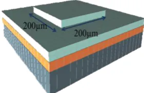
In our design, the thickness of the 0.4 mm 0.4 mm membrane is 5 µm, and the height of the air gap is about 5 µm. Figure 1 illustrates the simulation setup of the capacitive pressure sensor with flat diaphragm. The residual stress for poly silicon is around 20 MPa. The Young’s modulus and Poisson’s ratio of poly silicon are assumed to be Pa and 0.22, respectively. Poly silicon is used as the structural material for the sensor diaphragm because of low stress compared to other materials. High-temperature annealing of a low pressure chemical vapor deposition (LPCVD) of poly silicon thin film which is ion implanted with phosphorous can confine the residual stress as low as 20 MPa [15]. Two steps of improvement have been done to reduce the amount of non-linearity and to increase the capacitor sensitivity of the sensor.
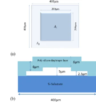
Figure 2 demonstrates the simulation setup of the capacitive pressure sensor with stepped diaphragm using Intellisuite MEMS design tool. The stepped diaphragm could be applied to increase capacitive sensitivity. This structure is proposed with respect to the diaphragm deviation so that near the diaphragm center, the height of the air gap is about 5 µm and near the anchor the gap reduces to 2.5µm.
Figure 1. Simulation setup of capacitive pressure sensor with flat diaphragm
Figure 3. Cross section view of typical pressure sensor with flat diaphragm
3. ANALYSIS OF CAPACITIVE PRESSURE SENSOR
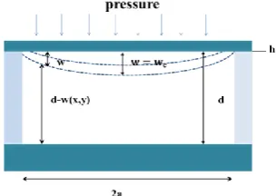
Figure 3 illustrates the cross-section view of the typical pressure sensor with flat diaphragm. The diaphragm side length is 2a, thickness h, the air gap is d and P is an external uniform pressure.
3. 1. Mechanical Sensitivity Analysis The central deflection, , of a flat and circular diaphragm with clamped edges and with initial stress, due to a homogeneous pressure, P, can be calculated from [16]:
(1)
where, R is the radius, h is the thickness, E is young modulus, ν is the poison's ratio of the circular diaphragm, and is residual stress. The deflection of a flat clamped square diaphragm without residual stress is given approximately by [17]:
(2)
where a, is the half-side length of the square diaphragm. For large value of initial tension, the deflection of a flat circular diaphragm can be represented by:
(3)
The theory being valid for circular membranes is converted to the square diaphragms assuming equal
areas , thus by replacing with
in Equation (3), the deflection of a flat square diaphragm can be approximated by [18]:
(4)
This resistance to bending due to initial stress can be added to Equation (2) using the principle of superposition.
(5)
with regard to the relationship between the center deflection and the applied pressure, it can be seen that if this relation is approximately linear. The mechanical sensitivity of a diaphragm is defined as [19]:
(6)
Ignoring the third-order term, for a small deflection (less than 30% of its thickness), the mechanical sensitivity of a flat square diaphragm can be determined by [20]:
(7)
3. 2. Sensor Sensitivity Analysis For square diaphragm, small deflection at any point (x,y) can be determined via the following equation [21]:
(8)
where, a, is the half side-length and D is the flexural rigidity of the plate which is calculated as:
(9)
The maximum deflection will be happen at the center (x=0, y=0) and it is derived as:
(10)
The capacitance for air as a dielectric is defined as [15]:
(11)
Expansion Taylor series can be used for calculating the above integral. Taylor series expansion is given by the following equation:
(12)
Since in this case , therefore formula (12) simplified as follows:
(13)
As long as the sensor works in the small deflection, the capacitance, neglecting the higher order factors, can be calculated by: c w h w R h h w R v h E h w R v h E
p c c 2 c
2 3 4 2 4 4 2 4 4 ) 1 ( 83 . 2 ) 1 ( 33 . 5
3 4 2 4 4 2 4 ) 1 ( 58 . 1 ) 1 ( 2 . 4 h w a v h E h w a v h EP c c
h w R h P c 2 2 4 ) ) 2
(( a2R2 R2 4a2/
h w a h P c 2 2 h w a h h w a v h E h w a v h E
p c c c
2 2 3 4 2 4 4 2 4 ) 1 ( 58 . 1 ) 1 ( 2 . 4 1 ) / (wc h
dP dW
SM
] ) 1 ( / 2 . 4
[ 2 2 2
2 v a Eh h a SM 4 2 2 2 2 2 2 2304 ) ( ) ( 49 ) , ( Da a y a x P y x
W
) 1 ( 12 2 3 v Eh D D Pa W 2304 49 4 0 dxdy d y x W d dxdy y x W d
C
) , ( 1 1 ) , ( ... 1 1
1 2 3
x x x x
1 1 x for
1 ) / (W d
dxdy d y x W d y x W d C a a a a
{1 ( , ) ( , ) ...} 2
2
(14)
And by replacing the Equation (8) in (14), the capacitor for a square aperture is obtained as follows:
(15)
as , the zero pressure capacitance, is given by:
(16)
The sensor sensitivity is defined as the ratio of capacitive variations to the differential pressure [5]:
(17)
Thus, according to Equation (15), the sensor sensitivity with square diaphragm is obtained as:
(18)
This formula can’t be satisfied the stepped diaphragm. In stepped diaphragm, the air gap varies between the diaphragm and lower electrode. Therefore, taking into account the relationship between the area of the square and its side, by replacing with in Equation (15), the capacitance can be expressed as:
(19)
where, A is the diaphragm area. It is possible to parallel the two capacitors with different air gap (see Figure 4b), so, the total capacitance for stepped diaphragm calculated as follows:
(20)
where, and are the diaphragm areas with and
air gap, respectively (see Figure 4a). and are the related capacitances in zero pressure.
(21)
(22)
According to the Equation (17), the sensor sensitivity with stepped diaphragm is calculated as:
(23)
Figure 4. Picture of suggested new structure of sensor a) top view b) cross section view
Sensitivity of a capacitive pressure sensor in its operating pressure range can be analytically defined as the slope of a straight line obtained by the least square linear curve fitting over its C – P characteristics plot. Based on this straight line, non-linearity, NL, in percentage could be introduced as [22]:
(24)
where, and are the maximum and minimum
deviation from the straight line characteristics
respectively, and are the maximum and
minimum capacitance in the operation range.
4. RESULTS AND DISCUSSION
First, a MEMS capacitive pressure sensor with square
flat diaphragm ( ) with thickness of 5µm
made of poly silicon under the pressure between 0 and 300 KPa was examined. Figure 5 shows the central displacement of diaphragm using analytical and finite element analysis (FEA) methods. As shown in Figure 5, by increasing the pressure and bending the diaphragm, the diaphragm center experiences more deviation. The simulation results for two flat diaphragms with different thicknesses are presented in Figure 6. As expected from Equations (5) and (7), by increasing the diaphragm thickness, the central displacement of diaphragm and the mechanical sensitivity will be considerably decreased. Figure 7 shows the capacitance of sensor versus applied pressure. From the Figure 7, despite the sensitivity of the sensor is reduced from 0.126 with diaphragm thickness of 5μm to 0.063 dxdy d y x W d C a a a a } ) , ( 1 {
) 2025 25 . 12 1 ( 4 0 dD Pa CC
0 C d a C 2 0 4 dP dC
SA
D d
a
SA 2
6
2025 49
2
a A/4
) 2025 ) 4 / ( 25 . 12 1 ( 2 0 dD A P C
C
D d A P C D d A P C C 2 2 2 02 1 2 1 01 2025 ) ) 4 / ( 25 . 12 1 ( 2025 ) ) 4 / ( 25 . 12 1 ( 1
A A2 d1
2
d C01 C02
1 1 01 ) 4 / ( 4 d A
C
2 1 02 ) 4 / ( 4 d A
C
D d A D d A
SA 2
2 3 2 2 1 3 1 2025 ) 4 / ( 49 2025 ) 4 / (
49
100 ) (
2 m ax m in
C C C C NL
C C
max
C Cmin
2 400 400 m
with thickness of 6μm, the non-linearity is significantly improved from 4.49 to 2.37%.
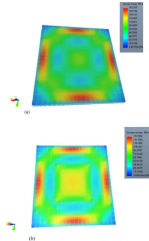
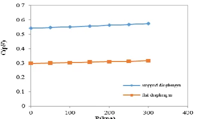
To achieve high sensitivity with minimum nonlinearity, the flat diaphragm is turned to a stepped diaphragm. The simulation results for two flat and stepped diaphragms are shown in Figure 8. As can be seen in Figure 9, the movement of stepped diaphragm under same pressure has been decreased in comparison with flat diaphragms due to the increasing of stress at the diaphragm edges and center. Figure 10 shows the capacitor versus pressure for flat and stepped diaphragms with 6µm thickness. The result illustrates using non-uniform air gap increases capacitance. From Figure 11, the simulated sensitivity is 0.107
whereas the calculated one is 0.128 . The difference between the simulation and the theoretical results is due to the approximation of the formula. In addition, the non-linearity is obtained 1.857% in stepped diaphragm (see Figure 11). Thus, using new design the sensitivity and linearity are improved simultaneously.
Figure 5. Diaphragm displacement under various pressures for flat diaphragm with 5µm thickness
Figure 6. Diaphragm displacement under various pressures for flat diaphragms with 5µm and 6µm thicknesses
Figure 7. The capacitance of sensor versus applied pressure
Figure 8. Diaphragm displacement versus pressures for flat and stepped diaphragms
Figure 9. Stress distribution on a) flat diaphragm b) stepped diaphragm with 6µm thickness under same pressure
KPa fF
KPa fF
KPa fF
0 0.5 1 1.5 2 2.5 3
0 100 200 300 400
D
isp
la
ce
m
en
t
(µ
m
)
Pressure (kPa)
Simulation Theory
0 0.5 1 1.5 2 2.5
0 100 200 300 400
D
isp
la
ce
m
en
t
(µ
m
)
Pressure (kPa)
Flat diaphragm with 5µm thickness
Flat diaphragm with 6µm thickness
0.29 0.295 0.3 0.305 0.31 0.315 0.32 0.325 0.33 0.335 0.34
0 100 200 300 400
C
(p
F)
P(kPa)
Flat diaphragm with 6µm thickness Linear curve fitting
Flat diaphragm with 5µm thickness Linear curve fitting
0 0.5 1 1.5 2 2.5
0 100 200 300 400
D
is
p
lac
em
en
t
(µm
)
Pressure (kPa)
Figure 10. The capacitor versus pressure for flat and stepped diaphragms with 6µm thickness
Figure 11. The sensitivity and non-linearity of the stepped diaphragm with 6µm thicknesses
5. CONCLUDING
In this paper, a new capacitive pressure sensor for tire monitoring system is designed and simulated. In this study, by increasing the thickness of the diaphragm, and converting it to stepped one, the sensitivity and linearity of the sensor are substantially improved. The results show that the sensitivity of the sensor is increased from
0.063 in flat diaphragm to 0.107 in
stepped diaphragm and also the non-linearity is decreased from 2.37 to 1.857%. The sensitivity of the tire pressure sensor with stepped diaphragm is at least 1.6 times more than with flat one.
6. REFERENCES
1. Preethi, A. and Chitra, L., "Comparative analysis of materials for the design of a highly sensitive capacitive type of mems pressure sensor", in Emerging Trends In New & Renewable Energy Sources And Energy Management (NCET NRES EM), IEEE National Conference On, (2014), 1-8.
2. Wei, C., Zhou, W., Wang, Q., Xia, X. and Li, X., "TPMS (tire-pressure monitoring system) sensors: Monolithic integration of surface-micromachined piezoresistive pressure sensor and self-testable accelerometer", Microelectronic Engineering, Vol. 91, (2012), 167-173.
3. Michael Paine, M.G. and Magedara, N., "The role of tyre pressure in vehicle safety, injury and environment", Road Safety
Solutions, (2007) 365-371.
4. Tian, B., Zhao, Y., Jiang, Z., Zhang, L., Liao, N., Liu, Y. and Meng, C., "Fabrication and structural design of micro pressure sensors for tire pressure measurement systems (TPMS)",
Sensors, Vol. 9, No. 3, (2009), 1382-1393.
5. Deepika, A. and Sharma, A., "Virtual prototyping of a mems capacitive pressure sensor for TPMS using intellisuite", in International Symposium on Physics and Technology of Sensors., 25-28.
6. National Highway Traffic Safety Administration, "Tire pressure monitoring systems",Federal Motor Vehicle Safety Standards, 49 CFR (2005) 571 -585.
7. Sharifi, M., Nemati, N. and Abedi, A., "A new mems based capacitive differential pressure sensor with acceptable sensitivity and improved linear region", in Electrical Engineering (ICEE), 22nd Iranian Conference on, IEEE, (2014), 29-32.
8. Meng, G. and Ko, W.H., "Modeling of circular diaphragm and spreadsheet solution programming for touch mode capacitive sensors", Sensors and Actuators A: Physical, Vol. 75, No. 1, (1999), 45-52.
9. Hezarjaribi, Y., Hamidon, M.N., Sidek, R.M. and Keshmiri, S.H., "Analytical and simulation evaluation for diaphragm’s deflection and its applications to touch mode mems capacitive pressure sensors", Australian Journal of Basic and Applied
Sciences, Vol. 3, No. 4, (2009), 4281-4292.
10. Lee, K.-W. and Wise, K.D., "Sensim: A simulation program for solid-state pressure sensors", Electron Devices, IEEE
Transactions on, Vol. 29, No. 1, (1982), 34-41.
11. Eaton, W.P. and Smith, J.H., "Micromachined pressure sensors: Review and recent developments", Smart Materials and
Structures, Vol. 6, No. 5, (1997), 530-539.
12. SujaK, J., Raveendran, E. and Komaragiri, R., "Investigation on better sensitive silicon based mems pressure sensor for high pressure measurement", International Journal of Computer
Applications, Vol. 72, No. 8, (2013), 40-47.
13. Khakpour, R., Mansouri, S.R. and Bahadorimehr, A., "Analytical comparison for square, rectangular and circular diaphragms in mems applications", in Electronic Devices, Systems and Applications (ICEDSA), Intl Conf on, IEEE, (2010), 297-299.
14. Wang, Q. and Ko, W.H., "Modeling of touch mode capacitive sensors and diaphragms", Sensors and Actuators A: Physical, Vol. 75, No. 3, (1999), 230-241.
15. Shahiri-Tabarestani, M., Ganji, B. and Sabbaghi-Nadooshan, R., "Design and simulation of high sensitive capacitive pressure sensor with slotted diaphragm", in Biomedical Engineering (ICoBE), International Conference on, IEEE (2012), 484-489. 16. Ganji, B.A. and Majlis, B.Y., "Analytical analysis of flat and
corrugated membranes for mems capacitive sensors",
International Journal of Nonlinear Dynamics Engineering
Science, Vol. 1, No. 1, (2008), 47-57.
17. Jerman, J., "The fabrication and use of micromachined corrugated silicon diaphragms", Sensors and Actuators A:
Physical, Vol. 23, No. 1, (1990), 988-992.
18. Kressmann, R., Klaiber, M. and Hess, G., "Silicon condenser microphones with corrugated silicon oxide/nitride electret membranes", Sensors and Actuators A: Physical, Vol. 100, No. 2, (2002), 301-309.
19. Soin, N. and Majlis, B.Y., "An analytical study on diaphragm behavior for micro-machined capacitive pressure sensor", in Semiconductor Electronics. Proceedings. ICSE. IEEE International Conference on, IEEE, (2002), 505-510.
KPa
20. Nateri, M. and Ganji, B., "Design of novel high sensitive mems capacitive fingerprint sensor", International Journal of
Engineering, Vol. 25, No. 3, (2012), 167-174.
21. Sharma, A., "Modeling of pull-in voltage and touch-point pressure for mems capacitive transducer with square
diaphragm", Kurukshetra University, Kurukshetra Ph.d Thesis, (2008), 376-382.
22. Damghanian, M. and Majlis, B.Y., "Design of a high sensitivity structure for mems fingerprint sensor", in IEEE International Conference on Semiconductor Electronics, ICSE, (2006).
Design of High Sensitivity and Linearity Microelectromechanical Systems Capacitive
Tire Pressure Sensor using Stepped Membrane
M. Norouznejad Jelodar, B. A. Ganji
Department of Electrical and Computer Engineering, Babol University of Technology, Babol, Iran
P A P E R I N F O
Paper history:
Received 10 December 2015
Received in revised form 02 February 2016 Accepted 03 March 2016
Keywords:
Capacitive Pressure Sensor Sensitivity
Tire Pressure Monitoring System Linearity
هديكچ
رب هلاقم نیا هلپ مگارفاید اب دیدج یکیناکمورتکلا ورکیم ینزاخ راشف رگسح کی یحارط یور
رد هدافتسا دروم یعبرم یا
یطخ ریغ و رگسح تیساسح نازیم نییعت رد یدیلک شقن رگسح مگارفاید راتخاس .تسا هدش زکرمتم ریات راشف لرتنک متسیس
یم افیا نآ یجورخ ندوب اب ،تباث فرط راهچ هداس یعبرم مگارفاید اب ینزاخ راشف رگسح ود راتخاس ادتبا رد اذل .دنک
تماخض هیبش توافتم یاه ساسح نازیم و هدش یزاس
یارب تیاهن رد و هدیدرگ هسیاقم مه اب اهنآ ندوب یطخ ریغ و تی شیازفا
یطخ و تیساسح ندوب
هلپ مگارفاید اب ینزاخ راشف رگسح یفرعم هب ، قیقد نییعت یارب یددع لح کی و هتخادرپ یعبرم یا
رادقم زا رگسح تیساسح هک دهد یم ناشن جیاتن .تسا هدیدرگ هئارا رگسح تیساسح نازیم
fF/KPa
360 / 3 مگارفاید رد
رادقم هب هداس
fF/KPa
731 / 3 هلپ مگارفاید رد زا زین ندوب یطخ ریغ نازیم و شیازفا یا
01 / 2 هب هداس مگارفاید رد دصرد
رادقم 751 / 7 هلپ مگارفاید رد دصرد
یا تسا هتفای شهاک .
نیاربانب حرط نیا رد خ ریغ و تیساسح نازیم
ط ندوب ی راشف رگسح
یات ر دوبهب نامزمه .تسا هتفای
![Disease Management System Design Specification, System Verification and Administration [92 pages]](data:image/gif;base64,R0lGODlhAQABAIAAAP///wAAACH5BAEAAAAALAAAAAABAAEAAAICRAEAOw==)