the Creative Commons Attribution 3.0 License.
Design of a dual linear polarization antenna using split ring
resonators at X-band
Sadiq Ahmed1,2and Madhukar Chandra1
1Department of Microwave Engineering and Electromagnetic Theory, TU Chemnitz, 09126 Chemnitz, Germany 2Engineering College, University of Al-Mustansiriyah, Baghdad, Iraq
Correspondence to:Sadiq Ahmed ([email protected])
Received: 14 December 2016 – Revised: 4 October 2017 – Accepted: 4 October 2017 – Published: 6 November 2017
Abstract. Dual linear polarization microstrip antenna con-figurations are very suitable for high-performance satellites, wireless communication and radar applications. This paper presents a new method to improve the co-cross polarization discrimination (XPD) for dual linear polarized microstrip an-tennas at 10 GHz. For this, three various configurations of a dual linear polarization antenna utilizing metamaterial unit cells are shown. In the first layout, the microstrip patch an-tenna is loaded with two pairs of spiral ring resonators, in the second model, a split ring resonator is placed between two microstrip feed lines, and in the third design, a complemen-tary split ring resonators are etched in the ground plane.
This work has two primary goals: the first is related to the addition of metamaterial unit cells to the antenna struc-ture which permits compensation for an asymmetric current distribution flow on the microstrip antenna and thus yields a symmetrical current distribution on it. This compensation leads to an important enhancement in the XPD in compari-son to a conventional dual linear polarized microstrip patch antenna. The simulation reveals an improvement of 7.9, 8.8, and 4 dB in the E and H planes for the three designs, re-spectively, in the XPD as compared to the conventional dual linear polarized patch antenna. The second objective of this paper is to present the characteristics and performances of the designs of the spiral ring resonator (S-RR), split ring resonator (SRR), and complementary split ring resonator (CSRR) metamaterial unit cells. The simulations are evalu-ated using the commercial full-wave simulator, Ansoft High-Frequency Structure Simulator (HFSS).
1 Introduction
Dual linear polarization antennas have seen noteworthy progress in the last few years for several applications such as weather radar and wireless communication systems. The key merit of a dual linear polarization antenna is that provides two independent communication channels, in the ideal case and thus, increasing channel capacity of the communication systems at the same baseband. As such, the development of dual linear polarization antennas has witnessed many stud-ies and designs particularly, in space polarimetric weather radar applications. Therefore, the demand for such systems is growing exponentially (Mishra, 2013; Luo et al., 2013). More importantly, a dual linear polarization antenna suffers from the most significant drawbacks. The first is related to the mutual coupling between two input ports and the sec-ond is related to the cross polarization patterns. These draw-backs have provided a fertile ground for the research area. Therefore, many studies suggested and implemented various feeding mechanisms and approach to overcome these two problems and improve the performance of antenna system for their widespread applications (Yang et al., 2013; Liang et al., 2005).
polar-(a) (b)
(c) (d)
4 6 8 10 12 14 16
-30 -25 -20 -15 -10 -5 0
Frequency (GHz)
M
ag
ni
tu
de
S
-p
ar
am
et
er
s
(d
B
)
S11 S21 b
a
w g
ℓ
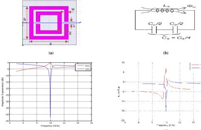
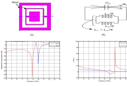
1Figure 1.Spiral ring resonator(a)2-D geometry of S-RR(b)equivalent circuit(c)S-parameters of unit cell(d)permittivity and permeability.
(a) (b)
(c) (d)
L
W Wf
Lf
Lslot
Wslot
g
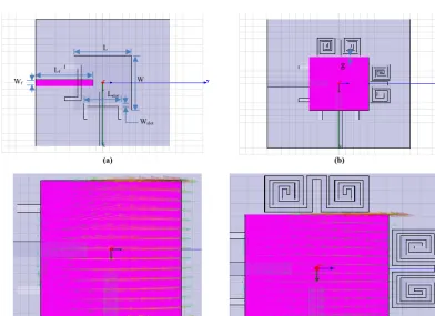
Figure 2.Dual linear polarization antenna(a)2-D geometry of conventional dual linear polarization antenna(b)2-D geometry of proposed
(a) (b)
-200 -150 -100 -50 0 50 100 150 200
-60 -50 -40 -30 -20 -10 0 Angle (degrees) C o & c ro ss p ol a t p la ne 9 0 (d B ) MTM co-pol MTM cross-pol C onv co-pol C onv cross-pol
-200 -150 -100 -50 0 50 100 150 200
-60 -50 -40 -30 -20 -10 0 Angle (degrees) o & c ro ss p ol a t p la ne 0 (d B ) C MTM co-pol MTM cross-pol onv co-pol C onv cross-pol C
Figure 3.Co-cross polarization radiation patterns in(a)E(b)H-planes, for a dual polarized antenna with and without metamaterial.
4 6 8 10 12 14 16
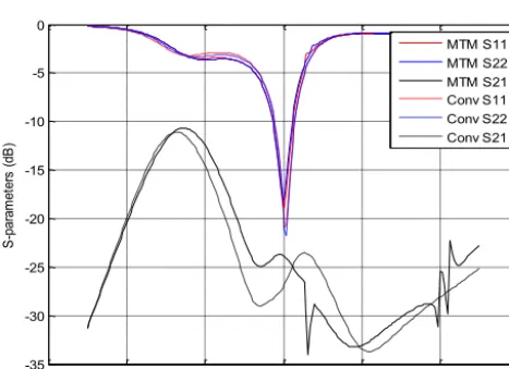
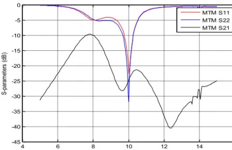
-35 -30 -25 -20 -15 -10 -5 0 Frequency (GHz) S -p ar am et er s (d B ) MTM S11 MTM S22 MTM S21 C onv S11 C onv S22 C onv S21
Figure 4. S-parameters between two orthogonal input ports with
and without S-RR unit cell.
ization pattern. The reason for an asymmetrical current dis-tribution lies in principle characteristic of two perpendicular feeds which place on the nearest two edges while remaining other two edges are without excitation (Liang et al., 2005). To solve this problem, split ring resonators (SRRs) mode of metamaterials are used. Therefore, the SRRs are utilized to compensate the current distribution on the microstrip an-tenna which leads to improvements in the XPD. Metamate-rials (Veselago, 1968) have been used to develop many ap-plications with unique properties (Lin et al., 2004). Meta-materials are utilized in the form of S-RR, SRR, and CSRR structures to represent a single-negative medium and have the properties of a band stop filter (AL-Nuaimi and Whit-low, 2010). This work is organized as follows: the design of a dual linear polarization antenna using a S-RR is presented in Sect. 2. Section 3 is devoted to a dual linear polarization antenna using a SRR design. The design of antenna system
Table 1.Dimensions of a dual linear polarization antenna (all
di-mensions in mm).
parameters L W Lf Wf Lslot Wslot g
8.3 8.3 8.6 1 5.6 0.5 0.2
using CSRRs is presented in Sect. 4. Finally, Sect. 5 contains the conclusions.
2 Design of a dual linear polarized antenna using a spiral ring resonator
This part deals with the design of a patch antenna using two S-RRs which are placed close to the radiator patch.
2.1 Design of a spiral ring resonator as a band stop filter
The topology of the proposed spiral ring resonator (S-RR) and its equivalent network are illustrated in Fig. 1a and b, respectively. The unit cell consists of two S-RRs joined with a stripline of length (`1) and width (w). The
physi-cal dimensions of the S-RR unit cell in our design are: side lengthsa=2.75 mm andb=2.75 mm, the gap between met-alsg=0.2 mm,w=0.3 mm and`1=1.1 mm. Figure 1c
de-picts theS-parameters of the unit cell; it is observed that the S-RR gives stop band properties (S21=-25 dB) at the
parame-(a) (b)
(c) (d)
4 6 8 10 12 14 16
-45 -40 -35 -30 -25 -20 -15 -10 -5 0
Frequency (GHz)
M
a
g
n
it
u
d
e
S
-p
a
ra
m
e
te
rs
(
d
B
)
S11 S21 a
b
g w
s
Figure 5.Split ring resonator(a)2-D geometry of single split ring resonator(b)equivalent circuit of SRR(c)S-parameters of the unit cell
(S11andS21)(d)real values of permittivity, and permeability.
(a) (b)
Figure 6.Geometry of a dual linear polarization antenna(a)2-D geometry of a dual linear polarization antenna after adding SRR between
two microstrip feed lines(b)current distribution due to horizontal port after adding SRR.
ters (εandµ)of unit cell based on the retrieval method as follows (Chen at al., 2004; Sadiq and Chandra, 2016):
S11=
R01 1−ej2nβh
1−R201ej2nβh (1)
S21=
1−R012
ej2nβh
1−R201ej2nβh (2)
z= ±
s
(1+S11)2−S212
(1−S11)2−S212
(3)
ej nβh= S21
1−S11zz−+11
(4)
n= 1
βh
hn h
lnej nβh
i
00+2mπo
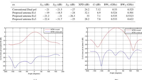
ples ofS-parameters, XPD and BW for two ports.
ex S11(dB) S22(dB) S21(dB) XPD (dB) G(dB) BW1(GHz) BW2(GHz)
Conventional Dual pol −21 −21.5 −27 24.2 7.12 0.53 0.525 Proposed antenna Ex1 −19 −18.5 −24 32.1 6.9 0.524 0.501 Proposed antenna Ex2 −21.2 −21 −26.3 33 7.1 0.535 0.5323 Proposed antenna Ex3 −22.4 −31.7 −25 28.2 7.8 0.533 0.622
(a) (b)
-200 -150 -100 -50 0 50 100 150 200
-45 -40 -35 -30 -25 -20 -15 -10 -5 0 5
Angle (degrees)
C
o
&
c
ro
ss
p
ol
a
t
pl
an
e
90
(
dB
)
MTM co-pol MTM cross-pol
-200 -150 -100 -50 0 50 100 150 200
-50 -45 -40 -35 -30 -25 -20 -15 -10 -5 0
Angle (degrees)
C
o
&
c
ro
ss
p
ol
a
t
pl
an
e
0
(d
B
)
MTM co-pol MTM cross-pol
Figure 7.Co-cross polarization radiation patterns in(a)E(b)H-planes, for a dual linear polarization with metamaterial.
4 6 8 10 12 14 16
-35 -30 -25 -20 -15 -10 -5 0
Frequency (GHz)
S
-p
ar
am
et
er
s
(d
B
)
S11 S22 S21
Figure 8. S-parameters between two orthogonal input ports with
SRR unit cell.
where (.)0represents the real component and (.)00 the imag-inary part of the complex number; S11 andS21 are the
re-flection and transmission coefficients, respectively; nis the refractive index;R01is(z−1)/(z+1);zis the impedance;
mis the branch due to the periodicity of the sinusoidal func-tion;β is the wave number constant; h is the height of
sub-strate material. Permeability and permittivity can be written by the following equations (Numan and Sharawi, 2008):
µr=nz (6)
εr=n/z (7)
distribu-(a) (b)
(c) (d)
4 5 6 7 8 9 10 11 12 13 14
-50 -45 -40 -35 -30 -25 -20 -15 -10 -5 0
Frequency (GHz)
M
ag
ni
tu
de
S
-p
ar
am
et
er
s
(d
B
)
S11 S21
4 5 6 7 8 9 10 11 12 13 14
-20 0 20 40 60 80 100
Frequency (GHz)
a
nd
real
real
Metal
Figure 9.Complementary split ring resonator(a)2-D geometry of a CSRR(b)equivalent circuit of a CSRR(c)S-parameters of the unit cell
(S11andS21)(d)real values of permittivity, and permeability.
tion along the proposed patch antenna provides a good indi-cation for improving the XPD. It is observed that the current distribution becomes more symmetric after adding the two S-RRs as depicted in Fig. 2c and d, which show the current distribution before and after the addition of unit cells due to horizontal port. With such a setup, the XPD can be enhanced. Figure 3a and b displays the normalized co-cross polar-ization radiation patterns in principle planes for conventional and proposed dual linear polarized antennas. It is observed that a significant improvement in the XPD in comparison to the original dual linear polarized patch antenna (without S-RRs). The simulation reveals an increase of 7.9 dB in the XPD as compared to the conventional antenna. The reflec-tion and isolareflec-tion coefficients between two orthogonal input ports with and without S-RR inclusions are shown in Fig. 4. It is observed that the isolation becomes worse by 3 dB and the return loss for two input ports are S11= −19 dB and
S22= −18.5 dB at the resonance frequency. The dimensions
of a dual linear polarized antenna system are listed in Table 1.
3 Design of a dual linear antenna using a split ring resonator with a frequency of 10 GHz
This section presents the design of a dual linear polarization microstrip antenna with two orthogonal aperture-coupling
microstrip feed lines. In this design, the SRRs are placed be-tween two microstrip feed lines.
3.1 Design of the SRR as a Band Stop Filter
Figure 5a and b shows the 2-D structure of the SRR which consist of two concentric square rings and its equivalent cir-cuit, respectively. The metamaterial structure has been imple-mented on a RO4350C high-frequency laminate (εr=3.48, the thickness of the substrate is 0.508 mm and a metal thick-ness of the copper cladding of 35 µm). The geometry of SRR is optimized in order to be used with a feeding system for a dual linear polarized patch antenna.The parameters of this filter are: side lengthsa=3 mm,b=2.9, gap between met-als g=0.2, slot width s=0.2 mm, and width of stripline w=0.3 mm.
(a) (b)
(c)
Patch Sub. 1
ground
Sub. 2
CSRRs Slots
Microstrip lines
Figure 10.Geometry of a dual linear polarization antenna(a)2-D geometry of a dual linear polarization antenna after adding a pair of CSRR
(b)3-D structure of the antenna system(c)Current distribution flow on the patch antenna after adding CSRR.
(a) (b)
-200 -150 -100 -50 0 50 100 150 200
-60 -50 -40 -30 -20 -10 0 10
Angle (degrees)
o-cr
os
s
po
l a
t p
la
ne
C
=
90
(
dB
)
MTM co-pol MTM cross-pol
-200 -150 -100 -50 0 50 100 150 200
-50 -40 -30 -20 -10 0 10
Angle (degrees)
C
o-cr
os
s
po
l a
t
pl
an
e
=
0
(d
B
)
MTM co-pol MTM cross-pol
Figure 11.Linear co-cross polarization radiation patterns in(a)E-(b)H-planes, for a dual linear polarization with metamaterial.
two microstrip feed lines. The microstrip feed has a width of 1mm, which is corresponding to a characteristic impedance of 50. Figure 5c displays theS-parameters of the unit cell. It can be seen that SRR provides to stop band properties (S21= −41 dB) at the center frequency of 10 GHz. The real
4 6 8 10 12 14 16 -45
-40 -35 -30 -25 -20 -15 -10 -5 0
Frequency (GHz)
S
-p
ar
am
et
er
s
(d
B
)
MTM S11 MTM S22 MTM S21
Figure 12.S-parameters between two orthogonal input ports.
Figure 13.3-D radiation pattern of antenna system.
3.2 Design of a dual linear polarization antenna using split ring resonators between two microstrip lines
In this part, a SRR is placed between two microstrip feed lines as shown in Fig. 6a. The space between SRRs and the microstrip feed line is 0.1 mm. More symmetry in the current distribution is observed after adding of unit cells as shown in Fig. 6b. Linear, co-cross polarization patterns in the E and H planes are depicted in Fig. 7a and b, which shows a significant improvement of the XPD in compari-son to the conventional dual linear polarized antenna. The simulation reveals an improvement of 8.8 dB in the XPD as compared to the conventional antenna. Figure 8 shows the reflection and mutual coupling coefficients between two or-thogonal input ports. It is noticed that the mutual coupling becomes a little worse by 0.7 dB (S21= −26.3 dB) and the
reflection coefficients for the two input ports areS11= −21.2
andS22= −21 dB at the center frequency as demonstrated in
Table 2.
4 Design of a dual linear antenna using a
complementary split ring resonator with a frequency of 10 GHz
This part presents the design of a microstrip antenna with two orthogonal aperture-coupling microstrip feed lines. In this design, the complementary split ring resonators (CSRRs) are used.
4.1 Design of a complementary split ring resonator as a Band Stop Filter
The complementary split ring resonator (CSRR) is per-formed by etching SRR in the ground plane as illustrated in Fig. 9a. It has approximately the same shape of the SRR structure. The CSRRs display inverse properties of those of the SRRs. For example, The SRR works as a magnetic dipole while the CSRR behaves as an electric dipole. Thus CSRR produces negative permittivity (Re(ε)< 0) instead of nega-tive permeability (Re(µ)< 0) near the resonance frequency. Figure 9b shows the equivalent circuit of CSRR (Al-Nuaimi and Whitlow, 2010). All dimensions of the CSRRs have been chosen identical to their SRR counterparts so that the operat-ing frequency of the band stop filter is also around 10 GHz. The distance between the microstrip feed line and the CSRRs is determined by the height of the substrate material. Fig-ure 9c displays theS-parameters of a CSRR, it is observed that CSRR offers to stop band properties (S21= −30 dB) at
the transition frequency of 10 GHz. The real values of the constitutive parameters (εandµ)are shown in Fig. 9d and it may be noticed that the real values of permittivity are purely negative which leads to a band-rejection filter in this region.
4.2 Design of a dual linear polarization antenna using two pairs of complementary split ring resonators (CSRR)
Figure 10a and b shows the 2-D and 3-D geometry of a dual linear polarization antenna using two pairs of the CSRR unit cells, respectively. It is noticed that more symmetry in the current distribution flows on radiator patch after adding of the two pairs of unit cells as shown in Fig. 10c. Figure 11a and b shows the linear co-cross polarization radiation pat-terns in the E and H planes at the broadside. The simulation reveals that the XPD of 28.2 dB, which means that enhance-ment of 4 dB in the XPD as compared to the conventional antenna. Figure 12 shows the reflection and mutual coupling coefficients between two orthogonal input ports with two pairs of CSRRs. It is observed that the mutual coupling be-comes worse by 2 dB (S21= −25 dB) and the input
reflec-tion coefficients for the two input ports areS11= −22.4 and
S22= −31.7 dB at the resonance frequency as demonstrated
In this paper, a novel approach (using metamaterials) is used to enhance the XPD for a dual linear polarization patch an-tenna at the frequency of 10 GHz. This improvement is ob-tained by placing two S-RRs close to the microstrip patch an-tenna, placing a SRR between two microstrip feed lines, and etching two pairs of CSRRs in the ground plane. An improve-ment in the XPD by 8.8 dB as compared to the conventional dual linear polarization antenna is noticed. The antenna sys-tem has several advantages involving a simple structure, and metamaterial inclusions occupied the very small area, which makes the proposed metamaterial more useful for the design of dual linear polarization antennas. The proposed antenna is very compact as compared to a conventional dual linear polarization antenna and has the desired improved character-istics.
Data availability. The paper depends on the design of antenna us-ing software and Matlab program.
Competing interests. The authors declare that they have no conflict of interest.
Special issue statement. This article is part of the special issue “Kleinheubacher Berichte 2016”. It is a result of the Klein-heubacher Tagung 2016, Miltenberg, Germany, 26–28 September 2016.
Edited by: Gerd Wanielik
Reviewed by: three anonymous referees
Al-Nuaimi, M. K. T. and Whitlow, W. G.: Compact microstrip band-stop filter using SRR and CSSR: Design, simulation, and results, Antennas Propag. (EuCAP), Proc. Fourth Eur. Conf., 2–6, 2010. Chen, X., Grzegorcezyk, T. M., Wu, B., Pacheco, J., and Kong, J. A.: Robust Method to Retrieve the Constitutive Effective Param-eters of Metamaterials, Physics Review E, 70, 1–7, 2004. Liang, X. L., Zhong, S. S., and Wang, W.: Design of A Dual
Po-larization Microstrip Patch Antenna with excellent PoPo-larization Purity, Microw. Opt. Techn. Let., 44, 329–331, 2005.
Lin, I. H., DeVincentis M., Caloz, C., and Itoh T.: Arbitrary dual-band components using composite right/left-handed transmis-sion lines, IEEE T. Microw. Theory, 52, 1142–1149, 2004. Luo, K., Ding, W., Hu, Y., and Cao, W.: Design of Feed
Dual-Polarized Microstrip Antenna with High Isolation and Low Cross Polarization, Progress In Electromagnetics Research Letters, 36, 31–40, 2013.
Mishra, P. K., Jahagirdar, D. R., and Kumar, G.: An Array of Broad-band Dual Polarized Electromagnetically Coupled Microstrip Antennas, Prog. Electromagn. Res., 44, 211–223, 2013. Numan, A. B. and Sharawi, M. S.: Extraction of Material
Parame-ters for Metamaterials Using a Full-Wave Simulator, IEEE An-tenn. Propag. M., 55, 202–211, 2013.
Sadiq, A. and Chandra, M.: Cross Polarization Discrimination Enhancement of a Dual Linear Polarization Antenna Using Metamaterials, UKSim-AMSS 18th International Conference on Computer Modelling and Simulation, 366–371, 2016.
Veselago, V.: The electrodynamics of substances with simultane-ously negative values ofε andµ, Soviet Physics Uspekhi, 10, 509–514, 1968.