R E S E A R C H
Open Access
DeviceEditor visual biological CAD canvas
Joanna Chen
1,2, Douglas Densmore
1,2,3, Timothy S Ham
1,4, Jay D Keasling
1,2,5,6and Nathan J Hillson
1,2*Abstract
Background:Biological Computer Aided Design (bioCAD) assists thede novo design and selection of existing genetic components to achieve a desired biological activity, as part of an integrated design-build-test cycle. To meet the emerging needs of Synthetic Biology, bioCAD tools must address the increasing prevalence of combinatorial library design, design rule specification, and scar-less multi-part DNA assembly.
Results:We report the development and deployment of web-based bioCAD software, DeviceEditor, which provides a graphical design environment that mimics the intuitive visual whiteboard design process practiced in biological laboratories. The key innovations of DeviceEditor include visual combinatorial library design, direct integration with scar-less multi-part DNA assembly design automation, and a graphical user interface for the creation and modification of design specification rules. We demonstrate how biological designs are rendered on the DeviceEditor canvas, and we present effective visualizations of genetic component ordering and combinatorial variations within complex designs.
Conclusions:DeviceEditor liberates researchers from DNA base-pair manipulation, and enables users to create successful prototypes using standardized, functional, and visual abstractions. Open and documented software interfaces support further integration of DeviceEditor with other bioCAD tools and software platforms. DeviceEditor saves researcher time and institutional resources through correct-by-construction design, the automation of tedious tasks, design reuse, and the minimization of DNA assembly costs.
Keywords:bioCAD, Visual design abstraction, Correct-by-construction design, Design specification rules, Combina-torial library, DNA assembly
Background
The development of bioCAD software is paramount to our future capacity to rapidly design increasingly com-plex biological systems for the predictable and reprodu-cible production of biofuels and bio-based chemicals [1]. When considering a DNA construction task, researchers must choose from a rapidly expanding list of candidate gene orthologs and expression systems. BioCAD tools (reviewed in [2-4]) make it possible to automatically query parts repositories for putative design components [5] and model the performance of candidate component combinations [6-9]. These software tools can also address design workflow bottlenecks by providing can-vases for abstractly visualizing and arranging genetic components [10] and automating the design and execu-tion of the DNA assembly process [11,12] (reviewed in [13,14]).
However, despite the growing utility of bioCAD soft-ware, three critical design automation needs within the Synthetic Biology community remain unmet: 1) software integration, 2) combinatorial library design visualization, and 3) user-specifiable design rules. First and foremost, the end-to-end design process is crippled by the lack of integration among individual software tools that specia-lize in modelling, DNA assembly, or genetic component (e.g., ribosomal-binding site (RBS) [15]) design. It is hoped that emerging data exchange standards such as the Synthetic Biology Open Language (SBOL) [16], along with open and well-documented software inter-faces, will enable future bioCAD platforms and mini-mize tool redundancy. Second, combinatorial libraries of fusion proteins and metabolic pathways have become increasingly utilized for optimizing biofuel and based chemical production [17-19], yet no visual bio-CAD tools currently support the combinatorial library design process. Algorithms have been developed to automate the enumeration of all combinations of genetic
* Correspondence: [email protected]
1Fuels Synthesis Division, Joint BioEnergy Institute, Emeryville, CA 94608, USA
Full list of author information is available at the end of the article
components that meet a given set of design specifica-tions [12,20], but the input of the DNA sequence infor-mation and the execution of these algorithms is not visually intuitive. More useful would be an interface that captures a familiar design workflow, such as the ubiqui-tous dry-erase whiteboard, to facilitate the spatial arrangement of components to be combined. Third, while bioCAD tools have been developed to visualize specification-compliant designs [21] or exploit composi-tion grammars to guide the visual arrangement of parts [10], the underlying specifications and grammars must be defined within a programming-like language [20,22] or remain opaque by being neither viewable nor modifi-able by the user [10].
Towards addressing these unmet design needs, we have developed DeviceEditor, a bioCAD canvas that enables researchers to spatially organize abstractions of biological components. DeviceEditor assists the aggrega-tion and arrangement of the DNA sequences of genetic components (e.g., ribosomal-binding sites, promoters and terminators, and metabolic pathway genes) to be assembled towards a desired functionality. DeviceEditor ensures that designs are “correct-by-construction”, because within its confines researchers are prevented from performing invalid operations (e.g. referencing DNA base-pair 500 within a 100 base-pair sequence). To the best of our knowledge, DeviceEditor is the first bioCAD tool that visualizes combinatorial DNA library
design, provides a graphical user interface for the crea-tion and modificacrea-tion of design specificacrea-tion rules, and is directly integrated with scar-less multi-part DNA assembly design automation. Taken together, these innovations benefit researchers and their institutions through correct-by-construction design, the automation of tedious tasks, design reuse, and the minimization of DNA assembly costs.
Results
The DeviceEditor bioCAD canvas provides a web-based visual design environment (Figure 1) that mimics the familiar whiteboard design process practiced in biologi-cal laboratories. An online user’s manual [23] provides an introduction to bioCAD, an overview of DeviceEditor functionality, and step-by-step how-to video demonstrations.
DeviceEditor design process
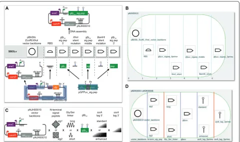
To begin the process, the genetic components or biolo-gical “parts” that will comprise the design are defined. This is accomplished by first selecting a standardized icon from the Synthetic Biology Open Language Visuali-zation extension (hereafter SBOLv) [25] palette to repre-sent a given component (e.g., promoter, 5’ UTR, terminator). If no icon in the SBOLv palette fully cap-tures the essence of a part (e.g., the pBbS8c-rfp back-bone consists of more than just an “Origin of
Replication”, Figure 2), the most appropriate option or a blank generic icon can be selected. While visually evoca-tive, from the outset the icons do not contain actual information. A DNA sequence is then mapped to the part icon (Figure 2), either copied from third party soft-ware or retrieved from a sequence file. DNA sequences in DeviceEditor do not need to be “packaged” in any particular format, such as the BioBricks format [26]. Each part is then set to either “Forward” (default) or
“Reverse” to indicate the desired orientation of the part in the resulting construct. Once all of the desired com-ponent part icons have been defined, they are arranged from left to right in a“collection”to match their 5’to 3’ order in the target DNA construct (Figure 3A, B; Addi-tional file 1). For combinatorial designs, interchangeable
component icons are arranged in the same vertical col-lection “bin” (Figure 3C, D; Additional file 2). The design is then specified to produce a “Circular”(default) or“Linear”DNA construct (Figure 1, top right).
To limit the total number of times a part may appear in a given construct, to prevent any two parts from appearing together in the same construct, or to ensure that two given parts always appear together in the same construct, Eugene design specification rules [20] may be added. These rules can ensure that two parts always appear together in the same construct, prevent two parts from appearing together in the same construct, and limit the total number of times a part may appear in a construct. For example, if prior research demon-strated that the short linker sequence must be used with
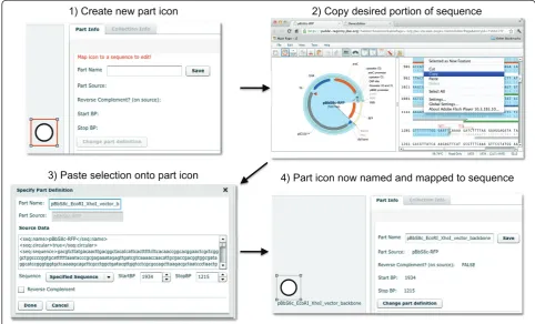
1) Create new part icon 2) Copy desired portion of sequence
3) Paste selection onto part icon 4) Part icon now named and mapped to sequence
Figure 2Mapping a DeviceEditor part icon to an annotated DNA sequence. A new part icon on the design canvas (top left) is created by clicking on the desired SBOLv icon (here“Origin of Replication”) in the left panel of the user interface (Figure 1). At this point, a DNA sequence has yet to be mapped to the part icon. In a separate browser-tab or software application, the desired portion of a DNA sequence (here the pBbS8c-rfpbackbone [27] spanning fromXhoI toEcoRI) is selected and copied (top right) to the clipboard. Third-party software (here VectorEditor) may embed meta-data (including jbei-seq format [28] sequence data) into the clipboard along with the plain-text DNA sequence selection (see Methods). Returning to DeviceEditor, the copied DNA sequence is pasted (mapped) from the clipboard onto the part icon. Clipboard meta-data provides DeviceEditor with the selected start and stop base pairs (here 1934 to 1215) within the circular source sequence, along with the source’s name (here pBbS8c-rfp), entire sequence, and feature annotations (displayed in the“Source Data”field; bottom left). If the third-party software (e.g. ApE [29]) does not embed this meta-data, the sequence annotations are not transferred to DeviceEditor, and the user must specify the source name and the selected start and stop base-pairs within the copied sequence. The user may alternatively map a Genbank-format sequence file to the part icon, which preserves the source name and feature annotations. The name for the part icon (here
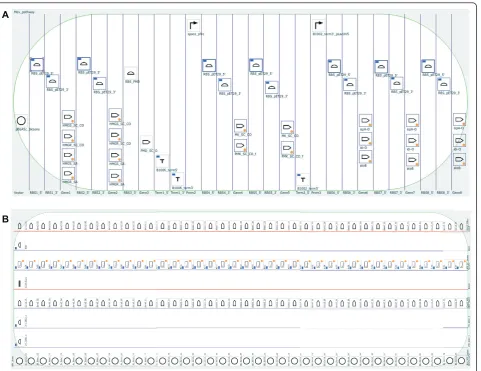
the tagsig1(Figure 3C) to achieve proper GFPuv locali-zation, Eugene rules can be specified (Figure 4; Addi-tional file 3) to ensure that the short linker is always constructed together with sig1. This would eliminate two (of the eight possible) combinations that have the short linker following the tagsig2. For metabolic path-way library designs that vary enzyme ortholog selection and gene ordering [30,31], Eugene rules can ensure that orthologs and individual enzymes are not repeated in the same construct. The application of just 9 Eugene rules to the design shown in Figure 5A eliminates 1632 undesirable combinations that do not constitute com-plete pathways, out of 1728 total possible combinations. Also, the set of “desirable” combinations may evolve with additional experimental information, for example, if evidence arises that two particular enzyme orthologs do
not operate well together in E. coli. A key point is that this additional information only requires the modifica-tion of a few design rules to update the desirable set of combinations, rather than complete re-designs. This is important because toggling a few design rules enables researchers to re-use designs as they switch between microbial hosts and as they gain experimental insight. For selection-based experiments exploiting pooled-library designs [32], Eugene rules can ensure that each vector backbone is always constructed together with its one-to-one corresponding user-specified DNA barcode (Figure 5B), facilitating and reducing the cost of sequence-identifying top performers.
To integrate physical implementation (i.e. DNA assem-bly) strategy into the DeviceEditor design process, the means by which the parts should be assembled together gfpuv_sig.pep
gfpuv_sig.pep gfpuv_sig.pep
RBS PBAD dbl term oriSC101 t0 PBAD araC camR
E X ☆ ☆
pBbS8c-rfp PBAD dbl term oriSC101 t0 PBAD araC camR rfp
E Bg Ba X
RBS
rfp
rfpf
pBbS8c-c-rr
pBbS8cBbS8BbBbbbS8bS
oriiSC101
camR c ori araC g g RBSS RBSS RBS RBS pBbS8c
EcoRI/XhoI vector backbone gfpuv sig.pep 5’ XhoI silent mutation gfpuv sig.pep middle gfpuv sig.pep 3’ BamHI silent mutation SBOLv
gfpuv_sig.pep
pGFPuv_sig.pep Ba X
_
_ig.. _ _
_ _sig.sig..
v v v v v v v v v___ v v v v v
gfpuvvvvvvvvvvvv
gfp ppppppepppp
DNA assembly dbl term oriSC101 t0 araC camR
gfpuv_sig.pep ☆ ☆ RBS PBAD pNJH00010 RBS
RBS fpuvvv _sig. .pep
DN
oriiSC101
N-terminal signal peptide
Gly/Ser linker gfpuv
ssrA tag 5’
or or X
standard enhanced or long short sig1 sig2
X X gfpuv
☆ ☆ ☆ ☆ pNJH00010 vector backbone X ssrA tag 3’ X dbl term oriSC101 t0 araC camR RBS PBAD pNJH00010 A B C D
Figure 3Example biological designs rendered on the DeviceEditor canvas. (A) pNJH00010 [12] consists of seven components: the
(i.e.“forced assembly strategies”) may optionally be pre-scribed for each part (Figure 4A, top right). Part icons with forced assembly strategies are visually distinguished with a blue rectangle indicator light at the top left (Fig-ure 4A, left). Additional aspects of DNA assembly strat-egy may be further customized in the “Collection Info” panel (Figure 1, right). For any given bin in a collection, a“direct synthesis firewall” may be set to“true”to pre-vent the extension of DNA synthesis through the assem-bly junction [12] to the right of the bin, as visually indicated by a red vertical line between bins (Figure 3D). The optional “forced relative overhang/overlap” position for each bin prescribes the overhang/overlap position of the assembly junction [12] to the right of the
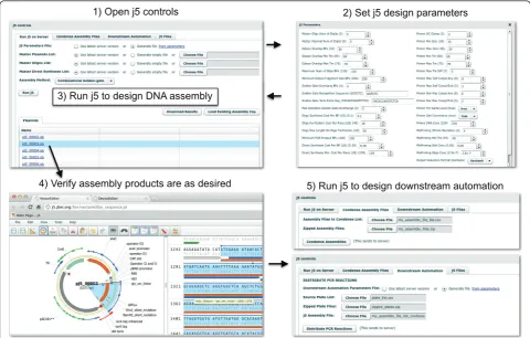
bin. Finally, the forced assembly strategy for each bin is displayed but is not directly modifiable, as it is deter-mined by the forced assembly strategies of the parts that the bin contains. To automate DNA assembly, DeviceE-ditor submits the design contained within the collection to j5, a web-based software tool for designing cost-opti-mized, scar-less, multi-part, DNA assembly protocols [12] (Figure 6, top). Part icons peripheral to the collec-tion are not submitted as part of the design to j5. Once users have visually verified that the desired constructs are correctly designed, DeviceEditor can also direct j5 to design downstream automation processes, such as con-densing multiple assembly files and distributing PCR reactions by annealing temperature (Figure 6, bottom).
A
B
Design process acceleration and correct-by-construction design
DeviceEditor accelerates the design process by relieving the user of tedious routine tasks. For example, sequence annotations and other meta-data are retained when sequences are copied via a compatible clipboard format (see Methods) and pasted onto part icons (Figure 2), or mapped from Genbank format sequence files, obviating the need to re-annotate sequences post-assembly. Part icons can be copied and pasted between concurrent DeviceEditor sessions, enabling the re-use of previously defined parts. Also, DeviceEditor provides hyperlink shortcuts to view j5-assembled design sequences in Vec-torEditor [33,34] (Figure 6) for rapid visual design feedback.
The DeviceEditor correct-by-construction design pro-cess prevents common mistakes. Within the confines of DeviceEditor, the user is not able to perform invalid design modifications. For example, icons for repeated parts are internally linked together (Figure 5A), so that when one instance of a part is modified, all instances are updated in unison, precluding the persistence of obsolete information or the introduction of inconsistencies between repeated parts. DeviceEditor’s correct-by-construction features also benefit j5 DNA assembly design automation [12]. The j5 web-form interface [35] requires the user to upload several comma-separated value (CSV) input files. When manually preparing these CSV input files with spreadsheet software (e.g. Excel, Open Office), there are no safeguards against mistyping start and stop base-pair numbers, or placing a
A
B
direct synthesis firewall at an unintended assembly junc-tion. Since spreadsheet software does not constrain the user’s input, j5 design parameters may be specified out of their acceptable ranges, part names may incorporate typo-graphical errors or prohibited characters, and sequence file names may be mistakenly entered instead of sequence display IDs (a subtle, yet common point of frustration). In contrast with the manual preparation of CSV input files, the DeviceEditor interface for j5 ensures that design para-meters fall within their acceptable ranges (Figure 6), vali-dates the uniqueness and correctness of part names, automatically extracts sequence display IDs, prevents start and stop base-pair numbering mistakes (Figure 2), and visualizes the selected placement of direct synthesis fire-walls (red vertical lines in Figures 3D and 5B). DeviceEdi-tor’s correct-by-construction features can optionally
prevent the user from moving a part icon with a
“DIGEST”forced assembly strategy to the first collection bin, as this would be problematic for downstream j5 DNA assembly design [12]. Finally, DeviceEditor pre-empts sub-stantially increased DNA assembly costs by visually alert-ing the user if two parts in the same bin have disparate forced assembly strategies, which greatly limits the combi-natorial re-use of assembly fragments [12]. Part icons with forced assembly strategies differing from their bin are visually distinguished by a red rectangle indicator light at top left (Figure 4A, left).
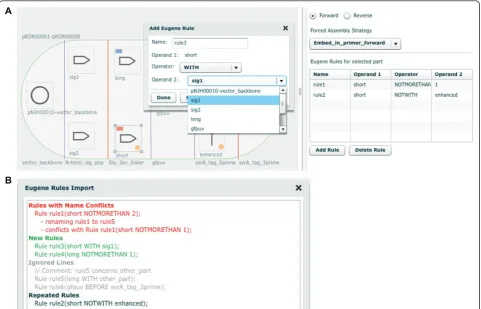
Graphical user interface for creating and modifying Eugene biological design specification rules
Several bioCAD tools (e.g. Clotho [8,36] and GenoCAD [10,37]) harness biological specification rules and
2) Set j5 design parameters
4) Verify assembly products are as desired ) Verify 5) Run j5 to design downstream automation ) j g
1) Open j5 controls
3) Run j5 to design DNA assembly
Figure 6Running j5 from within DeviceEditor. The j5 button at the top left of the user interface (Figure 1) is clicked to open the j5 controls dialog box (top left). The j5 design parameters [12] may be customized or returned to their default values by clicking the“from parameters”link at the top right of the“Run j5 on Server”tab (top left), which opens the j5 Parameters dialog box (top right). Otherwise, the user’s latest set of design parameters (stored on the j5 server) will be employed. Similarly, the user’s latest lists of plasmids, oligos, and direct syntheses will be used (shown here), unless empty or alternate lists are specified. For single construct designs (Figure 3B), the assembly method may be either“SLIC/ Gibson/CPEC”or“Golden-gate”. For combinatorial designs (Figure 3D), the assembly method may be either“Combinatorial SLIC/Gibson/CPEC”or
expression grammars to constrain designs, but the underlying rules and grammars are not viewable or modifiable through the design tools themselves. This can be problematic for design specification rule lan-guages such as Eugene [20] that currently rely on name-matching for part identification, since simple typogra-phical errors can result in referencing incorrect or non-existing parts, and identical names (e.g., “ vector_back-bone”) for distinct parts can result in the misapplication of rules. DeviceEditor’s graphical user interface for creating and modifying design specification rules (Figure 4A) and its Eugene rules file import feature (Figure 4B) prevent typographical mistakes by constraining new rules to supported operators (e.g. WITH) and operands (i.e. part icons) presently on the design canvas. Part icons associated with Eugene rules are visually identified by an orange circle indicator light at bottom right (Fig-ure 5A). DeviceEditor also prevents the misapplication of rules by 1) not allowing distinct parts to have the same name and 2) displaying all rules that specifically apply to the selected part icon (Figure 4A), precluding the need to search through thousands of unrelated rules. While DeviceEditor currently only supports a sub-set of Eugene rules (NOTMORETHAN, WITH, and NOTWITH), future development will expand this list towards more complete coverage.
Mechanisms for integration with other bioCAD software
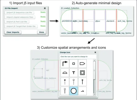
While bioCAD enables thede novodesign or selection of existing component parts to achieve a given biological activity, many of these tools (e.g. the RBS Calculator [15] and GLAMM [5]) specialize in a subset of genetic components (e.g. RBS sequences or metabolic enzyme genes) and are not directly integrated with downstream DNA assembly design automation. DeviceEditor assists the aggregation and arrangement of DNA sequences arising from disparate sources. There are three mechan-isms to transfer component information from other bio-CAD tools to DeviceEditor: copying and pasting (mapping) components into DeviceEditor (Figure 2), CSV and sequence files (i.e. Genbank format) (Figure 7), and DeviceEditor design files (see Methods). The latter two mechanisms are preferable for transferring multiple components to reconstitute complex designs (Figure 5), since copying and pasting is currently limited to one component at a time. CSV and sequence files are advan-tageous in that they are straightforward for third-party software to generate, although they convey less tion (e.g. CSV files omit SBOLv icon selection informa-tion, Figure 7) than DeviceEditor design files. SBOL [16], a promising emerging data exchange standard, is an anticipated fourth mechanism for integrating Devi-ceEditor with other bioCAD software. Further develop-ment of DeviceEditor will support importing SBOL
XML once the XML serialization of SBOL has been firmly established [38].
Discussion
DeviceEditor standardizes visual abstraction with SBOLv icons. Consider the biological components as presented in Figure 3C, such as the centrifugal arrows for N-term-inal signal peptides, and sinusoidal squiggles for Gly/Ser linkers. Those unfamiliar with these ad hoc visual abstractions would need to rely on the corresponding textual descriptions to determine what they actually refer to. In contrast, the DeviceEditor design canvas, as represented in Figure 3D, allows anyone familiar with SBOLv to confidently interpret the design at the granu-larity of the standardized icons, even without supple-mentary text. The use of SBOLv icons is especially compelling for rapid at-a-glance assessment of compo-nent ordering and combinatorial variations within more complex designs (Figure 5). Visual inspection of large designs may also reveal design concepts, constraints, or requirements that were previously unknown. While SBOLv icons themselves are standardized, the user may associate parts and icons in a non-standard, misleading manner. To mitigate this risk, DeviceEditor could be further developed to standardize the SBOLv icon selec-tion process, with parts defying SBOLv categorizaselec-tion represented by blank generic icons. Further DeviceEditor development could also support user-added icons en routeto their formal SBOLv incorporation.
be for bioCAD has yet to be seen. For j5 in particular (and by extension DeviceEditor), sequence context (e.g. the DNA template in which a part resides) is important for safeguarding against off-target DNA oligo priming. However, SBOL currently omits this and other poten-tially valuable design information (such as how DNA components are to be arranged within a combinatorial collection), just as SBOLv does not adequately capture the essence of every part. The extent to which these partial omissions can and should be resolved will be an ongoing question for the Synthetic Biology community. DeviceEditor provides an environment to further investi-gate these issues through the targeted exploration of specific design scenarios.
DeviceEditor’s correct-by-construction and design visualization features serve as the first steps towards
process automation and can offer substantial time- and resource-saving benefits. Consider a Eugene rule for a part named“ispA” that is intended to limitispAto one copy per construct. In Figure 5A, since theispA part is instead named“ispA-O”, applying this“ispA” rule would be ineffective and insufficient to prevent the construc-tion of 112 undesired plasmid combinaconstruc-tions that contain two or three copies ofispArather than complete meta-bolic pathways. In DeviceEditor, these part name over-sights are automatically prevented, since it would not be possible to create Eugene rules for a part named“ispA” for the design in Figure 5A. Furthermore, the lack of Eugene rule indicator lights for the repeated “ispA-O” parts on the design canvas would provide visual cues that something was amiss. Next, consider a misplace-ment of a direct synthesis firewall after gene 3 (eighth
1) Import j5 input files
2) Auto-generate minimal design
3) Customize spatial arrangements and icons
bin) in Figure 5B, rather than before gene 3 as desired. This mistake could result in the purchase of 1444 synthesized DNA fragments spanning the barcode to gene 3 (all pair-wise combinations of barcode and gene 3 variants) rather than the intended 76 fragments (38 barcodes plus 38 gene 3 variants) [12]. While this would be an easy mistake to make when preparing j5 input files with spreadsheet software, DeviceEditor’s promi-nent red firewall visualization makes an incorrect fire-wall placement difficult to miss. Some benefits of DeviceEditor correct-by-construction design are more difficult to precisely estimate, but are nonetheless com-pelling given the large potential downstream risks posed by the errors they prevent. While incorrect start or stop base-pair numbering (Figure 2) and inconsistent defini-tions for repeated parts (e.g. the three repeats of“ ispA-O” in Figure 5A) may be extremely subtle (e.g. one base-pair off), they may have dramatic negative conse-quences (e.g. mRNA secondary structure disruption) and require extensive detective work to resolve and incur significant time and resource losses. Copying and pasting visually selected DNA fragments from VectorE-ditor in to DeviceEVectorE-ditor (Figure 2), along with internally linked repeated parts (Figure 5A), pre-empt these costly mistakes. These case-studies provide but a few represen-tative design scenarios where DeviceEditor can offer sig-nificant frustration, time and cost savings.
Conclusions
BioCAD tools assist thede novo design or selection of existing biological component parts to achieve a speci-fied function, as part of an integrated design-build-test Synthetic Biology cycle (Figure 8). The DeviceEditor bio-CAD canvas provides a web-based SBOLv-standardized visual design environment (Figure 1) that mimics the intuitive whiteboard design process practiced in
biological laboratories. DeviceEditor liberates users from DNA base-pair level design, enabling a functional level of visual abstraction that facilitates rapid prototyping. DeviceEditor adds significant value to the design process through automating routine yet tedious tasks, asserting correct-by-construction design, and providing integra-tion with downstream DNA assembly design automaintegra-tion tools like j5. On-going DeviceEditor development aims to facilitate submission of assembled designs to data-bases, such as the JBEI-ICE [39] parts repository, yet another time-saving benefit for the user. DeviceEditor’s open and documented interfaces support further devel-opment efforts towards integration with expression grammar-checking tools (e.g. GenoCAD [10]) and spe-cialized design tools (e.g. the RBS Calculator [15] and GLAMM [5]).
Methods
DeviceEditor software license and availability
DeviceEditor is available at no cost to non-commercial (e.g. academic, non-profit, or government) users, under a Lawrence Berkeley National Lab end-user license agreement [40]. The software is available through the public j5 web-server [41], and is also available for down-load upon request. Commercial use is available through the Technology Transfer Department of Lawrence Ber-keley National Laboratory ([email protected]).
DNA sequence availability
DNA sequences (pGFPuv_sig.pep, pBbS8c-rfp, pNJH00010 and pRDR00001-pRDR00008), along with their associated information (annotated Genbank-format sequence files, DeviceEditor design files, and j5 DNA assembly design files, where appropriate) have been deposited in the public instance of the JBEI Registry [39].
DeviceEditor software implementation
DeviceEditor is web-based, available across computer platforms via a common web-browser interface (Figure 1), and as such does not require the user to install or update the software. Mediawiki software [42] coupled with a PostgreSQL database [43] serves to automate the creation and maintenance of user accounts on the pub-lic j5 web-server [41]. A sequence meta-data clipboard format developed at JBEI enables users to copy anno-tated DNA sequences from software supporting the for-mat and paste them onto DeviceEditor part icons (Figure 2). DeviceEditor interacts with j5 (Figure 6, right) through j5’s XML-RPC web-services interface [12]. A server-side Perl-CGI [44] script provides an interface for displaying DeviceEditor-designed assembled sequence files with VectorEditor stand-alone software [33] (Figure 6, bottom left). DeviceEditor utilizes the Parts Repository
Automated assembly
New part
Deposit in repository
Selected component parts
BioCAD tools
Selected co
t epository
osit in sitory
Figure 8Integrated Synthetic Biology design-implement-assay
Adobe Flex [45], Degrafa declarative graphics [46], and PureMVC [47] programming frameworks, and draws upon the AS3 Zip [48], flex-object-handles [49], as3cor-elib [50], and as3-rpclib [51] software libraries. Circus Ponies Notebook software [52] was used to compose and generate the online user’s manual, and QuickTime software [53] was used to create the software video demonstrations.
To enable third-party software developers to integrate their software with DeviceEditor, the specifications for the sequence meta-data clipboard format and the XML schema for DeviceEditor design files are documented in the user’s manual [54]. Similarly, the specifications for j5 CSV and zipped sequences input files (Figure 7) are documented in the j5 user’s manual [55].
Additional material
Additional file 1: pNJH00010.xml - DeviceEditor design file (.xml) for pNJH00010The DeviceEditor design file for the example shown in Figure3B.
Additional file 2: pRDR00001-8.xml - DeviceEditor design file (.xml) for pRDR00001-8The DeviceEditor design file for the example shown in Figure3D.
Additional file 3: pRDR00001-8.eug - Eugene rules file (.eug) for pRDR00001-8The Eugene rules file for the example shown in Figure
4B.
Abbreviations
BioCAD: Biological computer-aided design; RBS: Ribosomal-binding site; SBOL: Synthetic biology open language; SBOLv: SBOL visualization extension; CSV file: Comma-separated value file; XML file: Extensible markup language file.
Acknowledgements
This work conducted by the Joint BioEnergy Institute was supported by the Office of Science, Office of Biological and Environmental Research, of the U. S. Department of Energy (Contract No. DE-AC02-05CH11231); the Berkeley Laboratory Directed Research and Development Program (to NJH); and the Synthetic Biology Engineering Research Center (SynBERC) through U.S. National Science Foundation grant #0540879. The authors thank David Pletcher, Steve Lane, Zinovii Dmytriv, Ian Vaino and William Morrell for providing information technology support; Rafael Rosengarten for providing the hypothetical designs shown in Figure 5; and Rafael Rosengarten, James Carothers and Tim Thimmaiah for constructive comments on the manuscript.
Author details
1Fuels Synthesis Division, Joint BioEnergy Institute, Emeryville, CA 94608,
USA.2Physical Bioscience Division, Lawrence Berkeley National Lab, Berkeley, CA 94720, USA.3Department of Electrical and Computer Engineering, Boston
University, Boston, MA 02215, USA.4Sandia National Laboratories, Livermore, CA 94550, USA.5Department of Chemical & Biomolecular Engineering,
University of California, Berkeley, CA 94720, USA.6Department of Bioengineering, University of California, Berkeley, USA.
Authors’contributions
JC, DD, TSH and NJH designed the software. JC, DD and TSH developed the software. JC and NJH wrote the software user’s manual. NJH created the software demonstration video tutorials. JC, DD, JDK and NJH wrote the manuscript. All authors read and approved the final manuscript.
Competing interests
The authors declare competing financial interests in the form of pending software licenses whose values may be affected by the publication of this article.
Received: 15 November 2011 Accepted: 28 February 2012 Published: 28 February 2012
References
1. Nielsen J, Keasling JD:Synergies between synthetic biology and metabolic engineering.Nat Biotechnol2011,29:693-695.
2. MacDonald JT, Barnes C, Kitney RI, Freemont PS, Stan GB:Computational design approaches and tools for synthetic biology.Integr Biol (Camb)
2011,3:97-108.
3. Chandran D, Bergmann FT, Sauro HM, Densmore D:Computer-aided design for synthetic biology.InDesign and Analysis of Bio-molecular Circuits..1 edition. Edited by: Koeppl H, Densmore D, di Bernardo M, Setti G. New York, Springer-Verlag; 2011:203-224.
4. Lux MW, Bramlett BW, Ball DA, Peccoud J:Genetic design automation: engineering fantasy or scientific renewal?Trends Biotechnol2012,
30:120-126.
5. Bates JT, Chivian D, Arkin AP:GLAMM: Genome-Linked Application for Metabolic Maps.Nucleic Acids Res2011,39:W400-W405.
6. Chandran D, Bergmann FT, Sauro HM:TinkerCell: modular CAD tool for synthetic biology.J Biol Eng2009,3:19.
7. Hucka M, Finney A, Sauro HM, Bolouri H, Doyle J, Kitano H:The ERATO Systems Biology Workbench: enabling interaction and exchange between software tools for computational biology.Pac Symp Biocomput
2002, 450-461.
8. Xia B, Bhatia S, Bubenheim B, Dadgar M, Densmore D, Anderson JC:
Developer’s and user’s guide to Clotho v2.0 A software platform for the creation of synthetic biological systems.Methods Enzymol2011,
498:97-135.
9. Hill AD, Tomshine JR, Weeding EM, Sotiropoulos V, Kaznessis YN:SynBioSS: the synthetic biology modeling suite.Bioinformatics2008,24:2551-2553. 10. Cai Y, Wilson ML, Peccoud J:GenoCAD for iGEM: a grammatical approach
to the design of standard-compliant constructs.Nucleic Acids Res2010,
38:2637-2644.
11. Leguia M, Brophy J, Densmore D, Anderson JC:Automated assembly of standard biological parts.Methods Enzymol2011,498:363-397. 12. Hillson NJ, Rosengarten RD, Keasling JD:j5 DNA assembly design
automation software.ACS Synthetic Biology2012,1:14-21.
13. Ellis T, Adie T, Baldwin GS:DNA assembly for synthetic biology: from parts to pathways and beyond.Integr Biol (Camb)2011,3:109-118. 14. Hillson NJ:DNA Assembly Method Standardization for Synthetic
Biomolecular Circuits and Systems.InDesign and Analysis of Bio-molecular Circuits..1 edition. Edited by: Koeppl H, Densmore D, di Bernardo M, Setti G. New York, Springer-Verlag; 2011:295-314.
15. Salis HM, Mirsky EA, Voigt CA:Automated design of synthetic ribosome binding sites to control protein expression.Nat Biotechnol2009,
27:946-950.
16. Synthetic Biology Open Language standard.[http://www.sbolstandard. org/].
17. Quan J, Tian J:Circular polymerase extension cloning for high-throughput cloning of complex and combinatorial DNA libraries.Nat Protoc2011,6:242-251.
18. Ramon A, Smith HO:Single-step linker-based combinatorial assembly of promoter and gene cassettes for pathway engineering.Biotechnol Lett
2011,33:549-555.
19. Shao Z, Luo Y, Zhao H:Rapid characterization and engineering of natural product biosynthetic pathways via DNA assembler.Mol Biosyst2011,
7:1056-1059.
20. Bilitchenko L, Liu A, Cheung S, Weeding E, Xia B, Leguia M, Anderson JC, Densmore D:Eugene-a domain specific language for specifying and constraining synthetic biological parts, devices, and systems.PLoS One
2011,6:e18882.
21. Spectacles software.[http://2009.igem.org/Team:Berkeley_Software/ Spectacles].
23. DeviceEditor user’s manual.[http://j5.jbei.org/DeviceEditor_manual/index. html].
24. DeviceEditor software.[http://j5.jbei.org/bin/deviceeditor.pl]. 25. Synthetic Biology Open Language visual standard.[http://www.
sbolstandard.org/specification/extensions].
26. Shetty RP, Endy D, Knight TF Jr:Engineering BioBrick vectors from BioBrick parts.J Biol Eng2008,2:5.
27. Lee TS, Krupa RA, Zhang F, Hajimorad M, Holtz WJ, Prasad N, Lee SK, Keasling JD:BglBrick vectors and datasheets: a synthetic biology platform for gene expression.J Biol Eng2011,5:12.
28. jbei-seq sequence format XML schema.[http://gd-ice.googlecode.com/ git/docs/seq.xsd].
29. A plasmid Editor (ApE) software.[http://biologylabs.utah.edu/jorgensen/ wayned/ape/].
30. Redding-Johanson AM, Batth TS, Chan R, Krupa R, Szmidt HL, Adams PD, Keasling JD, Lee TS, Mukhopadhyay A, Petzold CJ:Targeted proteomics for metabolic pathway optimization: application to terpene production. Metab Eng2011,13:194-203.
31. Ajikumar PK, Xiao WH, Tyo KE, Wang Y, Simeon F, Leonard E, Mucha O, Phon TH, Pfeifer B, Stephanopoulos G:Isoprenoid pathway optimization for Taxol precursor overproduction in Escherichia coli.Science2010,
330:70-74.
32. Dunlop MJ, Dossani ZY, Szmidt HL, Chu HC, Lee TS, Keasling JD, Hadi MZ, Mukhopadhyay A:Engineering microbial biofuel tolerance and export using efflux pumps.Mol Syst Biol2011,7:487.
33. VectorEditor stand-alone software.[https://public-registry.jbei.org/static/ vesa/VectorEditor.html].
34. VectorEditor Project.[http://code.google.com/p/vectoreditor/]. 35. j5 web-form interface.[http://j5.jbei.org/bin/j5_entry_form.pl]. 36. Clotho website.[http://clothocad.org].
37. GenoCAD website.[http://genocad.org].
38. libSBOLxml library.[http://github.com/SynBioDex/libSBOLxml]. 39. Public instance of the JBEI Parts Registry.[http://public-registry.jbei.org]. 40. DeviceEditor end-user license.[http://j5.jbei.org/index.php/License]. 41. Public j5 web-server.[http://j5.jbei.org].
42. Mediawiki software.[http://www.mediawiki.org].
43. PostgreSQL database software.[http://www.postgresql.org/]. 44. Perl programming language.[http://www.perl.org/].
45. Adobe Flex framework.[http://www.adobe.com/products/flex.html]. 46. Degrafa declarative graphics framework.[http://www.degrafa.org/]. 47. PureMVC framework.[http://trac.puremvc.org/PureMVC].
48. AS3 Zip library.[http://nochump.com/blog/archives/15].
49. flex-object-handles library.[http://code.google.com/p/flex-object-handles/]. 50. as3corelib library.[https://github.com/mikechambers/as3corelib]. 51. as3-rpclib library.[http://code.google.com/p/as3-rpclib/]. 52. Circus Ponies Notebook software.[http://www.circusponies.com/]. 53. Apple QuickTime software.[http://www.apple.com/quicktime/]. 54. DeviceEditor clipboard interface and XML design file specifications.
[http://j5.jbei.org/DeviceEditor_manual/pages/122.html].
55. j5 input file specifications.[http://j5.jbei.org/j5manual/pages/38.html].
doi:10.1186/1754-1611-6-1
Cite this article as:Chenet al.:DeviceEditor visual biological CAD canvas.Journal of Biological Engineering20126:1.
Submit your next manuscript to BioMed Central and take full advantage of:
• Convenient online submission
• Thorough peer review
• No space constraints or color figure charges
• Immediate publication on acceptance
• Inclusion in PubMed, CAS, Scopus and Google Scholar
• Research which is freely available for redistribution
![Figure 1 DeviceEditor design canvas. Screenshot of the browser-based DeviceEditor user interface [24]: (top left) buttons for activating the j5controls dialog box and setting DeviceEditor properties, (left panel) palette of standardized SBOLv part icons, (center) drag-and-drop designcanvas with part icons and a collection object (white oval with vertical lines demarking bins), and (right panel) information detail for theselected part or collection.](https://thumb-us.123doks.com/thumbv2/123dok_us/9121489.1905144/2.595.58.539.442.680/deviceeditor-screenshot-deviceeditor-deviceeditor-standardized-designcanvas-information-theselected.webp)