Design of Solar Power Management Circuit
Based on Wireless Sensor Network
https://doi.org/10.3991/ijoe.v13i12.7891
Jianying Shi!!" Hebei University, Baoding, China
Yanbin Xu
Hebei College of Science and Technology, Baoding, China
Abstract—To explore the design of solar power management circuit, the fuzzy logic control algorithm based on MPPT, which has fast control speed and good environment robustness, is adopted as the control algorithm. In addition, the MPPT solar battery charge and discharge power management circuit is de-signed and successfully applied in the on-line measurement projects of dielec-tric loss of wireless sensor network in Jilin Province LG Electronics Company. The results show that the charging efficiency of solar battery charge and dis-charge power management circuit can reach above 80%, and the current of stat-ic power management circuit is less than 1mA. In different light intensities, the dynamic power management is intelligently carried out. At last, it is concluded that the stability and reliability of circuit are quite high.
Keywords—Wireless sensor, power management, circuit design
1
Introduction
2
Literature review
Because the wireless sensor network technology has been developed earlier abroad, there are more related solar power supply circuit systems. For example, Pro-metheus has designed a power supply circuit based on solar photovoltaic panels charging super capacitors and lithium batteries in two stages’ storage. The first stage uses super capacitors to store energy, and the second stage uses lithium batteries to store energy. The management circuit in the circuit is mainly responsible for manag-ing the chargmanag-ing and dischargmanag-ing of the lithium batteries, but cannot carry on the MPPT to the solar energy, and has not realized the full use of energy [1]. Compared with Prometheus system, C. Park and some scholars designed AmbiMax, which makes use of the method of maximum power point tracking to store the solar panel output energy in the capacitor, and the system also collects wind power for the charg-ing of the super capacitors [2, 3]. However, due to the large capacity of the selected super capacitors, the leakage phenomenon of the super capacitors is also very serious, and the system does not deal with the leakage of super capacitors very well. In view of the leakage problem of super capacitors, Twinstar system adopts leakage-induced feedback control technology and energy synchronization technology, and basically realizes the long-lasting power supply of super capacitor power supply node [4]. For the power management circuit of wireless sensor nodes studied, its main purpose is to implement the following three aspects of functionality: to achieve the maximum effi-ciency of the system’s input energy and the solar panels’ output energy; to achieve the most efficient and the most reasonable allocation of system’s output to the system’s load and battery; and to minimize the power management circuit energy consumption.
3
Power management circuit software design
3.1 MPPT control algorithm design
MPPT control algorithm, namely the maximum power point tracking algorithm, is sampled by the output current of DCDC conversion circuit. By adjusting the duty ratio of PWM output, the accurate tracking of the maximum power point of solar panels can be realized. It will be the best to achieve the maximum power point track-ing by ustrack-ing efficient algorithm. The more streamlined the algorithm is, the faster the implementation of the maximum power point tracking is, and the smaller the corre-sponding power consumption is.
{negative big, negative middle, negative small, negative 0, positive 0, positive small, positive middle, and positive big} respectively. According to the definition of fuzzy variables mentioned above, the fuzzy logic rule table corresponding to the maximum power point tracking algorithm adopted in this paper is shown in Table 1.
Table 1. Maximum Power Point Tracking Fuzzy Control Rule
The maximum value
X
NB NM NS NO PO PS PM PB
y
NB PB PM PS PO NO NS NS NB
NM PR PM PS PO NO NO NS NS
NS PM PS PS PO NO NO NO NS
NO PS PS PO PO NO NO NO NO
PO NO NO NO NO NO NO NO NO
PS NS NO NO NO PO PS PS PM
PM NS NS NO NO PO PS PM PB
PR NB NS NS NO PO PS PM PB
3.2 Design of charge control algorithm for lead acid battery
For the constant current and constant voltage charging battery algorithm, the dual-mode control algorithm with parallel connection of fuzzy control [6] and PI control is adopted. It can not only make the fuzzy control algorithm well adapt to the change of the external environment, but also can eliminate the residual error existing in the fuzzy logic control algorithm and thus realize the optimized control of battery charg-ing with constant current and constant voltage. Fuzzy-PI dual-mode control algorithm is a parallel dual-mode control algorithm and its control principle is that when the input error is great, the fuzzy control algorithm with fast adjustment speed is used to control and get better performance in dynamic adjustment [7]. When the input error is small, the PI integral control is adopted, and through eliminating the residual error of the control system as a whole, better steady-state performance can be obtained. The algorithm diagram is shown in Figure 1.
Difference
Fuzzy control
PI control
Object
Monitoring agency
e �
r
+
-Fig. 1. Fuzzy-PI Dual Mode Control System Structure
The design of fuzzy controller charging with constant voltage and constant current: for the fuzzy controllers with constant current and constant voltage, the control pa-rameters are output current or output voltage of the DCDC circuit. Then, the fuzzy linguistic variable of corresponding deviation can be set to e, the corresponding do-main is [-10 10]. The fuzzy linguistic variable of error change rate is ee, and the cor-responding domain is [-30 30]. The output language variable is dD, and the corre-sponding domain is [-50 50]. The unit correcorre-sponding to the fuzzy field is mA or mV. Here we define the deviation e and deviation change rate ee. The output control dD is composed of 7 fuzzy linguistic values, {NB, NM, NS, ZE, PS, PM, PB}, which corre-spond to {negative big, negative middle, negative small, zero, positive small, positive middle, positive big} respectively [8]. According to the above definition of fuzzy variables, fuzzy control algorithm rules on charging with constant voltage and con-stant current are shown in Table 2.
Table 2. Fuzzy Control Algorithm Rules on Charging with Constant Voltage and Constant Current
The maximum value e
NB NM NS ZE PS PM PB
ee
NB PB PB PB PB PS PS ZE
NM PB PB PB PM PS ZE NS
NS PB PB PM PS ZE NS NM
ZE PB PM PS ZE NS NM NB
PS PM PS ZE NS NM NB NB
PM PS ZE NS NM NB NB NB
PB ZE NS NM NB NB NB NB
3.3 Power management control software design
The power management control software mainly includes the running and sleeping state of the circuit, the switching of the battery charging mode, and the discharge control of the battery. In order to reduce the energy consumption of the power man-agement circuit, the power manman-agement circuit itself has two operating states: running state and sleeping state.
The running state of power: when the solar panel’s output energy is higher than the power of the power management circuit in the running state, the power management circuit operates on the MPPT tracking of the solar panel’s output energy, with charg-ing for lead-acid battery under constant current or constant voltage. It also maintains the lead-acid battery in floating state or maintains solar panels in direct power supply state.
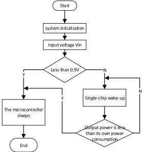
of the solar panel, it will trigger the external interruption of microcontroller in the power management circuit, so the power management circuit began to wake up and work. The basic flow of the power management control software is shown in Figure 2.
!"#$"
%&%"'()*+*"*#,*-#"*.+
/+01")2.,"#3')4*+
5'%%)"6#+)7894
:6')(*;$.;.+"$.,,'$) %,''0%
!*+3,'<;6*0)=#>'<10
?1"01")0.='$)*%),'%%) "6#+)*"%).=+)0.='$)
;.+%1(0"*.+ @+A
B C
C B
Fig. 2. Flow Chart of Power Supply Control Software
4
Experimental data and results of power management circuits
4.1 MPPT experimental data
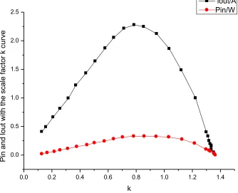
In the MPPT experiment, the solar power management circuit is connected with 4.5V and 3W solar panel input DCDC converter, for measuring the output power Pin of photovoltaic cells and converter output current lout in different proportion factors k, and the curve obtained from the experiment is shown in Figure 3. In the experi-ment, the environmental parameters are light intensity of 45700LUX and temperature of 5 DEG C. According to the curve in Figure 3, it is known that, with the increase of k value, the output power of photovoltaic cell and the output current of converter are both increased first and then decreased, and the maximum value is reached under the same condition of k=0.8 [9]. The experimental data show that the tracking of the maximum output power point (the maximum power point) of the solar panel can be realized by detecting the output current of the converter and by adjusting the k value.
Fig. 3. Curve of Solar Panel Input Power Pin and DCDC Circuit Output Current Lout Chang-ing with k
0.0 0.2 0.4 0.6 0.8 1.0 1.2 1.4
0.0 0.5 1.0 1.5 2.0 2.5
Pin
and
lout
wit
h
the
sc
ale f
ac
tor
k c
urv
e
k
4.2 Charging experimental data
In this paper, a comparative experiment is made on the MPPT charging effects of power management circuit. The experiment uses the same solar panel to charge a lead-acid battery. The charging circuit selects a power management circuit studied in this paper and an integrated solar charging management chip CN3082. The charging chip does not have the function of MPPT. The two, under the same environmental conditions, through the same battery panel, compare the charging current on the same battery, and the experimental data is shown in Figure 4.
Fig. 4.
Contrast Experimental Data between MPPT Charging and CN3082(non-MPPT) Charging
Figure 4 is a comparative experiment of the charging current of lead-acid batteries at about 9 a.m. on May 31, 2017 when the ambient temperature was under the light intensity of 28200LUX, and the temperature was 25V [10-12]. From the curve in Figure, it can be seen that, under the premise of the same environment, the charging current of MPPT tracking charging circuit can reach about 3 times of the charging current of CN3082. It indicates that the charging mode of MPPT tracking can better make full use of the output energy of the solar battery panel, as well as use of solar energy.
0.0 0.5 1.0 1.5 2.0 2.5 3.0
10 20 30 40 50 60 70
rechargi
ng
c
urren
t/mA
Time/min
5
Conclusions
This paper designs a charging and discharging power management circuit of MPPT solar power battery, and the charging efficiency can reach above 80%. The static working circuit of power management circuit is less than 1mA, and it can make intel-ligent dynamic power management in different light intensities, and both stability and reliability of circuit are quite high.
It only focuses on power management circuit of low power (within 5W) solar pow-er panel. If thpow-ere is an opportunity, the design of powpow-er management circuit of high power (10W-500W) solar power panel would be explored. The control algorithm studied here can be easily transplanted into the power management circuit for high-power solar panels. And the solar high-power system with high high-power can be applied in the camera collection in some field work, 4G wireless transmission and other projects.
6
References
[1]Climent, S., Sánchez, A., Blanc, S., Capella, J. V., & Ors, R. (2016). Wireless sensor net-work with energy harvesting: modeling and simulation based on a practical architecture using real radiation levels. Concurrency and Computation: Practice and Experience, 28(6): 1812-1830. https://doi.org/10.1002/cpe.3151
[2]Yoon, I., Kim, H., & Noh, D. K. (2017). Adaptive Data Aggregation and Compression to Improve Energy Utilization in Solar-Powered Wireless Sensor Networks. Sensors, 17(6): 1226. https://doi.org/10.3390/s17061226
[3]Chowdary, G., Singh, A., & Chatterjee, S. (2016). An 18 nA, 87% Efficient Solar, Vibra-tion and RF Energy-Harvesting Power Management System With a Single Shared Induc-tor. IEEE Journal of Solid-State Circuits, 51(10): 2501-2513. https://doi.org/10.1109/ JSSC.2016.2585304
[4]El-Damak, D., & Chandrakasan, A. P. (2016). A 10 nW–1 !W Power Management IC With Integrated Battery Management and Self-Startup for Energy Harvesting Applica-tions. IEEE Journal of Solid-State Circuits, 51(4): 943-954. https://doi.org/10.1109/JSS C.2015.2503350
[5]Hosseinzadeh, M., & Salmasi, F. R. (2016). Determination of maximum solar power under shading and converter faults—a prerequisite for failure-tolerant power management sys-tems. Simulation Modelling Practice and Theory, 62: 14-30. https://doi.org/10.1016/j.sim pat.2016.01.011
[6]Bayrak, Z. U., Bayrak, G., Ozdemir, M. T., Gencoglu, M. T., & Cebeci, M. (2016). A low-cost power management system design for residential hydrogen & solar energy based power plants. International Journal of Hydrogen Energy, 41(29): 12569-12581.
https://doi.org/10.1016/j.ijhydene.2016.01.093
[7]Chen, N., Jung, H. J., Jabbar, H., Sung, T. H., & Wei, T. (2017). A piezoelectric impact-induced vibration cantilever energy harvester from speed bump with a low-power power management circuit. Sensors and Actuators A: Physical, 254: 134-144.
https://doi.org/10.1016/j.sna.2016.12.006
[9]Zessin, H., Spies, P., & Mateu, L. (2016, November). Power density improvement of the power conditioning circuit for combined piezoelectric and electrodynamic generators. In Journal of Physics: Conference Series (Vol. 773, No. 1, p. 012055). IOP Publishing.
https://doi.org/10.1088/1742-6596/773/1/012055
[10]Pukhrem, S., Basu, M., Conlon, M. F., & Sunderland, K. (2017). Enhanced Network Volt-age ManVolt-agement Techniques Under the Proliferation of Rooftop Solar PV Installation in Low-Voltage Distribution Network. IEEE Journal of Emerging and Selected Topics in Power Electronics, 5(2): 681-694. https://doi.org/10.1109/jestpe.2016.2614986.
[11]Guo, K. (2016). Empirical Study on Factors of Student Satisfaction in Higher Education. Revista Iberica de Sistemas e Tecnologias de Informacao, E11: 344-355.
[12]Duan, H.Y. (2016). Research on Collaboration in Innovative Methods of Manufacturing Innovation Chain. Revista Iberica de Sistemas e Tecnologias de Informacao, E11: 292-303.
7
Authors
Jianying Shi is an Associate Professor at Electronic Information Engineering Col-lege, Hebei University, Baoding 071002, China (e-mail: [email protected]).
Yanbin Xu is an Associate Professor at Department of Electrical Engineering, He-bei College of Science and Technology, Baoding 071000, China (e-mail: [email protected]).