A Palmprint Identification System Using Robust
Discriminant Orientation Code
Hoang Thien Van
1, Thai Hoang Le
21
Department of Computer Sciences, Ho Chi Minh City University of Technology, Vietnam
2Department of Computer Sciences, Ho Chi Minh University of Science, Vietnam
Abstract
This paper presents a palmprint recognition system in which we propose a novel acquisition device and a Robust Discriminant Orientation Code, called RDORIC, for palmprint identification. In order to get the clear line features, the device is designed to capture the palmprint images under Green illuminations. To extract RDORIC feature, we present the algorithm which includes two main steps: (1) Palm line orientation map computation and (2) Discriminant feature extraction of the orientation map. In the first step, positive orientation and negative orientation maps are computed by applying the modified finite Radon transform (MFRAT). In the second step, the grid-sampling based 2DLDA, called Grid-LDA, is used to remove redundant information of orientation maps and form a class-separable code more suitable for palmprint identification. The experimental results on the database of our lab and the public database of Hong Kong Polytechnic University (PolyU) show that our technique provides a very robust orientation representation for recognition and demonstrate the feasibility of the proposed system.
© 2014 Published by VNU Journal of Science.
Manuscript communication: received 15 December 2013, revised 13 April 2014, accepted 13 May 2014 Corresponding author: Hoang Thien Van, [email protected]
Keywords: Palmprint identification; Modified Finite Radon Transform; 2DLDA, GridLDA; DORIR.
1. Introduction
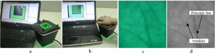
Palmprint is a new kind of biometric feature for personal recognition and has been widely studied due to its merits such as distinctiveness, cost-effectiveness, user friendliness, high accuracy, and so on [1]. Palmprint research employs low resolution images (i.e., less than 150 dpi, see Fig. 1a) for civil and commercial applications. A typical palmprint system consists of five parts: data acquisition device, region of interest (ROI) extraction, feature extraction, matcher and database. The data acquisition device collects palmprint images (see Fig. 1c). ROI extraction sets up a
subspace-based approaches, and fusion approaches. Subspace-based approaches also called appearance-based approaches in literatures use principal component analysis (PCA), linear discriminant analysis (LDA) and independent component analysis (ICA) to project palmprint images from high dimensional space to a lower dimensional feature space [2, 3, 4]. The sub-space coefficients are regarded as features. These approaches were reported to achieve exciting results, but they may be sensitive to illumination, contrast, and position changes in real applications. Line-based approaches will extract palm lines for matching based on using or developing edge detection algorithms [5, 6, 7]. Palm lines are the basic feature of palmprint. However, few principal lines do not contribute strongly enough to obtain a high recognition rate [3]. Therefore, principal lines can be used in palmprint classification [6]. Code-based approaches have been widely investigated in palmprint recognition area due to efficient implementation and high recognition performance. These approaches can obtain the palmprint orientation pattern by applying Gabor filters or MFRAT filters [8, 9, 10]. Fusion approaches utilize many techniques and
integrate different features in order to provide more reliable results [11, 12, 13].
This paper proposes a robust discriminant orientation code, called RDORIC, for palmprint identification system. RDORIC is in low dimensional and discriminant feature space. This idea has been mentioned in our conference paper [15]. In this paper, the palmprint identification system using RDORIC has been developed and much more experiments have been done. The main contributions of this paper consist of the following aspects: (1) A novel method based on the Modified Finite Radon Transform (MFRAT) is proposed for computing two palm line orientation images, called positive orientation feature image and negative orientation feature image, which separately describe the orientation patterns of principle lines and wrinkles. (2) GridLDA is used to project the orientation maps from the high dimensional space to lower dimensional and discriminant spaces. (3) The palmprint identification system, which applying the RDORIC, has been built successfully. The experimental results show that RDORIC is a very robust orientation representation for recognition and demonstrates the feasibility of the proposed system.
HInh 1, hình 2
;
The rest of the paper is organized as follows. Section 2 gives a brief description of our data acquisition device and ROI image extraction. Section 3 presents the proposed robust discriminant orientation code (RDORIC feature). The experimental results are presented in section 4. Finally, the paper conclusions are drawn in section 5.
2. ROI image acquisition
We utilize the palmprint images with 96 dpi resolution to develop a palmprint identification system. In this section, we describe the palmprint acquisition device and ROI extraction method.
2.1. Data acquisition device
Researchers utilize four types of sensors: CCD-based palmprint scanners, digital cameras, digital scanners and video cameras to collect palmprint images [1]. CCD-based palmprint scanners capture high quality palmprint images and align palms accurately because the scanners have pegs for guiding the placement of hands [9, 16]. Although these palmprint scanners can capture high quality images, they are large. Collection approaches based on digital scanners, digital cameras, and video cameras do not use pegs for the placement of hands. Digital scanners are not suitable for real-time application because of the scanning time. Digital and video cameras can be used to collect palmprint images without contact; however these images might cause recognition
problem as their quality is low. We design the novel palmprint capture device which includes webcam web camera, and a light source. Fig. 1a shows the prototype of our device.
The system can capture palmprint image in a resolution of 600 × 480. A user is asked to put his/her palm on the platform (se Fig. 1b). Several pegs serve as control points for the placement of user’s hand. The palmprint image of the palm is collected under Green light because the line features are clearer in Green band than in the others [9].
2.2. ROI image extraction
A region of interest (ROI) will be extracted from the palmprint image for further feature extraction and matching. This can reduce the influence of rotation and translation of the palm. In this paper, the ROI extraction algorithm in [16] is used to find the ROI coordinate system. After ROI extraction, the translation and rotation is usually small between two images. Fig. 1c shows the ROI of palmprint image, and Fig.1d shows the grayscale ROI image.
3. Our proposed RDORIC feature for recognition
The orientation Code is common and robust feature for palmprint recognition such as palmcode [16], competitive code [8], robust line orientation code [10]. However, the orientation code feature is still in large dimensional space
and contains the redundant information. Therefore, we proposed a robust discriminant orientation code for palmprint identification, whose performance is improved by using two strategies. Firstly, a modified finite Radon transform (MFRAT) is applied to extract the orientation feature of principle lines and wrinkles. Secondly, grid sampled based 2DLDA is used to compute the discriminant feature with low dimension.
3.1. MFRAT background [10]
Denoting Zp={0, 1, …, p-1}, where p is a
positive integer, the MFRAT of real function
f[x, y] on the finite grid 2
P
Z is defined as:
[ ]
( )
(,)[ ]
1
, , k
k f i j L
r L MFRAT k f i j
C ∈
= = ∑ (1)
where C is a scalar value to control the scale of
r[Lk], and Lk denotes the set of points that
constitutes a line on the lattice:
(
)
(
)
{
, : 0 0,}
,k p
L = i j j=k i i− + j i∈Z (2)
where (i0, j0) denotes the center point of the
lattice 2
P
Z and k represents the corresponding
slope of Lk. Since gray-levels of pixels on the
palm lines are lower than those of the surrounding pixels, the line orientation
θ
kandthe line energy e of the center point f(i0, j0) of
2
P
Z can be calculated as:
(0,0) arg min
(
k(
[ ]
k)
)
, 1, 2,.., ,k i j r L k N
θ = = (3)
(i0,j0) mink
(
[ ]
k)
, 1, 2,.., ,e = r L k= N (4)
where N is the number of direction in 2
P Z . By this way, directions and energies of all pixels are calculated if the center of lattice 2
P Z
moves over an image pixel by pixel (or pixels by pixels).
3.2. Orientation representation of principle lines and wrinkles
Huang et al. [5] pointed out that the directions of most wrinkles markedly differ from that of the principal lines. For instance, if the direction of the principle lines belong to (0,...,π 2] approximately, the directions of most winkles will be at
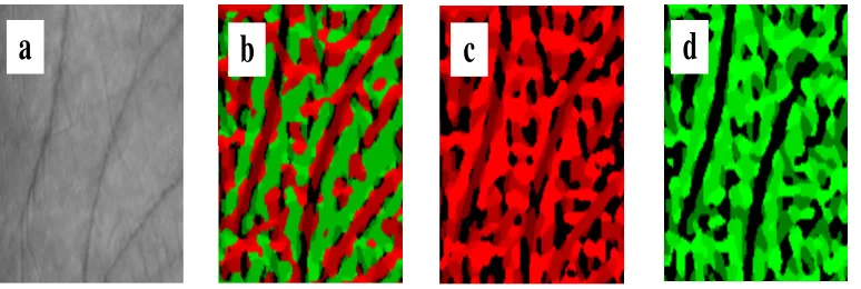
[π 2 ,..., )π . Therefore, we propose a robust orientation representation which separately describes the orientation maps of principle lines and wrinkles. Because the orientation of principle lines can belong to (0,...,π 2] or [π 2 ,..., )π , the orientation representation include two planes of the orientationθ∈[0, ]π : positive orientationθpos,
[0, / 2] pos
θ ∈ π and negative orientaton θneg,
[ /2, ] neg
θ ∈ π π .
F
a
b
c
d
g
The orientations of the center point (i0,j0)
are defined based on MFRAT as follows:
(
)
( )(
(
)
)
(
)
( )(
(
)
)
0 0
0 0 0 0 , 0 0 ,
, arg min , 0,1,2,3
, arg min , 3,4,5,0
p p
p
n n
n
pos k i j k k p
neg k i j k k n
i j r L k
i j r L k
θ θ θ θ = = = = = = (5)
where θpos(θneg) called positive (negative)
orientation because the cosine component of
pos
θ (θneg) is positive (negative). Then, if
orientations of all pixels are computed by equations (1), (2) and (5), two new images, called Positive ORIentation Representation image (PORIR) and Negative ORIentation Representation image (NORIR) are created as:
( ) ( ) ( ) ( ) ( ) ( )
( ) ( ) ( )
( ) { }
1,1 1,2 1,
, 2,1 2,2 2,
,1 ,2 ,
0,1,2,3 , ,
1, , 1,
P P P n
P i j
P P P n
P m P m P m n
k k k
k
k k k
PORIR
i m j n
k k k
∈ = = = M M
L L M L
M (6) ( ) ( ) ( ) ( ) ( ) ( ) ( ) ( ) ( ) ( ) { }
1,1 1,2 1,
, 2,1 2,2 2,
,1 ,2 ,
3,4,5,6 , ,
1, , 1,
N N N n
N i j
N N N n
N m N m N m n
k k k
k
k k k
NORIR
i m j n
k k k
∈ = = = M M
L L M L
M
(7)
Figure 3c and 3d show the PORIR image and the NORIR image, respectively. These two orientation maps are more class-separable than the original orientation map and can be used as the input of GridLDA to obtain projected feature matrix, called Robust Discriminant Orienation Code (RDORIC). Finally, Euclidean
Slide in horizontal direction
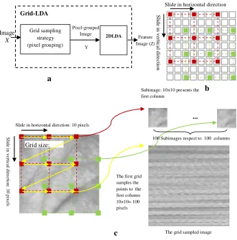
S lid e i n v er tic al d ir ec tio n Grid-LDA Image X Grid sampling strategy (pixel grouping) 2DLDA Pixel-grouped Image Y Feature Image (Z)
a
b
Subimage: 10×10 presents the first column
c
Slide in horizontal direction: 10 pixels
S lid e in v er tic al d ir ec tio n : 1 0 p ix el s Grid size:
The first grid samples the points to the first column: 10×10= 100 pixels
…
100 Subimages respect to 100 columns
The grid sampled image
distance based nearest neighbor classifier is used for recognition. Next subsection presents GridLDA for extracting RDORIC.
3.3. GridLDA background
Grid sampled based 2DLDA, called GridLDA, [13] is the efficient tool for extracting the discriminative and low dimensional feature for classification. GridLDA is 2DLDA with the input which is pixel-grouped images by grid-sampling strategy (see Figure 4a).
The grid-sampling is defined as: a virtual rectangular grid is overlaid on the image matrix (see Figure 4b), and the points at the intersections of gridline are sampled. The sampled pixels are packed into a subset. Then, the overlaid grid slides by one pixel in the horizontal or vertical direction. At each new position, grid-sampling is performed and new subset of random variables is obtained (see Figure 4c). Considering a M0×N0 image, we formulate the strategy as:
( )
{
( )}
( )
(
)
( )
(
)
(
)
( ) ( ) ( )0 0 0 0
0 0
0 0 0
0
0 0
0 0
, , : 0,.., 1; 0,.., 1 ,
, : ; ;
, 0,.., 1; / ;
0,.., 1; /
, , , , ,
, , , , ,
i j i i
g i j
i j o o
RG k p rg x y x k y p
x y x x i k y y j p
rg x y i s s N k
j t t M p
f u v f x y u x k y v i s j x y rg x y rg x y RG k p
= = − = − = + × = + × = = − = = − = = = × + = × + ∈ ∈ (8)
where k and p are numbers of sliding in horizontal and vertical direction respectively;
m=k×p is number of the grid; s and t are width size and height size of the grid respectively;
n=s×t is the number of elements in the grid. Thus, the pixels of each image are grouped into
m sets with the same size (n pixels), called
(
,)
RG k p .
Each set rg x( 0,y0)respects to a column of an m×n pixel-grouped matrix. Figure 4c shows that each grid creates a column of the grid
sampled image which can represent the resized image of the original image, called subimage. Moreover, the subimages are nearly geometrically similar. As the grid sampled image is the input of 2DLDA, 2DLDA can reduce the space dimension effectively because the columns are high correlated. Because these subimages represented for these original images have more discriminative information than that of other sampling strategies (such as: Column, Row, Diagonal, and block sampling strategy), 2DLDA of the grid sampled image can extract the feature which is more discriminative than 2DLDA of all other sampling strategies.
Let’s suppose that there are N training grid sampled images Ai ∈ Rm×n, consisting of L
known pattern classes, denoted as C1, C2, .., CL,
Ci consists of the Ni training images from the ith
class and N=
∑
iK=1Ni. The global centroid A of all training grid sampled image and the local centroid Ai of each class Ci is defined as(
1)
Ni1 iA= N
∑
= A , (1 / )j i
i i A C j
A = N
∑
∈ A . 2DLDAattempts to find a set of optimal discriminating vectors to form a transform X ={ ,x x1 2,..,xd}
defined as:
( )
arg maxX = J X (9)
where the 2D Fisher criterion J X
( )
denoted as:( )
T b T
W
X G X J X
X G X
= (10)
where T denotes the matrix transpose, Gb and
Gw respectively are between-class and
within-class scatter matrices:
(
) (
)
1
1 L
T
B i i i
i
S N A A A A
N =
=
∑
− − (11)(
) (
)
1
1
j i
L T
w j i j i
i A C
S A A A A
N = ⊂
=
∑ ∑
− − (12)The optimal projection matrices
1 2
{ , ,.., d}
orthonormal eigenvectors of 1 w b
G G− corresponding
to the d largest eigenvalues thereby maximizing function J(X). The value of d can be controlled by
setting a threshold as follow:
1 1
d i i n
i i
λ θ λ
= =
≥ ∑
∑ (13)
where λ1,..,λn is the n biggest eigenvalues of
(
)
1w b
G −G and θ is a pre-defined threshold. Let’s suppose that we have obtained the n by d projection matrix X, projecting the m by n grid sampled image A onto X, yielding a m by d feature matrix Y:
.
Y =A X (14)
3.4. RDORIC extraction for classification
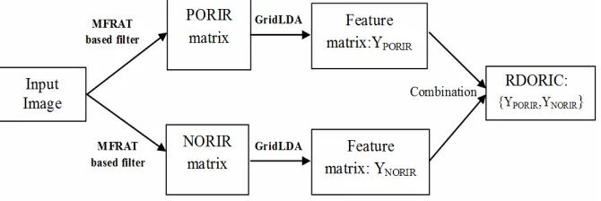
Figure 5 shows an illustration of overall procedure of our proposed method. The processing steps of proposed method for extracting RDORIC feature are summarized as follows:
Step 1: Compute the NORIR and PORIR image of each palmprint image based on
MFRAT based filter by applying equations (1), (2) and (5)
Step 2: Based on GridLDA, compute the RDORIC feature included two matrices YNORIR and YPORIR by applying equation (14) to the NORIR and PORIR image.
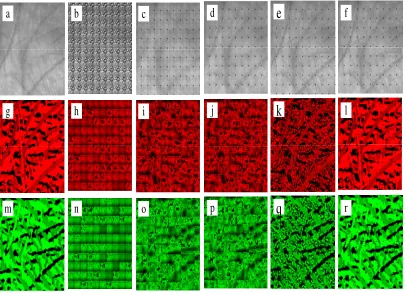
Figure 6 presents some results of our proposed method including: original image, NORIR image, PORIR image and some reconstructed images of these images with different dimension sizes.
Given a sample palmprint image f, use our proposed method to obtain RDORIC feature Y:{YNORIR, YPORIR}, then a nearest neighbor
classifier is used for classification. Here, the distance between Y and Yk is defined by:
( )
( ) ( )
(
)
( ) ( )
(
)
2
, ,
1 1
2
, ,
1 1 ,
1 6
k
k
k k
m d
i j i j
PORIR PORIR i j
m d
i j i j
NORIR NORIR i j
d Y Y Y Y
Y Y
m d
Y Y
= =
= =
= − =
− +
× ×
−
∑ ∑
∑ ∑
(15)
The distance d(Y,Yk) is between 0 and 1.
The distance of the perfect match is 0.
Yw
4. Experimental results
In order to evaluate the proposed method and our system, we compare the identification performance of our method with some state-of-the-art methods on the database of our lab and the public palmprint database of the Hong Kong Polytechnic University, PolyU Multispectral palmprint Databases [14].
4.1. Identification test protocol
In identification, we want to identify which class the query belongs to. Therefore, identification is a process of comparing one query image against all training images and the label of the most similar images is obtained as the identification result.
If a matching score of two images from the same palm is greater than a predefined threshold, the match is a genuine acceptance. Similarly, if a matching score of two images from different palms is greater than a predefined threshold, the match is a false acceptance. Each image in the testing database is matched with all images in the trainning databases to generate incorrect and correct identification scores. The maximum of the distances produced by the query and templates of the same registered palm is considered as correct identification score. Similarly, we take the maximum of the distances produced by the query and all templates of the different registered palms as the incorrect identification score. If the query does not have any registered
a
b
c
d
e
f
g
h
i
j
k
l
m
n
o
p
q
r
Fig. 6. Some samples which demonstrate our feature extraction method: (a) the palmprint image with size 100×100; (b)-(f) some reconstructed images of the original image by GridLDA with d={1,5, 20, 80, 99} respectively; (g) the PORIR image; (m) the NORIR image, and some reconstructed images of the PORIR image (h)-(l) and NORIR image (n)-(r) by GridLDA with d={1,5, 20,
images, we only obtain the incorrect identification score. If we have N queries of registered palms and M queries of unregistered palms, we obtain N correct identification scores and N+M incorrect identification distance. Based on these scores, we obtain the identification results: the receiver operating characteristic curve (ROC curve).
4.2. Experimental results on PolyU Multispectral palmprint Database
Multispectral palmprint database was collected from 250 volunteers, including 195 males and 55 females. The age distribution is from 20 to 60 years old. The samples were collected in two separate sessions. In each session, the subject was asked to provide 6 images for each palm. Therefore, 24 images of each illumination from 2 palms were collected
from each subject. In total, the database contains 6,000 images from 500 different palms for one illumination. The average time interval between the first and the second sessions was about 9 days. In our experiments, we use ROI databases with size 128×128 pixels for evaluate our feature extraction methods. In the following tests, the registration database contains 1500
templates from 250 random different palms, where each palm has six templates. The testing database contains 4500 templates from 250
different registered palms and 250 different unregistered palms. None of palmprint images in the testing database is contained in any of the registration databases. Therefore, we have 1500 correct identification scores and 4500 incorrect identification score. Table 1 presents the parameters of the dataset on which we conduct the experiments.
Table 1. Parameters of databases in identification experiments
Testing set Number of Identification Databases Training set
Registration set Unregistration set Correct distance
Incorrect distance PolyU Multispectral
palmprint [14] (blue set) 250×6=1500 250×6=1500 250×12=3000 1500
1500+3000 =4500 Our database 200×5=1000 200×5=1000 100×5=500 1000 1000+500
=1500
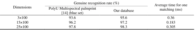
TABLE 2. GENUINE ACCEPTANCE RATE OF OUR PROPOSED METHOD WITH FALSE ACCEPTANCE RATE = 0%
Genuine recognition rate (%) Dimensions PolyU Multispectral palmprint
[14] (blue set) Our database
Average time for one matching (ms)
3×100 93.6 95.6 0.36
15×100 96.2 97.2 0.183
R
Table 2 represents the top recognition accuracy and the corresponding feature dimensions of our method on this dataset. The experimental results present in Fig. 7. Fig. 7a, 7b, and 7c show the correct and incorrect score distributions obtained from Competitive code,
RLOC and our method (RDORIC),
respectively. It can be observed that the distributions of RDORIC are also well separated than that of Competitive Code and RLOC. The Receiving Operating Characteristic
(ROC) curves of Genuine Acceptance Rate (GAR) and False Acceptance Rate (FAR) of RDORIC and others are presented in Fig. 7d. The accuracy of RDORIC is also higher than
that of CompCode and RLOC. Our
experimental results demonstrate that our method is more stable and better than CompCode and RLOC. Fig. 7d shows that our proposed method’s accuracy is about 96.2% GAR with 0% FAR.
R
Fig. 7. Experimental results on PolyU Multispectral palmprint Database: Correct and incorrect identification score distribution of (a) CompCode [8], (b) RLOC [10] and (c) our proposed method with d=15, respectively. (d) The ROC curves for CompCode based
method [8], RLOC [10] and our proposed method with d=15.
a b
E\
4.3. Experimental results on the database of our lab
The palmprint database of our lab contains
3000 samples of 300 different palms. Ten samples from each of these palms are collected in two separated sessions, where 5 samples are captured in each session, respectively. The average time interval between the two sessions is about 15 days. The resolution of these images is 100 × 100 pixels. In the following tests, the registration database contains 1000 templates
from 200 random different palms, where each palm has five templates. The testing database contains 1500 templates from 200 different registered palms (1000 templates) and 100
different unregistered palms (500 templates). None of palmprint images in the testing database is overlapped in registration databases. Therefore, we have 1000 correct identification scores and 1500 incorrect identification scores. Table 1 shows the parameters of the dataset on which we conduct the experiments.
Fig. 8. Experimental results on the database of our lab: Correct and incorrect identification score distribution of (a) CompCode[8], (b) RLOC[10] and (c) our proposed method with d=15, respectively. (d) The ROC curves for CompCode based method [8], RLOC
[10] and our proposed method with d=15.
a b
Table 2 represents the top recognition accuracy and the corresponding feature dimensions of our method on this dataset. Fig. 8a, 8b, and 8c show the correct and incorrect distance scores obtained from palmprint features of Compcode [8], RLOC [10] and our method. It can be observed that the distributions of our method are well separated and a linear classifier would be able to discriminate the genuine and impostor classes. The Receiving Operating Characteristic (ROC) curve of Genuine Acceptance Rate (GAR) and False Acceptance Rate (FAR) of our method and other are presented in Fig. 8d. From this group of figures, we can see that the recognition performance of our method is better than other state-of-art-methods (CompCode [8] and RLOC [10]). Fig. 8d. shows that our proposed method’s accuracy is about 97.2% GAR with 0% FAR on this database.
4.4. Speed
Our proposed method and other methods are implemented using C# on a PC with CPU Intel Core2Duo 1.8 GHz and Windows 7 Professional. The average testing time of the above methods are compared in Table 3. The average execution time for the feature extraction and matching are 65 ms, and 0.13 ms, respectively. The total identification time is about 262 ms with PolyU Multispectral palmprint Database (1500 matching) and 196 ms with the database of our lab (1000 matching).
TABLE 3. COMPARISON OF TESTING TIME
Identification time for one image (ms)
Method
Feature extraction
(ms)
PolyU Multispectral
palmprint Database (1500 matching)
The database
of our lab
(1000 matching) CompCode based
Method [8] 371 583 514
RLOC based
method [10] 62 269 201
Our proposed
method with d=15 65 262 196
5. Conclusion
In this paper, we present a novel palmprint identification system in which we propose a novel data acquisition device and a robust discriminant orientation code (RDORIC) for recognition. The MFRAT is applied to compute the negative orientation representation and positive orientation representation which describe separately the orientations of principal lines and wrinkles. Moreover, it works more quickly than Gabor filter [8, 9]. The output orientation images still contain redundant information in image searching. Threrfore, GridLDA is used to extract the robust discriminant orientation code, called DORIC, which is more suitable for palmprint recognition. Experimental results show that our proposed method outperforms other state-of-art methods (Competitive Code based method [8], and RLOC based method [10]) in terms of higher accuracy and speed on two palmprint datasets (PolyU Multispectral palmprint Database and the database of our lab). Therefore, we conclude that our palmprint identification system can achieve good performance in terms of speed and accuracy.
References
[1] A. Kong, D. Zhang, M. Kamel, “A survey of palmprint recognition”, Pattern Recognition, vol. 42 (2009) 1408.
[2] D. Hu, G. Feng, Z. Zhou, “Two-dimensional locality preserving projections (2DLPP) with its application to palmprint recognition”, PatternRecognition, vol. 40 (2007) 339.
[3] X. Wu, D. Zhang, K. Wang, “Fisherpalms based palmprint recognition”, Pattern Recognition Letters vol. 24 ( 2003) 2829.
[4] G. Lu, D. Zhang, K. Wang, “Palmprint recognition using eigenpalms features”, Pattern Recognition Letters, vol. 24 ( 2003) 1463.
[5] D. S. Huang, W. Jia, D. Zhang, “Palmprint verification based on principal lines”, Pattern Recognition, vol. 41, no. 5 (2008) 1514.
[6] X. Wu, D. Zhang, K. Wang, B. Huang, “Palmprint classification using principal lines”, Pattern Recognition, Vol. 37 (2004) 1987.
Transactions on System, Man, and Cybernetics-part A: Systems and Humans, Vol. 36, no. 5, September (2006) 978.
[8] A.W.K. Kong, D. Zhang, “Competitive coding scheme for palmprint verification”, in: Proceedings of International Conference on Pattern Recognition, 2004. [9] D. Zhang, Z. Guo, G. Lu, L. Zhang, W. Zuo, “An
Online System of Multispectral Palmprint Verification”, IEEE Transactions Instrumentation and Measurement, vol. 59 (2010) 480.
[10]W. Jia, D. S. Huanga, D. Zhang, “Palmprint verification based on robust line orientation code”, Pattern Recognition Vol. 41 (2008) 1316.
[11]F. Du, P.Yu, H. Li, and L. Zhu, “Recognition Using Gabor Feature-Based Bidirectional 2DLDA”, CSEEE 2011, Part II, CCIS 159 (2011) 230.
[12]H. T. Van, P. Q. Tat, T. H. Le, “Palmprint verification using GridPCA for Gabor features”, Proceedings of the Second Symposium on
Information and Communication Technology SOICT'11, 2011.
[13]H. T. Van, T. H. Le, “GridLDA of Gabor Wavelet Features for Palmprint Identification”, SoICT '12 Proceedings of the Third Symposium on Information and Communication Technology, pp. 125-134, 2012. [14]PolyU multispectral palmprint Database, available at
http://www.comp.polyu.edu.hk/~biometrics/ MultispectralPalmprint/msp.htm.
[15]H. T. Van, T. H. Le, "On Discriminant Orientation Extraction Using GridLDA of Line Orientation Maps for Palmprint Identification", Proceedings of the Fifth International Conference KSE 2013, Vol 1 (2013) 237.
![Fig. 7. Experimental results on PolyU Multispectral palmprint Database: Correct and incorrect identification score distribution of (a) CompCode [8], (b) RLOC [10] and (c) our proposed method with d=15, respectively](https://thumb-us.123doks.com/thumbv2/123dok_us/8865899.1810703/10.595.97.490.113.497/experimental-multispectral-palmprint-database-incorrect-identification-distribution-respectively.webp)
![Fig. 8. Experimental results on the database of our lab: Correct and incorrect identification score distribution of (a) CompCode[8],](https://thumb-us.123doks.com/thumbv2/123dok_us/8865899.1810703/11.595.103.497.115.498/experimental-results-database-correct-incorrect-identification-distribution-compcode.webp)
