63
INTERNATIONAL JOURNAL OF ADVANCES IN ENGINEERING RESEARCH
ANALYTICAL STUDY ON BEHAVIOUR OF CONCRETE
STRUCTURAL ELEMENTS SUBJECTED TO IMPACT
LOADING
M.SAKTHIVEL* S.JEYAMURALI** P.KRISHNA KUMAR*, M.HEMA***
*Assistant professor, Department of Civil Engineering, K.C.G College of technology, Chennai, India
** Design Engineer, Megha Engineering Infrastructures ltd, Tuticorin, India.
***Assistant professor, Department of Civil Engineering, Vickram college of Engineering, Madurai, India.
ABSTRACT
The impact loads on structures such as accidental effect from transportation, blasting, gunshots, projectile impact from terrorist attacks can cause a structure to sudden failure. So there is a need of dynamic loading design instead of static loading for the structures to save many lives. The numerical technique is the better economical way than experimental technique to predict the possible failure mode of concrete members subjected to impact loading. The present analytical study is to investigate the behaviour of concrete structural elements subjected to impact loading by using finite element analysis software AUTODYN 12.0.1. The structural elements such as cube, cylinder and beam were modelled and low velocity impact loading was applied to examine the compression, tension and flexural behaviour of concrete elements subjected to impact loading. The damage level was monitored and the Energy absorption capacity (toughness index) of t h e s t r u c t u r a l elements were d e t e r m i n e d and presented.
KEYWORD: Impact load, Energy absorption, low velocity impact load, AUTODYN 12.0.1
1.0 INTRODUCTION
64
INTERNATIONAL JOURNAL OF ADVANCES IN ENGINEERING RESEARCH
of impact test is drop weight hammer impact, which helps to determine the energy absorption capacity (toughness) i.e., E x t e n t to w h i c h a m a t e r i a l absorbs energy without fracture. AUTODYN 12.0.1 is used to simulate the elements subjected to drop weight hammer.
2.0 NUMERICAL MODELLING
The AUTODYN program has much finite element analysis capability ranging from a simple, non-linear explicit dynamic analysis where it Builds the model, Apply loads and obtain the solution and Review the result. Structural analysis is p r o b a b l y the m o s t common application of the finite element method. It is mainly based on four principles. The following are the principles: Lagrange sol vers, Euler solvers, ALE solvers (Arbitrary La gran ge Euler),
SPH solver (Smooth Particle Hydrodynamics) u s i n g these we c a n d e f i n e the m a t e r i a l behaviour, structural behaviour, contact/interaction, fluid structure interaction.
2.1 Lagrange Solver
Lagrangian mechanics is a re-formulation o f classical mechanics using the principle of Stationary action. In Lagrangian mechanics, the trajectory of a system of particles is derived by solving the Lagrange equations in one of two forms, either the Lagrange equations of the first kind or the Lagrange equations of the second kind. It is a combination o f NEWTON, D - ALEMBERTZ, and HAMILTON’S PRINCIPLE. The core element of Lagrangian mechanics is the Lagrangian function, which summarizes the dynamics of the entire system in a very simple expression. Lagrange solvers generally use mesh-based lagrangian methods.
2.2 ANALYSIS OF VARIOUS ELEMENTS USING LAGRANGE SOLVER
All the analysis of the specimen given below are done using AUTODYN.12.0.1.
2.2.1 Analysis of Cube Element
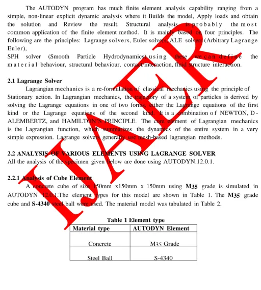
A concrete cube of size 150mm x150mm x 150mm using M35 grade is simulated in AUTODYN 12.0.1.The element types for this model are shown in Table 1. The M35 grade cube and S-4340 steel ball were used. The material model was tabulated in Table 2.
Table 1 Element type
Material type AUTODYN Element
Concrete M35 Grade
65
INTERNATIONAL JOURNAL OF ADVANCES IN ENGINEERING RESEARCH
Table 2 Material Model
Material name Equation of state Strength model
Concrete- 35MPA P-ALPHA RHT CONCRETE
S-4340 LINEAR JOHNSON COOK
The material name is Concrete 35Mpa and equation of state indicates p-alpha (i.e.), p- alpha model to describe the pore compaction hardening effects and thus give a realistic response in the high pressure regime. Strength model is RHT concrete; it is an advanced plasticity model for brittle materials developed by Werner Riedal et al [9]. It is particularly useful for modelling the dynamic loading of concrete.S-4340, the first two digits indicates a 1.8% of Nickel-Chromium-Molybdenum alloy steel the last two digits indicates carbon content roughly 0.4 percent.
2.2.2 Analysis Of Cylinder Element
Cylinder of size 150 mm x 300mm using M35 grade concrete and steel ball of S-4340. Element, Equation of state, Strength model are same as above and it is a 3-D model and the units are mm, ms, mg.
2.2.3 Analysis of Beam Element
Beam of size 500 mm x 100 mm x100 mm using M35 grade concrete and steel ball of S-4340. Element, Equation of state, Strength model are same as above and it is a 3-D
model and the units are mm, ms, mg.
3.0 ANALYTICAL INVESTIGATION
The specimens t hat are used for the analysis are cube element, cylinder element and the Beam element. The Low velocity impact loading was applied by steel ball of S-4340 Element on the concrete models to examine their compression, t e n s i o n and flexural behaviour subjected to impact loading.
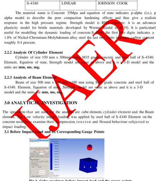
3.1 Before Impact Load and its Corresponding Gauge Points
66
INTERNATIONAL JOURNAL OF ADVANCES IN ENGINEERING RESEARCH
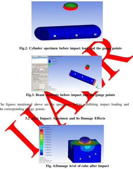
Fig.2. Cylinder specimen before impact load and the gauge points
Fig.3. Beam elements before impact and the gauge points
The figures mentioned above are the specimens before exhibiting impact loading and the corresponding gauge points.
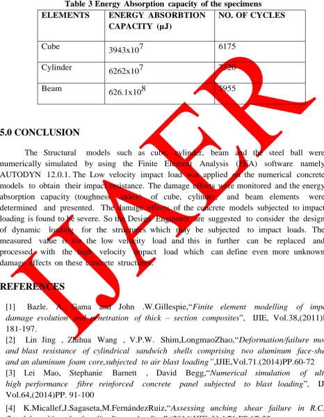
3.2 After Impact: Specimen and its Damage Effects
67
INTERNATIONAL JOURNAL OF ADVANCES IN ENGINEERING RESEARCH
Fig.5.Damage level of cylinder after impact
Fig.6. Damage level of beam after impact
The figures mentioned above are the specimens after exhibiting impact loading and the corresponding damage results.
The given results are based on the principle of LAGRANGE SOLVER
Calculation of energy absorption for cube
Shape of ball = sphere Velocity to
the ball = 300mm/ms Height of fall = 150mm Radius of ball = 30mm
Volume of Sphere (v) = 4/3πr3
= 1.33 x 3.14 x 33 = 113.04 cm3
Mass of ball (m) = density of steel (ƥ) x volume of sphere (v) = 7.83 x 113.04
68
INTERNATIONAL JOURNAL OF ADVANCES IN ENGINEERING RESEARCH
Safety factor = 0.2 Cycle limit = 6175 Time limit = 0.6ms Time increment = 0.05 ms
Calculation of energy absorption capacity for cylinder
Shape of ball = sphere Velocity to the ball = 300mm/ms Height of
fall = 150mm Radius of ball = 35mm Volume of Sphere (v) = 4/3πr3
= 1.33 x 3.14 x 3.53 = 179.50 cm3
Mass of ball (m) = density of steel (ƥ) x volume of sphere (v) = 7.830 x 179.50
= 1405.5 gms (1.40 kg) Interaction gap = 0.2424
Safety factor = 0.2 Cycle limit = 7320
Time limit = 0.738ms Time increment = 0.05 ms
Calculation of energy absorption capacity for beam
Shape of ball = sphere Velocity to the ball = 300mm/ms Height of
fall = 150mm Radius of ball = 35mm Volume of Sphere(v) = 4/3πr3
= 1.33 x 3.14 x 3.53 = 179.50 cm3
Mass of ball (m) = density of steel (ƥ) x volume of sphere (v) = 7.830 x 179.50
= 1405.5 gms (1.40 kg) Interaction gap = 0.2424
69
INTERNATIONAL JOURNAL OF ADVANCES IN ENGINEERING RESEARCH
3.4 RELATIVE GRAPHS: TIME Vs ENERGY ABSORBTION, VELOCITY
Fig.7. Relation between energy absorption capacity and time for cube specimen
Fig.8. Relation between velocity and time
70
INTERNATIONAL JOURNAL OF ADVANCES IN ENGINEERING RESEARCH
Fig.10. Relation between energy absorption capacity and time for cylinder specimen
Fig.11.Relation between energy absorption capacity and time for beam specimen
Fig.12. Relation between time and velocity of gauge points
4.0 RESULTS & DISCUSSION
A dynamic load of 885100mg, 1405500mg was applied at a distance of 150mm from the model elements and corresponding energy absorption capacity was calculated and
71
INTERNATIONAL JOURNAL OF ADVANCES IN ENGINEERING RESEARCH
0.533, 0.6, and 0.738ms respectively. Energy absorption capacity for gauge points was determined and tabulated in Table 3 corresponding to number of cycles.
Table 3 Energy Absorption capacity of the specimens
ELEMENTS ENERGY ABSORBTION
CAPACITY (µJ)
NO. OF CYCLES
Cube 3943x107 6175
Cylinder
6262x107 7320
Beam 626.1x10⁸ 5955
5.0 CONCLUSION
The Structural models such as cube, cylinder, beam and the steel ball were numerically simulated by using the Finite Element Analysis (FEA) software namely AUTODYN 12.0.1. The Low velocity impact load was applied on the numerical concrete models to obtain their impact resistance. The damage effects were monitored and the energy absorption capacity (toughness index) of cube, cylinder, and beam elements were determined and presented. The damage effects of the concrete models subjected to impact loading is found to be severe. So the Design Engineers are suggested to consider the design of dynamic loading for the structures which may be subjected to impact loads. The measured value is for the low velocity load and this in further can be replaced and processed with the high velocity impact load which can define even more unknown damage effects on these concrete structures.
REFERENCES
[1] Bazle. A. Gama and John .W.Gillespie,“Finite element modelling of impact, damage evolution and penetration of thick – section composites”, IJIE, Vol.38,(2011)PP. 181-197.
[2] Lin Jing , Zhihua Wang , V.P.W. Shim,LongmaoZhao,“Deformation/failure modes and blast resistance of cylindrical sandwich shells comprising two aluminum face-sheets and an aluminum foam core,subjected to air blast loading”,IJIE,Vol.71.(2014)PP.60-72 [3] Lei Mao, Stephanie Barnett , David Begg,“Numerical simulation of ultra-high performance fibre reinforced concrete panel subjected to blast loading”, IJIE, Vol.64,(2014)PP. 91-100
72
INTERNATIONAL JOURNAL OF ADVANCES IN ENGINEERING RESEARCH
[5] Ye Yuan, P.J. Tan, “Deformation and failure of rectangular plates subjected to impulsive loadings of zero-period and uniform momentum”,IJIE, Vol.35,(2013)PP. 46-60 [6] A.N.Dancygier, D.Z.Yankelevsky and C.Jaegermann, “Response of high
performance concrete plates to impact on non-deforming projectiles”,IJIE,Vol.34,(2007)PP.1768-1779
[7] X.X.Zhang, G.Ruiz, R.C.Yu, “Fracture behaviour of steel fibre reinforced concrete at a wide range of loading rates”, IJIE, Vol.71,(2014) PP.89-96
[8] JuechunXu , Chengqing Wu , Zhong-Xian Li“Analysis of direct shear failure mode for RC slabs under external explosive loading”, IJIE, Vol. 69,(2014) PP. 136-14
[9] Werner Riedel, Nobuaki Kawai, Ken-Ichi Kondo,“Numerical assessment for impact strength measurements in concrete materials”, IJIE,Vol.36,(2009)PP.283-293.