INTRODUCTION
Cities and development projects that include green space and common areas in which people can interact are more beautiful, livable, safe and desirable to businesses, tourists and residents. However, attracting people to these urban areas means attracting and parking their cars.
Numerous research studies (by MIT, Trans-portation Alternatives and others) state that 30 % to 50% of traffic congestion in city centers is gen-erated by drivers searching for a parking space. A lack of sufficient downtown parking is often due to the large space required for conventional ramp parking [8].
Automatic parking systems [5, 6] are relatively complex technologies with a computer-controlled
automated vehicle loading and unloading process using a highly-advanced technology.
Company see [6] possesses the capacity and technical knowledge to handle the entire pro-cess, including the technical specifications for installation, in the most cost-efficient and effec-tive way possible. All of this has allowed for the construction of highly prestigious public and pri-vate parking facilities in many parts of the world. PARKPIÚ’s extensive experience in the industry has allowed for the development of products and systems able to solve the most varied of problems encountered in the realization of mechanized parking facilities.
Maximizing space is critical for architects and developers particularly on a small site. If too much space is consumed by parking requirements,
Forces Generated in the Parking Brake of the Pallet Locking System
Leopold Hrabovský
1*, Tomáš Mlčák
2, Gustav Kotajný
31 VSB Technical University of Ostrava, Faculty of Mechanical Engineering, Institut of Transport, 17. listopadu
2172/15, 708 00 Ostrava – Poruba, Czech Republic
2 VSB Technical University of Ostrava, Faculty of Electrical Engineering and Computer Science, Department of
Electrical Engineering, 17. listopadu 2172/15, 708 00 Ostrava – Poruba, Czech Republic
3 KOMA – Industry s.r.o., Ruská 514/41, 706 02 Ostrava – Vítkovice, Czech Republic
* Corresponding author´s e-mail: [email protected]
ABSTRACT
Automatic parking systems are parking structures with a computer-controlled automated vehicle loading and un-loading process using sophisticated technological equipment. The paper describes a construction design for a pallet locking system, which is used to lock parking pallets with or without a vehicle, at a particular location and
floor, that is, in a rack cell. This is one of the basic design concept variants of “Multi-Tower” automatic parking
systems. This concept makes it possible to store cars stacked in rack cells. Cars on pallets are guided to the verti-cal cells of the parking system, stacked above each other on pallets, by an electric freight traction elevator. Pallets
are stacked into the horizontal cells, on either or both sides, on a given floor of the parking system by means of a chain transfer device. After the pallet has been guided to a particular position, the pallet must be fixed in this
position by the pallet locking system so that when the vehicle needs to be retrieved, the chain transfer device can again latch onto it and move it to the traction lift cage without any problems. The locking system also functions as a brake for the pallet carrying the parked vehicle. The paper also presents the theoretical calculations of the pallet
brake, which is a crucial element of the pallet locking system of the conceptual variant of the “MULTI TOWER”
automatic parking system.
Keywords: automated parking system, locking system, pallet brake.
Volume 13, Issue 4, December 2019, pages 181–187
https://doi.org/10.12913/22998624/111478
Research Journal
Accepted: 2019.10.15rapid throughout (the number of cars in and out per hour) and a satisfying user experience.
Architects and developers regularly have to compromise design or reduce saleable space to accommodate required parking. Sometimes, the large amount of land area required for parking makes the entire project nonviable. The design concept variants [1] of automatic parking sys-tems offer a safe and intelligent way of collective short-term and long-term (subscriber) car parking on the principle of a handling and storage model.
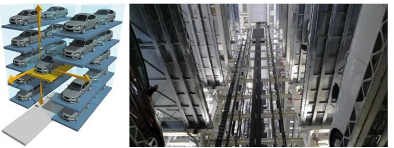
They are designed especially for parking of passenger cars but can also be used for parking of vans or trucks. They address situations with a lack of parking spaces and a lack of free space for the implementation of standard surface park-ing, especially in housing estates, in the centers of large cities, in administrative units, hotels, air-ports, railway stations and P&R type parking lots. The design variant of the “MULTI TOWER” automatic parking system [1] stores cars on pal-lets in cells stacked above each other, as shown in Figure 1. After inserting a pallet in a specific rack cell on one side or the other of a given floor of the automated parking system, the pallet must be se-cured in a strictly determined position. The pallet fixing is ensured by a locking system consisting of two basic construction components, the “pallet brake” and the “brake catch”.
The bodies of the pallet brakes 1, see Fig. 4, of the pallet locking system, are fastened to the lower steel beams of the rack cells by bolted con-nections, see Figure 3.
Bearings 14, see Figure 4, are connected the pulley holder 2 by a pin 5. The distance of the bearings 14 from the recessed surface in the brake body 1 is delimited by the length of the compres-sion coil spring 16.
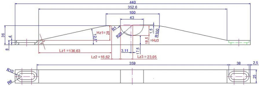
At a certain point when the pallet is inserted into the rack cell, moving at a speed vp = vr [m. s-1], and reaches a certain position, the bearings of
the brake 14 begin to roll along the beveled part of the brake track, see Figure 2. In time tz1 [s], see relationship (1), when the bearings 14 roll on the beveled part of the brake track, the coiled cy-lindrical spring 16 is gradually compressed. The compressible cylindrical spring, 16 V16–102; see [2], with a rectangular wire b x h = 3.2 x 1.5 mm, free length L0 = 102 mm, external diameter DH = 16 mm and internal diameter Dd = 8 mm; increases in stiffness kp = 7.8 N/mm.
In time tz1 [s], i.e., in the time, in which the brake bearings 14 roll away along the beveled part of the brake track, the pallet moves in a hori-zontal direction by a length of Lz1 = 136.63 mm, see Figure 2.
z1 z1 p
t = L / v [s]
(1)After the elapsing of time tz1 [s] the spring 16 compresses by a value of Hz1 = 28 mm, see Figure 2. At a compression of the spring of Hz1 [mm] the spring 16 exerts a pushing force Fp1 [N] see relationship (2a).
p1 z1 p
F = H . k = 28. 7,8 = 218,4 N
(2a)On Figure 4, item 3 indicates the adjusting bolt. The adjusting bolt 3 makes it possible to change the initial spring pressure 16 by a maxi-mum value of Hz = 13 mm.
At the maximum initial compression of the spring Hz [mm] and after the elapse of the time tz1 [s], where the spring 16 was compressed by the value Hz1 [mm] the spring 16 would generate a pushing force of Fp1 [N] see relationship (2b).
p1 z z1 p
F = (H + H ). k =
= (13 + 28). 7,8 = 319,8 N
(2b)In the subsequent text of the paper, the re-lationships will take into consideration the case where the initial spring compression Hz [mm] is
equal to zero, that is, the adjusting bolt 3 does not exert any initial deformation of the spring 16.
In time tz2 [s], i.e., in the time, when the brake bearings 14 roll away along the beveled upper surface of the non-angled section of the brake track, the pallet moves in a horizontal direction by a distance of Lz2 = 16.62 mm, see Figure 2.
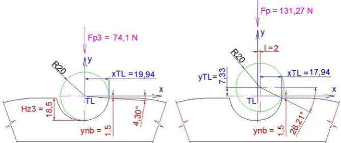
In time tz3 [s], i.e., in the time, during which the outer surfaces of the brake bearings 14 begin to make contact with the right inner surface of the recessed sector of the brake track, the pallet has shifted in a horizontal direction by a value of Hz1 – Hz3 = 28 – 18.5 = 9.5 mm, see Figure 2. Upon compression of the spring Hz1 – Hz3 [mm] the spring 16 exerts a pushing force of Fp3 [N] see relationship (3).
(
)
(
)
p3 z1 z3 p
F = H - H . k =
= 28 - 18,5 . 7,8 = 74,1 N
(3)When the exterior surfaces of the pallet brake bearings 14 contact the lower surface of the milled recess in the form of a circular segment Fig. 2. Brake track of the pallet locking system of the “MULTI TOWER” design for an automatic parking system
in the brake start, the pallet with the vehicle is in the “parking position”. In the parking position, the horizontal pulling force exerted by the chains of the chain conveyor no longer acts on the pallet. The vehicle pallet is locked in the parking posi-tion by the pressure force Fp3 [N] of the reshaped spring 14, whose length Lp [mm] is indicated by the relationship (4).
p 0 z1 z3
L = L - H + H =
= 102 - 28 + 18,5 = 92,5 mm
(4)SHUTDOWN OF ACTIVITY
OF LOCKING SYSTEM
In order to move a pallet in the parking posi-tion in the horizontal direcposi-tion by a length of l = 2 mm, it is necessary to apply a force F [N] to the pallet in the horizontal direction, see Figure 6.
The vertical displacement of the bearing axis 14 (held in the pulley holder 2 of the locking sys-tem) by the length l = 2 mm, exerted by the acting
force Fx [N] in the bearing axis 14, results in a vertical displacement of the bearing axis 14 by yTL = 7.33 mm, which causes a deformation of the cylindrical compression spring 14.
At this time (the vertical shifting of the bear-ing axis 14 by a value of l = 2 mm), it is possible, using Figure 5.b and Figure 6, to set the compres-sion sp2 [mm] of the coiled spring 16 according to relationship (5).
p2 z1 z3 TL
s = H - H + y =
= 28 - 18,5 + 7,33 = 16,83 mm
(5)Compression sp2 [mm] of the coiled spring 16 causes the magnitude of the pushing force Fp2 [N] in the spring 16, see relationship (6).
p2 p2 p
F = s . k = 16,83. 7,8 = 131,27 N
(6) The required magnitude of the force Fx(l) [N] on the axis of the bearings 14 of the locking sys-tem, which causes a vertical movement of the axis of the bearings 14 by a magnitude of yTL(l) [mm], can be expressed according to Figure 6 and the equation (8).Fig. 4. Design variant No. 2 of the pallet brake of the pallet locking system
The sum equation of acting forces in the “y” axis direction, according to Figure 6, is shown by the relationship (7).
y p(l) y(l)
p(l) y(l)
F = 0: F - F = 0
F = F [N]
⇒
⇒
∑
(7)sL x(l) Fx(l) y(l) TL(l)
x(l) TL(l) nb y(l) TL(l)
y(l) TL(l)
x(l)
TL(l) nb
M = 0: F . y - F . x
= 0
F . (y
+ y ) - F . x
= 0
F . x
F =
[N]
y
+ y
⇒
⇒
⇒
⇒
∑
(8)
Where
nb TL(l)
(l)
Fx(l)
y + y
= arcsin =
R y
= arcsin [deg] R
TL(l) (l)
x = R. cos [m] .
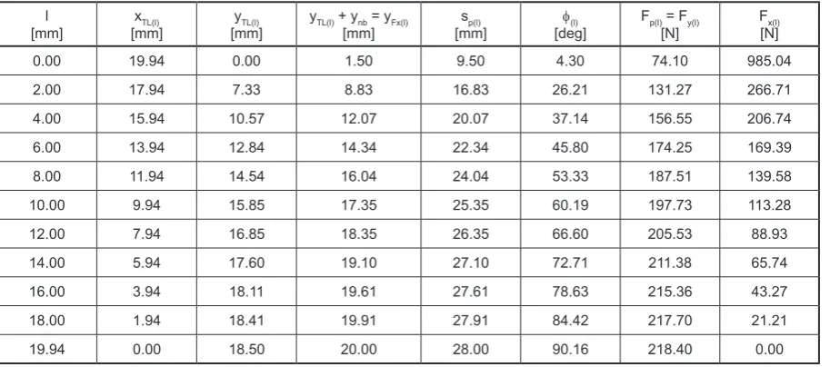
In Table 1 and on Figure 7, the vertical move-ment values yTL(l) [mm] of the bearing axes are
shown, along with the compression of the coiled spring 16 and the angle f(l) [deg] depending on the horizontal l [mm] shifting of the bearing axis 14.
Vertical displacement of the pulley axis, coil spring compression, angle f(l) [deg] depending on horizontal displacement of the pulley axis. The Figure 8 shows the acting horizontal force Fx(l) [N] in the bearing axis 14 and the compressive force Fy(l) [N] produced by the spring 16 of the locking system in dependence on the horizontal l [mm] displacement of the bearing axis 14.
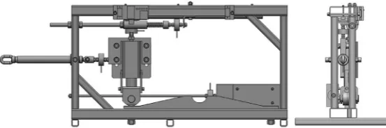
Device for testing the pallet locking brake system
A device has been prepared for experimental verification of the theoretically determined forc-es Fx(l) [N] and Fy(l) [N], when guiding the pallet brake into the recess in the brake track of the pal-let locking system. A 3D model of experimental device shown in Figure 9.
The device makes it possible to attach one or the other design to a special bracket (not described Fig. 6. The bearing pulley moved in the horizontal direction from the
recess in the shape of a circular cut-out of the brake track
in more detail in this paper) of the pallet locking brake, which is then allowed to move vertically thanks to the rotation of the screw of the screw spindle [4], the nut of which is attached to the ver-tical beams of the frame structure. The pressure force Fx(l) [N] generated by the rotating screw of the screw spindle is detected by the tensometric force sensor and its progress over time (during the rolling of the bearings of the locking brake along the selected brake track) is recorded by the mea-suring apparatus.
Due to the design of the locking brake, the spring 16 in the brake housing 1 is compressed during the rolling of the bearings 14 mounted in the brake bearing bracket 2 along the angled and the straight part of the brake ramp. The brake body bracket is also connected to the upper frame beams by a tensometric strain gauge. The vertical force Fy(l) [N], which is directly proportional to
the magnitude of the compressive force exerted by the deformation of the coil spring 16, is detect-ed and recorddetect-ed by the force sensor horizontally moving over the upper surface of the brake ramp.
SolidWorks
Both pallet brake system designs (one is shown in Figure 3) of the “MULTI TOWER” automatic pallet parking system, as well as com-ponent parts of the construction design of the ex-perimental equipment, will be described in detail in the subsequent paper.
The experimental values and measured wave-forms Fx(l) [N] a Fy(l) [N] will also be evaluated in the upcoming paper and these will be verified with theoretical values of horizontal Fx(l) [N] and the vertical forces Fy(l) [N] shown in Table 1 and Figure 8.
Fig. 8. Horizontal force in the axis of the pulley, vertical force exerted by the spring depending on the horizontal displacement of the pulley axis
CONCLUSION
The automatic parking system, after lifting the pallet with the vehicle to the floor designated by the control system, moves the pallet using a chain conveyor to the taxiway in the parking box provided with plastic rollers. Achievement of the correct parking position is identified by sensors located on each floor. At this point, the controlled drive of the chain conveyor is switched off and the pallet should be locked by two mechanical brakes.
In many cases, when loading pallets with ve-hicles into parking boxes on sub-floors, pallets fail to reach or exceed the correct parking posi-tion. Failure to reach the correct parking position is due to the non-insertion of the locking brake pulley into the recess in the form of a circular cut-out of the brake track on the attached pallet. Exceeding the correct parking position is caused by the pallet being “over-pulled” during insertion, and thus the locking brake pulley being pushed out of the recess in the shape of a circular cut-out sector of the brake track on the pallet.
It is presented that the weakest link in the reli-ability of the automatic parking system is the pal-let locking device, which is presented as a palpal-let brake. In terms of mechanical principle, this is not a real brake, but a locking mechanism with a spring and a rotary pulley which, in addition to locking the pallet in the parking position, is able to partially brake and stop the pallet.
The purpose of the paper was to determine the actual theoretically acting forces and kinematic ratios in play during the guiding / pushing of the locking brake pulley into/out of the recess in the form of a circular cut-out sector of the brake mounted on the pallet. These theoretical conclu-sions will now be verified on a model device where the actual forces applied to guide the pallet to the correct parking position will be experimen-tally obtained. The applied force values obtained will be used to modify the software that controls the speed of the chain conveyor drive and thus the
speed of the chain movements so as to achieve, as accurately as possible, the guiding of the brake pulley into the recess in the pallet brake track and thus the exact parking position of the pallets loaded with vehicles for the automated “MULTI TOWER” parking system.
Acknowledgements
This work has been supported by The Ministry of Education, Youth and Sports of the Czech Republic from the Specific Research Project SP2019/101 and a Contract for work No. S40/19–342–01.
REFERENCES
1. KOMA, 2019, http://komaparking.cz/parkovaci-systemy/
2. SpecialSprings, 2019, http://specialsprin gs.com/en 3. Hrabovský, L., Mantič, M., Voštová, V., Adhesion
Coefficient on the Limit of Slippage at Star-Up of
the Manual Crane Trolley. Advances in Science and Technology Research Journal, 2, May 2019, 92–99. DOI: 10.12913/22998624/106244.
4. Hrabovský, L., Apparatus Producing an Even Dis-tribution of Strain into Carries. World Multidis-ciplinary Civil Engi-neering – Architecture – Ur-ban Planning Symposium, 245, 2017, 1–6. DOI: 10.1088/1757–899X/245/2/022097.
5. GDMUTRADE, 2018, www.qdmutrade.com/ nav/27.html
6. PARKPIU, 2019, https://www.parkpiu. com/ 7. Robotic Parking Systems, 2019,
https://www.ro-boticparking.com/roboticparking_rps_100.htm 8. Hrabovský, L., Maslarić M.: Device designed
for detection and setting the required tensile force in ropes. Advances in Science and Tech-nology Research Journal, 12(1), 2018, 200–206, DOI: 10.12913/22998624/86614.
![Figure 8 shows the acting horizontal force Fx(l) [N] in the bearing axis 14 and the compressive](https://thumb-us.123doks.com/thumbv2/123dok_us/8804933.1774057/5.595.70.290.314.536/figure-shows-acting-horizontal-force-bearing-axis-compressive.webp)