INTRODUCTION
The possibilities of new products design pro-cess implementation are changing with the rapid development of the computer technology. It is the process of software environment simulation of the equipment being developed that has become an es-sential and very powerful tool for handling even the most complex problems of the engineering practice.
The initial proposal and more accurate design of new equipment made in the simulation process save time as well as provide financial gains. Sav -ings are also shown in the performance of the ex-periment itself, because the very exex-periment can be prepared with minimum weaknesses thanks to the simulation [3].
A structure created using the synthesis meth-od has a great advantage in the opportunity to as-sess the shape, form, appropriateness and func-tionality of the technical equipment design.
Another reason why the simulation and anal-ysis are a necessity is the assessment of the suit-ability of proposed materials in terms of strength as well as material properties and behaviour, which has a direct impact on the equipment func-tionality and safe operation [4].
In this paper, we presented a simulation of a new design of technical equipment, which
would lead to verification of its functionality in terms of the kinematic, dynamic and strength parameters [9].
DYNAMIC ANALYSIS OF A LOCKING
MECHANISM VIRTUAL PROTOTYPE
A seat in the car supports, positions and protects a passenger. In order for the ride to be comfortable, ergonomic and safe at the same time, the car interior elements must be modified or adjusted to suit the widest possible range of passengers. One of the most important modifications of the car interior is the distance of the seat from the steering wheel. On the ba-sis of these facts it is necessary to adapt the seat individually and enable its adjustment ac-cording to the size and needs of the passenger. Quick and safe securing of the distance of the seat from the steering wheel is provided by a locking mechanism that attaches the seat to the car floor.
Ideally, the car seat position adjustment should be possible to change within the short-est time possible. At the same time, this process should take place as smoothly as possible, and with maximum safety for the passenger. The Volume 13, Issue 1, March 2019, pages 23–28
https://doi.org/10.12913/22998624/101601
Dynamic and Stress Analysis of a Locking Mechanism in the
Ansys Workbench Software Environment
Alžbeta Sapietová
1*, Pavol Novák
1, Milan Sága
1, Peter Šulka
1, Milan Sapieta
11 University of Žilina, Faculty of Mechanical Engineering, Univerzitna 1, 01026 Žilina, Slovakia
* Corresponding author’s e-mail: alž[email protected]
ABSTRACT
This paper presents dynamic and stress analysis of a virtual prototype (VP) of a lock mechanism, which would lead
to verification of its functionality in terms of kinematic, dynamic and strength parameters. The proposed modifica
-tions of input parameters of the technical equipment addressed were verified using the software environment of MSC. ADAMS and FEM software ANSYS Workbench.
Keywords: simulation, sensitivity analysis, dynamic analysis, stress analysis, MSC.ADAMS, ANSYS.
Research Journal
Accepted: 2019.02.12locking mechanism portfolio comprises a number of design types, for example vertical or horizontal ratchet or permanent engaged locking.
This paper presents an analysis of a virtual prototype (VP) mechanism of a modular lock that is used to lock, or prevent the movement of the car seat sliding rails in the direction of the vehicle travel.
MOBILITY OF THE LOCK MECHANICAL
SYSTEM
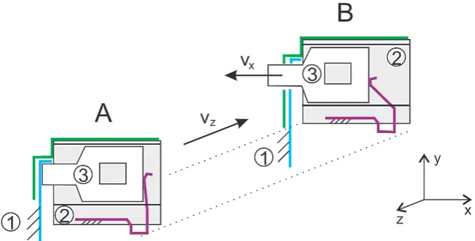
Figure 1 shows a kinematic diagram of the locking mechanism. This scheme includes only those structural elements which have a decisive influence on the results of dynamic and stress analysis. The elements are: frame (1), housing that includes the upper rail (UR) (2), locking element (LP1/LP2) (3). Scheme A shows the state while turning the locking rod unlocks the seat and the locking elements lean upon the side of the lower (blue) rail. The seat travels along the lower rail at the velocity vz from position A to the position where there is an opening. Subsequently, a pre-stressed leaf spring enables insertion of the lock-ing element into the openlock-ing at the velocity vx.
This kinematic system has two degrees of freedom n. The first degree of freedom is defined by the upper rail moving on the lower rail, and the second degree of freedom is the movement of the locking element to be inserted into the opening using the pre-stressed spring. During the dynamic analysis in the MSC.ADAMS environment, we considered two moving bodies in a three dimen-sional space. Then, the equation for calculating
the constrained mechanical system degrees takes the following form:
(1)
where: u – the total number of members in the constrained mechanical system, including the frame,
nv(u-1) – mobility of a group of free
bodies,
– removed degrees of free-dom due to constraints between pairs of members of the constrained mechanical system.
That between pairs of members of the con-strained mechanical system is provided by the equation:
where: st – the number of links of class t of all
pairs of constrained bodies in the con-strained mechanical system,
stv – the number of links of class t linking
the number v of members,
v – the number of bodies in the link st of
bodies,
vm – the maximum number of bodies
links of class t in the constrained mechan-ical system.
Two situations may occur during locking: a partial lockdown, i.e. the locking element passes through only one opening in the upper rail, and a complete lockdown of the mechanism when the locking element passes through both openings in the upper rail (Fig. 1B).
INPUT PARAMETERS
It should be noted that if the modular lock is unlocked even during a ride, a sudden decel-eration / acceldecel-eration occurs, then the locking elements might not bog down into either of the openings in the lower rail (LR). This would pre-vent locking the car seat and it would move all the way to the improper extreme position, i.e. to the dash board.
The task of dynamic analysis in MSC.AD -AMS software was to verify whether the modular lock is able to provide and ensure sufficiently safe locking of the moving car seat even at maximum deceleration / acceleration values. The accelera-tion parameter was obtained from the data mea-sured in a crash test.
A 3D model of the locking lock mechanism was created in Catia software. Individual VP files were imported in .stl format to the MSC.ADAMS/ View environment. The bodies were considered as rigid (Rigid Bodies). The VP model used shift -ing geometric constraints and contact function.
The total VP mechanism weight was calcu-lated as the sum of the child dummy weight (22 kg), child safety seat weight (8 kg) and the car seat itself (20 kg). Since the car seat is screwed to the two rails and each rail has its own modu-lar lock, the calculated total weight was divided equally between the two rails.
In order to carry out VP simulation, we recom-mended the acceleration of 25.25 g m/s2. This
pa-rameter was obtained during an actual crash test. A real spring is represented in the VP by a geometric constraint (SPRING). The spring was connected to the housing in the marker located at the height of the centre of gravity LP1/LP2, and to the marker of the locking element’s centre of gravity LP1/LP2. Monitoring the current position of LP1 and LP2 in the rail opening was carried
out using marker distance meter [5]. One meter was on the LP1 and LP2 edge, while the other, reference meter, was situated on the edge of the upper rail outer opening (Fig. 2).
In geometric constraints, we considered pas-sive resistances in order to achieve simulations displaying more accurately the real mechanism behaviour.
SIMULATION CONSIDERING THE
SYSTEMS CONCURRENT MOTIONS
While solving the proper functioning of the locking mechanism in the MSC.ADAMS software environment we carried out several sensitivity anal-yses, the outcome of which were specification of the force effect range in the mechanism’s spring, structural modification of LP1/LP2, and passive resistances in geometric constraints [6]. Then, con-sidered only those parameters that have the greatest influence on the proper functioning of the equip -ment, and carried out a simulation with consider-ation of the system´s concurrent motions [1].
Next, we present a simulation in which the lower rail carries the upper rail at a constant ve-locity. The lower rail then abruptly stops and up-per rail moves further due to inertial effects. Dur -ing this event it is necessary that LP1 and LP2 fit into the lower rail openings, which would confirm proper functioning of the locking mechanism.
The constant velocity value was chosen as 11.19 m/s. In order to ensure that the upper rail, upon the lower rail abrupt stopping, continues with acceleration 25.25 g m/s2, the lower rail had to gain
zero velocity within 0.0451s. When we consider constant acceleration, the following applies:
(2)
Thus, the rails moved relative to each other by more than 6 mm; hence, two events could occur: insertion of LP1/LP2 into the rail openings, and the subsequent locking of the mechanism. The simulation in MSC.ADAMS was controlled by STEP function:
STEP (time, 0, 0, 30, 11 190) +
STEP (time, 31, 0, 31.0451, -11 190).
We carried out a significant number of simu -lations with varying loads applied by the springs onto LP1/LP2. The best results in terms of the equipment functionality were achieved with the load from the spring forces 20 N and 25 N.
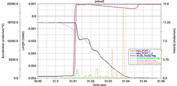
The curve in Figure 3 shows the relative posi -tion of the locking elements marker and the refer-ence marker on the rail at the spring force of 25N. The Figure 3 shows that the two locking el -ements engaged in full lockdown, where LP2 re-mained in the full lockdown and LP1 slid by 0.5 mm, while it remained in the fully locked position. This phenomenon was caused by an abrupt im-pact of the lower rail onto LP1. Figure 4 shows the positions of LP1/LP2, velocities and accelerations of the upper and lower rails according to time. Here it should be noted that the peaks seen in acceleration in all scenarios were caused by the impact forces in contact after LP clicking, and their value was affect -ed by the fact it was a contact of rigid bodies.
EXPLICIT DYNAMIC ANALYSIS OF THE
LOCKING MECHANISM IN THE ANSYS
WORKBENCH SOFTWARE ENVIROMENT
Explicit dynamic analysis in the ANSYS Workbench software environment was conducted to determine the stress-deformation and
kine-matic behaviour of the mechanism with consid-eration of elastic-plastic behaviour of individual parts of the mechanism [2, 8]. This type of analy-sis is characterised by very small time increments [7]. The task initial conditions were defined by complete locking of the two LP1/LP2, the upper rail had an initial velocity of 11.19ms-1, and
con-tact forces of 25N were applied on the two LP1/ LP2 by the spring in the x axis direction (Fig. 1). The lower rail was anchored to the frame. The beads between the upper and lower rails to en-able relative sliding movement were not mod-elled. Their effect was modelled by removing the lateral displacement on the rail surfaces touched by the beads. We modelled a contact with fric -tion between the mechanism bodies (except for the lower rail). The unlocking rod was fixed in its position by rough contact. Solving was executed for the time interval 0 to 2.63.10-5 s.
The material data of individual mechanism elements were obtained from the Workbench soft -ware material database. These materials included structural steel (LP1), Steel 4340 (rails, LP2, un -locking lever) and Polycarb2 (housing).
Fig. 3. Position of LPI1 and LP2 relative to the lower rail (25N-mod.geom.)
We carried out two analyses to determine the impact of the LP1 material properties choice on the stress and deformation on the mechanism.
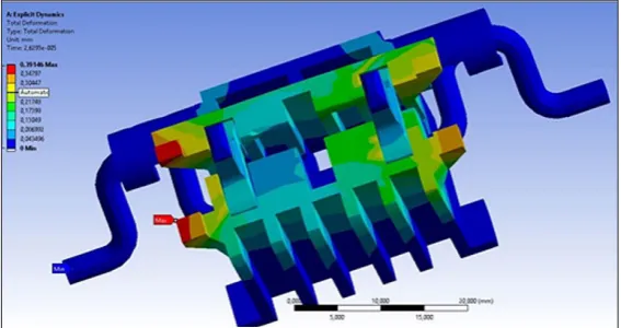
The first analysis used LP1 as the material, i.e. structural steel with linear material behaviour. For LP2, we used Steel 4340 with nonlinear material behaviour. The second analysis used Steel 4340 for the two LP1/LP2. Figure 5 shows the course of the overall displacements on the housing, LP1 and LP2, and unlocking rod at the time of the two LP1/ LP2 impacting the end of the lower rail grooves.
Figure 6 shows the course of von Mises stress in LP1 and LP2 for the first analysis, for which we used a linear material model on LP1. In this case, von Mises stress on LP1 reaches the val-ue of 1588MPa, valval-ues for LP2 are significantly lower – around 830 MPa.
Figure 7 shows the course of von Mises stress on LP1 and LP2 for the second analysis – the material chosen for the two LP1/LP2 was Steel 4340. We can observe a significant reduction of maximum stress to the value of 970MPa.
Fig. 7. Von Mises stress on LP1 and LP2 for the second analysis
Fig. 5. Overall displacements on he mechanism elements (without rails)
CONCLUSIONS
Dynamic simulations in MSC.ADAMS con -firmed that:
1. The locking mechanism fulfils its function in terms of full lockdown, when a boundary con-dition of acceleration is defined.
2. It is necessary to consider the load from leaf springs because, based on the results of dy-namic simulations, the spring force value of 10N as proposed by the manufacturer is insuf -ficient for safe lockdown of the mechanism.
The stress and dynamic analyses carried out in ANSYS Workbench confirmed that the stress did not exceed the allowable limit of the ultimate strength in either of its members. The mecha-nism design complies with the dynamic load.
Acknowledgement
This work was supported by the Slovak Grant Agency VEGA 1/0795/16 and VEGA 1/0234/13.
REFERENCES
1. Arnold M., Schiehlen W. 2008. Simulation Tech
-niques for Applied Dynamics. CISM Courses and Lectures, Springer Wien: New York , Vol.
507, pp. 313.
2. Dekys V., Kopas P., Sapieta M., Stevka O. 2014. A
detection of deformation mechanisms using infra-red thermography and acoustic emission. Applied Mechanics and Materials, Vol. 474, 315-320. 3. Stancekova D., Semcer J., Derbas M., Kurnava T.
2013. Methods of measuring of residual stresses and evaluation of residual state of functional
sur-faces by x-ray diffractometric methods. J. Manu -fact. Technol., 13(4), 547-552.
4. Mocilan M., Zmindak M., Pastorek P. 2016. Dy
-namic analysis of fuel tank. Procedia Engineering,
Vol. 136, 45-49.
5. Palcak F., Hok V. 2007. Reasons for appliation of Newton-rapson iteration method for determination
of dependet position soordinates time course in the mechanisms. 6th Int. Conf. APLIMAT 2007, 101-109.
6. Sapietova A., Saga M., Novak P., Bednar R, Dizo J. 2011. Design and application of multi-software
platform for solving of mechanical multi-body sys-tem problems. Mechatronics: recent technological
and scientific advances, 345-354.
7. Vasko M., Guran A., Jakubovicova L., Kopas P. 2013. Determination the Contact Stress Depend
-ing on the Load Rate of the NU220 Roller Bear-ing, Communications, 15(2), 88-94.
8. Vavro J., Vavro J., Kovacikova P., Kopas P., Handrik M. 2014. Simulation and analysis of defect distribu -tion in passenger car tire under dynamic loading, Ap-plied Mechanics and Materials, Vol. 611, 544-547. 9. Zmindak M., Radziszewski L., Pelagic Z., Falat
M. 2015. FEM/BEM techniques for modelling of local fields in contact mechanics, Komunikacie,