Research Journal
Volume 10, No. 31, Sept. 2016, pages 40–50
DOI: 10.12913/22998624/64060 Research Article
IMPLEMENTATION OF PID ON PIC24F SERIES MICROCONTROLLER FOR
SPEED CONTROL OF A DC MOTOR USING MPLAB AND PROTEUS
Sohaib Aslam1, Sundas Hannan1, Umar Sajjad2, Waheed Zafar2
1 Superior University, 15-KM Raiwind Road, Lahore, Pakistan, e-mail: [email protected], engg. [email protected]
2 Superior University, Lahore, Pakistan, e-mail: [email protected], [email protected]
ABSTRACT
Speed control of DC motor is very critical in most of the industrial systems where accuracy and protection are of essence. This paper presents the simulations of Pro-portional Integral Derivative Controller (PID) on a 16-bit PIC 24F series microcon-troller for speed control of a DC motor in the presence of load torque. The PID gains have been tuned by Linear Quadratic Regulator (LQR) technique and then it is
imple-mented on microcontroller using MPLAB and finally simulated for speed control of
DC motor in Proteus Virtual System Modeling (VSM) software.Proteus has built in feature to add load torque to DC motor so simulation results have been presented in three cases speed of DC motor is controlled without load torque, with 25% load torque
and with 50% load torque. In all three cases PID effectively controls the speed of DC
motor with minimum steady state error.
Keywords: proportional integral derivative controller, pulse width modulation, linear quadratic regulator, peripheral interface controller, MPLAB, proteus, duty cycle.
INTRODUCTION
DC motor has been playing an important role as a drive configuration in many applications for a wide range of torques and speeds. The simplicity, accuracy to control and high performance of DC motors result in continuous increase in demand of DC motor speed control based applications. It has number of domestic and industrial appli-cations few of them are mixer, treadmill, hair dryer, zero machine, elevator and traction [1]. The purpose of speed control of a system is to regulate the speed under dynamic environment. DC motor is a non-linear device so its speed gets varied with change in load torque or because of added electromagnetic interference. Requirement of accurate DC motor control in numerous appli-cations result in development of several control techniques over a last few decades [2]. PID is one of the most famous and yet the simplest control technique to implement and it gives robust and efficient performance for most real world control
problems [3]. PID smartly controls the transient and steady state response of a closed loop sys-tem but the effectiveness of PID depends on how well the PID controller gains Kp, Ki and Kd have been tuned. For many years Zieglar-Nichols fre-quency response method has been used to tune gains but it requires long time and huge effort. In spite of an ordinary architecture and robustness of PID control technique, tuning of gains is still a complex problem, so to improve the performance of the traditional PID controller several tuning methodologies have been documented in litera-ture [4]. Evolution of optimal control techniques have developed popular LQRs, so by employing the Lyapunov’s method the optimal LQR prob-lem minimizes to algebraic riccati equation which is further used to find optimized gains [5]. In re -cent years microcontroller based drive systems are getting immense attraction for implementing cheaper and robust controllers due to its integrat-ed peripherals like Analog to Digital Converters (ADC) and Pulse Width Modulation (PWM) gen-Received: 2016.03.26
erator etc., less need of components, improved reliability, fast speed operation, more adaptability to latest control technique and increased flexibil -ity of design [6]. PIC24FJ128GA010 is a 16-bit with low power consumption microcontroller. It has high performance capabilities in comparison to traditional 8-bit microcontrollers and it is not explored to the best potential for its hands on experience in educational and industrial sectors [7]. In this research work tuned PID has been im-plemented on PIC24F series microcontroller for speed control of a DC motor in the presence of load torque.
TRANSFER FUNCTION MODEL OF DC
MOTOR
There are four types of DC motor. They are Shunt, Series, Permanent Magnet and Compound DC motor. In this research work Permanent Mag-net DC motor (PMDC) is used. DC motor model is shown in Figure 1. Vm is the input voltage, Lm is the armature inductance, Rm is the armature resis-tance, Vb is the back emf generated by the motor. Moment of inertia, speed of motor, motor torque and load torque are Jm, ωm, Tm and TL respectively
Apply KVL to the loop in above figure to get electrical equation of the system:
(1) Motor is an electromechanical system so it is also represented by an equation of motion as shown in Eq. (2):
(2)
For simplicity here TL= 0 is assumed, while Tm = KmIm. Km= motor torque constant, Bm is damping friction. After applying Laplace transform to Eq. (1) and (2) and simultaneously solve them to get the transfer function model as shown in Eq. (3):
(3)
Substituting DC motor parameters in Eq.(3), the transfer function is:
(4) Fig. 1. DC motor Model
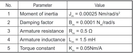
[8].The load torque is in opposite direction to mo-tor mo-torque as shown by the opposite arrows di-rection in Figure 1. Effective tuning of PID gains using LQR is based on the accuracy with which the system is modelled. The transfer function of DC motor is obtained by using the internal pa-rameters of DC motor from Table 1 [9].
Table 1. Parameters of DC motor
No. Parameter Value 1 Moment of inertia Jm = 0.00025 Nm/rad/s2
2 Damping factor Bm = 0.0001 Nm/rad/s 3 Armature resistance Rm = 0.5 Ω
4 Armature inductance Lm = 1.5 mH 5 Torque constant Km = 0.05Nm/A
IMPLEMENTATION OF PID
Automatic control system is playing an im-portant role in today’s modern society and due to ease of use and reliability PID is one of the most
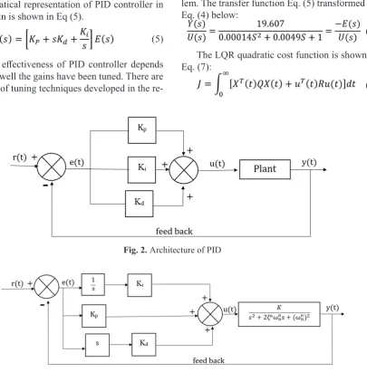
time-domain response of vast range of dynamic systems [10]. The Proportional term performs con-trol action proportional to the error, Integral term minimizes the steady state error by low frequency reparation through integrator and Derivative term improves the natural response of process by high frequency reparation through differentiator [11] PID calculates the error value which is the differ -ence between the desired and the actual value of the system and attempts to reduce the error by ad-justing the process control inputs [12].The archi-tecture of PID controller is shown in Figure 2.
Where, Kp, Ki and Kd are gains of Propor-tional, Integral and Derivative elements of PID controller. The three controllers are connected in parallel and their output signal drives the plant. The output of plant or process is measured and compared with the set-point via feedback to find the error and then PID uses this error to again cal-culate the control signal and this process contin-ues until the desired steady state is achieved. The mathematical representation of PID controller in S-domain is shown in Eq (5).
(5)
The effectiveness of PID controller depends on how well the gains have been tuned. There are number of tuning techniques developed in the
re-cent past to make PID more robust and more ef-fective in dynamic environments. In this research work Linear Quadratic Regulator (LQR) is used to get optimal gains for effectively controlling the speed of DC motor. The tuning technique and the implementation flow chart is discussed below.
PID tuning using LQR
Conventional optimal control theory has been revolutionized in recent years to develop the fa-mous LQR which reduces the excursion in state trajectories of a process while requiring least ef-fort of controller [13]. This classic behavior has encouraged control system engineers to use LQR for tuning of PID gains [14]. LQR based PID tun-ing is shown in Figure 3 [15].
In the belowe figure for LQR tuning reference input r(t) =0 as external reference input does not affect the controller tuning so as r(t) is zero then y(t) = –e(t) which is a valid linear regulator prob-lem. The transfer function Eq. (5) transformed by Eq. (4) below:
(6)
The LQR quadratic cost function is shown in Eq. (7):
(7)
Fig. 2. Architecture of PID
Where Q and R are weight matrices, u(t) is the control signal and X(t) is the state vector. To get optimal control above cost function is to be minimized which results in the Eq. (8) given below [15]:
(8) Where P is a symmetric positive definite solution of continuous algebraic Ricatti equation shown in Eq. (9):
(9) Eq. (6) is transformed in to the differential form shown in Eq. (11):
(10)
(11) Declare three state variables x1, x2 and x3 as shown below in Eq. (12)
(12)
So the Eq. (11) minimizes to Eq. (13):
(13) State space equation of Eq. (13) is shown in Eq. (14):
(14)
(15)
(16) As Q is a symmetric positive weighting matrix and R is the constant weighting factor, so generally R is kept fixed while Q is varied to get optimized control signal from LQR.
(17)
Characteristics of a closed loop polynomial system is shown in Eq. (18) [17]:
(18) Modify the above equation for preferred damping ratio (ζ) and natural frequency (ωn), the character-istic polynomial for a closed loop system is shown in Eq. (19):
(19)
By comparing the above two equations gains of PID can be found by the following relations: (20)
(21)
(22) By putting the values of open loop and closed loop ζ0,ω
n0,ζc,ωnc and m in above equations PID gains kp, ki and kd can be easily calculated. In this research work ζ0=0.00245 and ω
while desired closed loop values are ζc=1, ω nc=15 and m=9. Finally kp=207, ki=1549 and kd=7 have been calculated.
PID Implementation Flow Chart
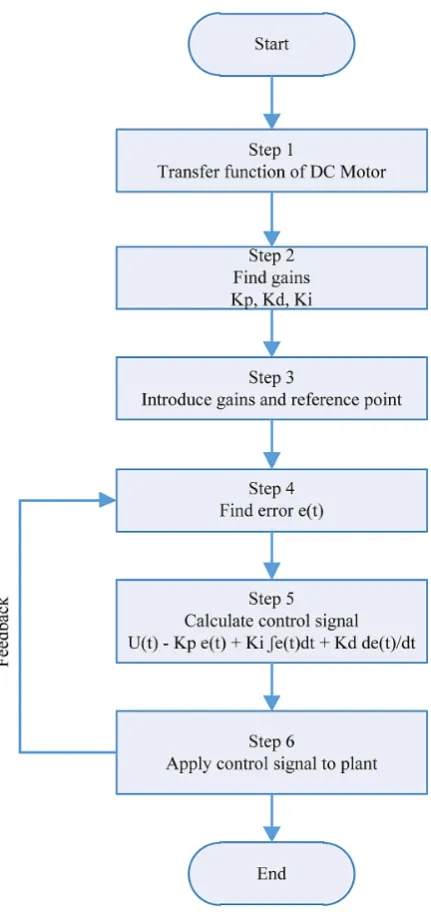
The first step to implement PID for speed control of a DC motor is to attain the transfer function of DC motor and then find the PID gains using LQR. After that introduce the reference point, introduce gains and find the difference be -tween the desired value and the actual value in the form of error to calculate the control signal that is applied to DC motor. Finally a feedback is taken from output to find the error and this proce -dure continues until the DC motor is regulated at desired speed. The implementation flow chart is shown in Figure 4.
SOFTWARE TOOLS
The software tools used in this research work to develop the simulations of implementation of PID on PIC24F series microcontroller for speed control of a DC motor are MPLAB and Proteus Professional. They are precisely discussed below.
MPLAB IDE
MPLAB Integrated Development Environ-ment (IDE) is software to develop programs for PIC microcontrollers. It is called IDE because it provides development, debugging and software services on a single platform. The Language tools present in MPLAB are Assembler (MPASM), Linker (MPLINK) and a C compiler (MPLAB C30). The newest version present at the time of this writing is MPLAB X IDE but in this research work MPLAB 8.10 version with C 30 compiler is used. The steps required to develop a program for the PIC controller and generate hex file using MPLAB is shown in Figure 5 [7].
Proteus
Proteus is classic Electronic Design Automa-tion (EDA) simulaAutoma-tion software. The huge device library and wide range of peripherals is the special feature of this simulator. The virtual instrumenta-tion feature offers a great platform for simulainstrumenta-tion of microcontroller units. Proteus Virtual System Modeling (VSM) uses mixed mode SPICE cir-cuit simulation, animated components and
mi-Fig. 4. Flow Chart of PID Implementation
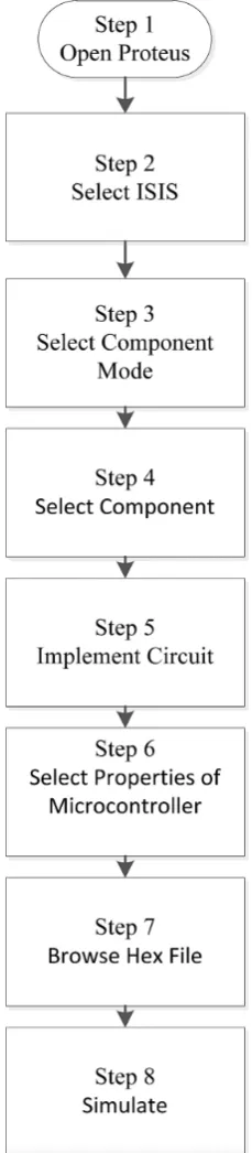
croprocessor models to make possible complete simulations of microcontroller based designs. For the first time ever, it is possible to develop and test such designs before a physical prototype is constructed [16].The steps required to simulate microcontroller based applications in Proteus are shown in Figure 6.
SIMULATIONS
algorithm flow chart and circuit diagram is elabo -rated below.
Block diagram
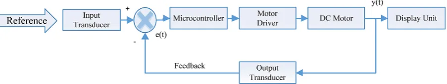
The block diagram of implementation of PID on microcontroller for speed control of a DC mo-tor in Proteus is shown in Figure 7. Input trans-ducer converts the reference speed to the form compatible to microcontroller then
microcon-troller generates the required PWM by using PID control technique to control the motor speed at desired value. Motor driver regulates the voltage at terminals of DC motor. Output transducer mea-sures the real speed and transforms it to the form compatible to the microcontroller and send the value to microcontroller as a feedback for estima-tion of PWM. Display unit presents the results of actual speed and the percentage of duty cycle. Fig. 5. Steps to develop program for PIC
Input transducer / User interface
Keypad is used as a user interface to provide the desired reference speed for the DC motor and it is also used to select three different cases for speed control of DC motor. In this paper a 4*4 keypad is used. Keypad uses its internal libraries to enable scanning of 4*4 switch array and return the data related with the pressed button. Interfac-ing of keypad with microcontroller can be done in three ways; depending on the design require-ments and pin resources. They are scanning meth-od, logic change interrupt method and external in-terrupt using IC. In this paper scanning method is used which needs 8 pins for interfacing [7].
Microcontroller
PIC24FJ128GA010 belongs to CMOS family with less power consumption because of power handling modes i-e sleep, idle and alternate clock modes. Its operating voltage range is 2.0 V -3.6V. It is a general purpose 100-pin microcontroller with a modified Reduced Instruction Set comput -er (RISC) architecture which can op-erate at up to 32 MHz crystal oscillator with speed of 16 Mega Instructions Per Second (MIPS) [17]. PIC micro-controller uses PID algorithm to generate PWM pulses for regulation of DC motor. PWM genera-tion is elaborated below.
Pulse Width Modulation
PWM is a versatile method of providing varying amounts of electrical power between fully ON and fully OFF. A normal power switch with some power source provides full power only, when switched on. PWM is a relatively new technique, and can be implemented by the latest electronic power switches. In PIC24FJ-128GA010 Output Compare Module (OCM) is utilized to generate PWM and it has three pins to produce PWM they are OC1, OC2 and OC3. OCM has number of working modes i-e
Single Compare Match Module, Double Com-pare Match Mode Generating and Simple PWM. OCM is initialized using OCXCON control reg-ister and for generating PWM the first three bits of OCXCON register (OCXCON<2:0>) are set to (110)2. PWM of specific frequency is gener -ated by writing the number of cycles required to produce PWM period to period register of cho-sen timer. The period register value is calculated by using the following Eq. (23) [17].
PWM Period – [(PRY) +1]·TCY·(Prescale Value) (23) where: PWM frequency = 1/[PWM Period] and
TCY = 2/FOSC.
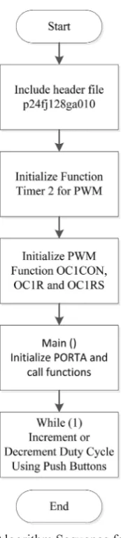
The duty cycle of PWM is set by putting its value in OCXRS register but first put the initial value of duty cycle to OCXR register then OCXR register becomes only Read-Only duty cycle reg-ister after that OCXCON control regreg-ister is ini-tialized for simple PWM generation [17]. In this research work PWM is generated with frequency of 800 Hz using 16MHz crystal oscillator. The calculated value of clocks for period register us-ing (23) is (2710)16 and the initial value of PWM written to OCXR register is (0F)16. Timer 2 is used for generating interrupt with a frequency of 800Hz. PWM generation is developed in MPLAB by following the sequence of commands shown in Figure 8 [7].
Motor driver
Controller generates 5V PWM and is applied at the input of the driver circuit. Because of PWM driver circuits gives pulses of 12V DC voltage to regulate power at the terminals of DC motor. In this paper Dual H-Bridge IC L293D is used as motor driver. This motor driver is a high current, high voltage four channels driver which is com-patible with both DTL and TTL logic. Each chan-nel is capable of producing 600mA output current and can provide up to 1.2A peak output current to drive motor.
DC motor
The DC motor used in Proteus has 12V and 3600RPM voltage and speed ratings respectively. The DC motor has built in load torque capability. The speed of DC motor is controlled by PID for 0% load torque, 25% load torque and 50% load torque.
Output transducer
Encoder is used to measure the real speed of motor and converts it into a form compatible to microcontroller. This information is given back to the controller for the estimation of control signal to generate accurate PWM to drive the motor at desired speed. The DC motor used in Proteus has built in encoder to measure speed.
Display unit
LCD is used to show real time results and found in number of applications. In this research work a
16*2 display LCD module is used. A 16*2 LCD has 16 characters in each line and there are two such lines. LCD operations are based on two registers namely command and data where command reg-ister controls the operation and data regreg-ister stores the data to be displayed [7]. In this paper LCD will display real speed, percentage of duty cycle and the number of loops in which speed is regulated.
Microcontroller based PID speed controller algorithm
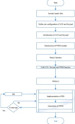
To develop a complete algorithm for micro-controller based PID speed micro-controller in MPLAB first include header files then declare the pin connections of both Keypad and LCD after that initialize keypad, LCD and PWM functions and also define an Interrupt Service Routine (ISR). In ISR feedback is taken from motor and converted to e(t) to be used by PID to calculate the control signal. In main loop all the functions are called and in while loop PID is implemented and PWM is generated and it is further given to the motor driver to regulate the speed and during while loop if interrupt occurs ISR is executed and this pro-cedure continues for ever until system is stopped. The algorithm flow chart is shown in Figure 9.
Circuit diagram
The circuit diagram of microcontroller based PID speed controller of DC motor is shown in Figure 10. In the above figure LCD and Keypad are connected to PORT B and PORT A respec-tively. The PWM is generated at Pin No. 72 and it is connected to the input of motor driver. The output terminals of motor driver are connected to DC motor. Motor encoder output in form of pulses is given at Pin No. 73 as a feedback to gen-erate required PWM using PID algorithm. In this way microcontroller based PID speed controller regulates the speed of DC motor.
RESULTS
The simulation results of speed control of DC motor are presented in three cases:
• Case 1: Speed control of DC motor without load torque.
• Case 2: Speed control of DC motor with 25% load torque.
• Case 3: Speed control of DC motor with 50% load torque.
The PID gains in all three cases are same. They are kp=207, ki=1549 and kd=7.
Case 1
The simulation results of speed control with set-point of 100RPM and with 0% load torque are presented in Figure 11. In the Figure 11 LCD shows the actual speed, percentage of duty cycle and number of loops required reaching that speed and oscilloscope shows the respec-tive PWM for that speed. From above figure it is clear that the DC motor speed reaches peak overshoot of 104RPM in 8 loops with duty cycle of 33% and then successfully settles after two loops at 99RPM only giving 1% of steady state error with 31% duty cycle.
Case 2
The simulation results of speed control with set-point of 100RPM and with 25% load torque presented in Figure 12. From Figure 12 it is clear that by adding the load torque to DC motor more duty cycle of PWM and more time required to reach the same speed so in case 2 DC motor speed reaches peak overshoot of 104RPM in 11 loops with duty cycle of 39% and then successfully set-tles after one loop at 99RPM only giving 1% of steady state error with 38% duty cycle.
Case 3
presented in Figure 13. From Figure 13 it is clear that increasing the load torque to DC motor re-sults in large increase in duty cycle of PWM and more time required to reach the same desired speed so in case 3 DC motor speed reaches peak
overshoot of 102 RPM in 13 loops with duty cy-cle of 61% and then successfully settles after two loops at 97RPM giving 3% of steady state error with 59% duty cycle. The simulation results of all three cases have been summarized in Table 2.
From Table 2 it is evident that even by in-creasing the load torque PID effectively regu-lates the speed of DC motor at desired speed but both peak time (tp) and settling time (ts) also increases. The steady-state error remains constant in first two cases but varies in last case. The duty cycle of PWM has also been in-creased to regulate the motor at desired speed with increase in load torque. It is also clear that in dynamic environments PID gains have to be adjusted again and again to get optimum tran-sient and steady state response.
Fig. 10. Circuit diagram in Proteus
a)
b)
Fig. 11. Speed Control of DC motor without Load Torque: a) Overshoot Results, b) Steady State Results
a)
b)
Fig. 12. Apeed Control of DC motor with 25% Load Torque: a) Overshoot Results, b) Steady State Results
a)
b)
CONCLUSION
In this research work PID has been implement-ed on a 16-bit PIC24FJ128GA010 microcontroller for speed control of a DC motor. The Proteus sim-ulations have been analyzed without load torque, with 25% load torque and with 50% load torque. In all three cases PID effectively controls the speed of DC motor but with increased in tp, ts and duty cycle of PWM which motivates the researchers to work on online optimization of PID gains. More-over, implementation of PID on PIC24F series mi-crocontroller using MPLAB and Proteus software has given an opportunity to implement and test more control techniques i-e Fuzzy Logic, Linear Quadratic Regulator (LQR) and Model Predictive Control (MPC) for not only Single Input Single Output (SISO) but also for Multiple Input Multiple Output (MIMO) systems as well. Finally this paper also convinces the idea of using the combination of these two tools in educational sector to enhance embedded system skills.
REFERENCES
1. Shrivastava S., Rawat J., Agarwal A.: Controlling DC Motor using Microcontroller (PIC16F72) with PWM. International Journal of Engineering Re-search, 1, 2012, 45-47.
2. Bhagat N.A., Bhaganara M.: DC Motor Speed Con-trol using PID ConCon-trollers, Electronic System Design Course Project. University of IIT Bombay, 2009. 3. Kamar U., Narvey R.: Speed Control of DC Motor
Using Fuzzy PID Controller. Advance in Electron-ic and ElectrElectron-ic Engineering, 3, 2013, 1209-1220. 4. Saridhar N., Ramrao N., Singh M.K.: PID
Control-ler Auto Tuning using ASBO Technique. Journal of Control Engineering and Technology, 4, 2014, 192-204.
5. Das S., Pan I., Halder K., Das S., Gupta A.: LQR based improved discrete PID controller design via optimum selection of weighting matrices using frac-tional order integral performance index. Applied Mathematical Modeling, 37, 2013, 4253-4268
6. Mukherjee A., Ray S., Das. A.: Development of Microcontroller Based Speed Control Scheme of BLDC Motor Using Proteus VSM Software. , In-ternational Journal of Electronics and Electrical Engineering, 2014, 2, 1-7.
7. Aslam S., Hannan S., Haider A., Tariq M.H.: Ex-ploring PIC 24F Series Microcontroller using MPLAB and Proteus. Journal of Current Research in Science, Accepted and Published in June, 2016. 8. Hamed B., Al-Mobaid M.: Fuzzy PID controllers
using FPGA technique for real time DC motor speed control. International journal of Intelligent control and automation, 2, 2011, 233-240.
9. Aslam S., Hannan S., Haider A.: Effect of Laguerre
function parameters on MPC performance for speed control of a DC motor. Journal of Control Engineering and Technology, 6, 2016, 1-13. 10. Singh A.P., Narayan U., Verma A.: Speed Control
of DC Motor using Pid Controller Based on Mat-lab. Innovative Systems Design and Engineering, 4, 2013, 1-7.
11. Hang C.C, Sin K.K.: A comparative performance study of PID auto- tuners. IEEE Control System, 11, 1991, 41-47.
12. Vikhe P., Punjabi N., Kadu C.: Real Time DC Motor Speed Control using PID Controller in LabVIEW, International Journal of Advanced Re-search in Electrical, Electronics and Instrumenta-tion Engineering, 3, 2014, 12162-12167.
13. Anderson B.D.O., Moore J.B.: Optimal Control: linear quadratic methods, Prentice-Hall
Interna-tional, Inc., Englewood Cliffs, NJ, 1989
14. He J.B., Wang Q., Lee T.H.: PI/PID controller tun-ing via LQR approach. Chemical Engineertun-ing Sci-ence, 5, 2000, 2429-2439.
15. Kumar V.E., Jerome J.: LQR based optimal tuning of PID controller for trajectory tracking of mag-netic levitation system, International conference on design and manufacturing (Procedia Engineering), 64, 2013, 254-264.
16. Chen J.: Application of Proteus Software in MCU teaching. Second International Conference on Me-chanic Automation and Control Engineering, 2011, 6359-6362.
17. Microchip, PIC24FJ128GA010, datasheet, 2006.
Table 2. Simulation results of all cases
No. Case Load torque Set-point (RPM) (tp) (loops)Peak time Setting time (Ts) (loop) Over shoot Steady state error PWM (duty)
1 1 0% 100 8 10 4 1 31
2 2 25% 100 11 12 4 1 38