Research Journal
Volume 10, No. 29, March 2016, pages 85–96
DOI: 10.12913/22998624/61936 Research Article
Received: 2015.12.15 Accepted: 2016.02.01 Published: 2016.03.01
WIDE-AREA BASED ON COORDINATED TUNING OF FUZZY PSS
AND FACTS CONTROLLER IN MULTI-MACHINE ENVIRONMENT
Homayoun Ebrahimian1, Ebrahim Farzaneh Sheikhahmad2,*
1 Department of Basic Sciences, School of Medicine, Ardabil University of Medical Sciences, Ardabil, Iran 2 Department of Electrical Engineering, Ardabil Branch, Islamic Azad University, Ardabil, Iran
* Corresponding author e-mail: [email protected]
ABSTRACT1
In this paper coordination of fuzzy power system stabilizer (FPSS) and flexible ac
transmission systems (FACTS) have been considered in a multi-machine power sys-tem. The proposed model, has been applied for a wide-area power syssys-tem. The pro-posed FPSS presented with local, nonlinear feedbacks, and the corresponding control
synthesis conditions are given in terms of solutions to a set of linear matrix inequali
-ties (LMIs). For this model, in fuzzy control synthesis, the new proposed control de-sign method is based on fewer fuzzy rules and less computational burden. Also, the parameters of FACTS controller have been evaluated by improved honey bee mating optimization (IHBMO). The effectiveness of the proposed method has been applied
over two case studies of single-machine infinite-bus (SMIB) and two areas four ma
-chine (TAFM) Kundur’s power system. The obtained results demonstrate the superi-ority of proposed strategy.
Keywords: wide area power system, FPSS, FACTS, improved honey bee mating op-timization.
INTRODUCTION
By increasing the complexity of power grid
interconnections, power systems may become
increasingly vulnerable to low frequency oscil -lations, especially inter-area oscillations. Actu-ally, damping effectiveness of local measurement based controls is limited because local measure-ments have limited modal observability [1–3]. In such situations, the use of wide-area signals in which the desired oscillatory modes may be
readily observable could be more beneficial in
damping area oscillations of a large inter-connected system. The ability and a potential to use wide-area signals for control purposes has
increased since a significant investment has been
made in the U.S. in deploying synchrophasor measurement technology.
These oscillations have also resulted in insta-bility and blackouts in the power system. A tra-ditional approach to damp out these oscillations
is through conventional power system stabilizer
(CPSS), forming part of the generator excitation
system. Besides PSS, FACTS devices are also ap-plied to enhance system stability. Particularly, in multi-machine systems, using only conventional
PSS may not provide sufficient damping for in -ter-area oscillations. In these cases, FACTS con-trollers are effective solutions. These concon-trollers usually employ local signals as inputs and may not always be effective to damp out the interarea modes of oscillations. But CPSSs cannot satisfy the power system stability enhancement. For this purpose intelligent methods have been applied for tuning the parameters of PSSs [4–7].
Recently, FPSS has been proposed for sta-bility problem in multi-machine power systems. In this paper, Takagi-Sugeno (T-S) based fuzzy controller has been proposed as an FPSS con-troller. Actually, there are two types of methods
to overcome the difficulty of classic T-S control
-tween the conservatism and the computational burden by reducing unimportant decision vari-ables [8]. However, the obtained controllers are still with a number of control rules, which may be unfavorable for implementation. Anoth-er method is that the original nonlinear model
is first simplified as much as possible. Then, a
fuzzy model with fewer fuzzy rules is
construct-ed basconstruct-ed on the simplificonstruct-ed nonlinear model by using a fuzzy local approximation technique [9].
However, the designed control laws based on the fuzzy model may not guarantee the stability of the original nonlinear system. In this paper, a class of T-S fuzzy models with local nonlinear
models is exploited to describe the considered
nonlinear systems. A new fuzzy control scheme with local nonlinear feedbacks is proposed, and the corresponding control synthesis conditions are developed in terms of solutions to a set of
LMIs. In contrast to the existing methods for
fuzzy control synthesis, the new proposed con-trol design method is based on fewer fuzzy rules and less computational burden. Moreover, the local nonlinear feedback laws in the new fuzzy controllers are also helpful for achieving good control effects [10–12].
By considering the coordination of FPSS and FACTS we will evaluate the effects of these de-vices in power system stability by considering the wide-area coordinating (WAC). Accordingly, to enhance stability margins and control oscillatory modes by adding supplementary damping devices we will use the global remote signals which have been suggested since the introduction of the pha-sor measurement unit (PMU) technology. Remote signals transmit knowledge related to the overall network dynamics, in contrast with local signals, which often lack good observability of some
sig-nificant inter-area modes [13]. Even though WAC
controllers involve additional communication
equipment, their implementation may turn out to
be more cost effective than installing new
con-trol devices if the additional operating flexibility
achieved in critical power systems compensates
for the equipment cost [14–15].
PROBLEM STATEMENT
Power system modelingIn this paper a single machine and multi-machine power systems are considered as a test cases where the third order model is presented in
[16–17]. Actually, the proposed power system con-sists of four generators and the electrical and me-chanical part of ith generator is modeled as follow:
.
0
( ) ( )
i t w t wi
δ = −
.
0
0
( ) ( ( )) i ( ( ) )
i mi ei i
i i
w D
w t P P t w t w
M M = − − − . ' 1 ( ) ( ( ) ( ))
qi fi qi
doi
E t E t E t
T
= −
' '
( ) ( ) ( ). ( )
qi qi di di di
E t =E t + x −x I t
2 2 2 2 1/2
1
( ) [ 2 cot ]
ti si qi si qi si di dsi ei i dsi
V t x E V x x x x P
x δ
= + +
' ' 1
( ) n ( ) ( )( sin( ( )) cos( ( )))
ei qi qj ij ij ij ij
j
P t E t E t B δ t G δ t
=
=
∑
+' ' 1
( ) n ( ) ( )( sin( ( )) cos( ( )))
ei qi qj ij ij ij ij
j
Q t E t E t G δ t B δ t
= =
∑
+ ' ' 1 ( )( ) ( )( sin( ( )) cos( ( )))
( )
n
ei
di qj ij ij ij ij
j qi
Q t
I t E t G t B t
E t δ δ = =
∑
− = ' ' 1 ( )( ) ( )( sin( ( )) cos( ( )))
( )
n
ei
qi qj ij ij ij ij
j qi
P t
I t E t B t G t
E t
δ δ
=
=
∑
− =( ) ( )
qi adi fi
E t =x I t
Also, it can be presented after mathematical
transformers where, ΔPe, Δw and ΔVtare quanti -ties; ' ' . ' ' 0 . 0 ' . ' 0 ' ' 0 0
Ei Vi Vi Ei
Ei Ei
di Vi di Vi
ei ei
d i
i i
i i fdi
i i
Ei
ti Ei Vi Ei Vi Ei ti
d i Vi di Vi Vi Vi di Vi
S S S R S R
T S T S
P P T
w D
w w E
H H
R
V S S S S S V
T R
T R S R T S
− − ∆ ∆ ∆ = − − ∆ + ∆ ∆ ∆ − − −
where: ΔPei – is the state deviation in generator electromagnetic power for the ith
sub-system,
Δωi – is the state deviation in rotor angu-lar velocity for the ith subsystem,
ΔVti – is the state deviation in the ter-minal voltage of the generator for the ith
subsystem.
2
' '
' 2
' '
cos cos 2
cos cos 2
qi si d i q i
Ei i si i
d i d i q i qi si d i q i
Ei i si i
d i d i q i
E U X X
S U
X X X
E U X X
S U
X X X
δ δ δ δ ∑ ∑ ∑ ∑ ∑ ∑ ∑ ∑ ∑ ∑ − = + − = + ' ' sin sin , / si Ei i d i si Ei i d i ti ti Vi Ei Vi Vi Ei
i qi U R X U R X U V
S S R R S
The linearized rotor motion equation for syn -chronous generator can be described as:
J d w m e D
T T T T
dt
∆
= ∆ − ∆ − ∆
where: ΔTm– is the mechanical input torque, ΔTe – is the electromagnetic torque, and ΔTe = K1Δδ + K2Δδ. By neglecting the
K2ΔE’
q the formulation can be described
as;ΔTe=K1Δδ+ΔTD.
D – is the natural damping constant.
Accordingly the above equation after Laplace transformer and Δw = sΔδ/w0 can be described as:
2
1
0 0
J s s
T K D
w w
δ δ δ
∆ = − ∆ − ∆
Which can be described as:
2
0 1 0
J
T s +Ds w K+ =
Or
2 2 2 0
n n n
s + ζ w s w+ =
Accordingly, we can achieve the following
equation from above equations:
0 1 0 1 / 2 / n J n J
D w T K
w w K T
ζ =
=
where: ξn – is the damping factor,
wn– is the un-damped mechanical
oscilla-tion frequency.
STRUCTURE OF PROPOSED
CONTROLLER
Fuzzy power system stabilizer
Regarding some complexity in wide area pow -er system and variation of the loads and network conditions, it can be considered as a multi-input and multi-output system. The T-S fuzzy controller is the best choice of this application. So, we can obtain the following T-S fuzzy model as:
1 1 2 2
.
1 2
1 1 2
( ) ( ) , ..., ( )
( ) ( ) ( ) ( ) ( )
( ) ( ) ( ) ( ) ( )
i i p ip
i i i i
i i i zi
IF v t is and v t is v t is
THEN x t A x t B t B u t G t
z t C x t D t D u t G t
ω φ
ω φ
Γ Γ Γ
= + + +
= + + +
where: i = 1,... , r. r is the number of IF–THEN
rules, v(t) = [v1(t) v2(t) · · · vp(t)]T ∈ Rp×1 are the premise variables, and Γij are the fuzzy sets [18].
By using the fuzzy inference method with a
singleton fuzzifier and product inference and cen
-ter average defuzzifiers, the final T-S fuzzy model
is obtained as follows:
1 2 . 1 1 ( ( ))( ( ) ( ) ( ) ( )) ( ) ( ( )) r
i i i i i
i
r
i i
W v t A x t B t B u t G t
x t
W v t
ω φ = = + + + =
∑
∑
1 1 2
1 1 ( ( ))( ( ) ( ) ( ) ( )) ( ) ( ( )) r
i i i i zi
i
r i i
W v t C x t D t D u t G t
z t
W v t
ω φ = = + + + =
∑
∑
Where W v ti( ( ))= Πpj=1ηij( ( )). ( ( ))v tj ηij v tj is the
grade of membership of vj(t) in Γij, where it is as-sumed that
∑
ri=1W v ti( ( )) 0, ( ( )) 0,> W v ti ≥ i=1,2,...,r.Denote αi(v(t)) = (wi(v(t))) / (
∑
ri=1W v ti( ( ))); then 0≤αi( ( )) 1v t ≤ and 1 ( ( )) 1r i i=α v t =
∑
Where αi(v(t)) is said to be normalized mem-bership functions. Let α(v(t)) = [α1(v(t)), α2(v(t)),
..., αr(v(t))]T, and denote α(v(t)) as α for a brief
description. So, we can write:
.
1 2
( ) ( ) ( ) ( ) ( ) ( ) ( ) ( ) ( )
x t =Aα x t +B α ωt +B α u t G+ α φ t
1 1 2
( ) ( ) ( ) ( ) ( ) ( ) ( ) z( ) ( )
z t =C α x t +D α ωt +D α u t G+ α φ t
with
1 1
1 1
2 2
1 1
1 1 1 1
1 1 2 2 1 1 ( ) ( ) ( ) ( ) ( ) ( ) ( ) ( ) ( ) ( ) ( ) ( ) ( ) ( ) ( ) ( ) r r
i i i i
i i
r r
i i i i
i i
r r
i i i i
i i
r r
i i z i zi
i i
A t A B t B
B t B G t G
C t C D t D
D t D G t G
α α α α α α α α α α α α α α α α = = = = = = = = = = = = = = = =
∑
∑
∑
∑
∑
∑
∑
∑
In fact, A(α)x(t), B1(α), B2(α), G(α), C1(α)
x(t), D1(α), D2(α), and Gz(α) in fuzzy model are the new descriptions of f a(x(t)), h(x(t)), g(x(t)),
fb(x(t)), fza(x(t)), hz(x(t)), gz(x(t)), and fzb(x(t)) by fuzzy membership functions, respectively. The
following lemma will be useful in the sequel.
Lemma 2: If the following conditions are
hold:
0, 1
1 1 ( ) 0, 1
1 2
ii
ii ij ji
M i r
M M M i j r
r
< ≤ ≤
+ + < ≤ ≠ ≤ −
Then we can write;
1 1
1
0, 1
0
, , 1 , 0 1, 1
ii
r r
i j ii i j
r
i i i
M i r
M
where i r satisfy
α α
α α α
= =
=
< ≤ ≤
<
≤ ≤ ≤ ≤ =
∑∑
Fuzzy PSS control strategy
In this paper, the H∞ control strategy and guaranteed cost control have been considered. Also, for local nonlinear feedbacks control and the corresponding control synthesis conditions
has been solved by linear matrix inequalities
(LMIs). We leave this section for preventing
more description where, [19] presents further dis
-cussion in this field.
Flexible AC transmission systems controller
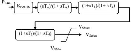
The structure of the proposed FACTS con-troller has been presented in Figure 1. Also, lo-cal signals of FACTS devices are applied for the damping control. In this paper, the active power
flow through the series FACTS device line P is employed [20–21].
Fig. 1. The flowchart of FACTS controller
The parameters of the proposed FACTS con-troller have been optimized by IHBMO in this pa-per. For this purpose we introduce this algorithm
in the next section
IMPROVED HONEY BEE MATING
OPTIMIZATION
Standard HBMO
This section reviews briefly the original
HBMO. In order to deepen the concept see ref
[22]. At the start of the flight, the queen is ini -tialized with some energy content and returns to her nest when her energy is within some thresh-old from zero or when her spermatheca is full. In developing the algorithm, the functionality of workers is restricted to brood care, and therefore, each worker may be represented as a heuristic which acts to improve and/or take care of a set of
broods. A drone mates with a queen probabilisti -cally using an annealing function as:
( ) ( )
( , )
f S t
prob Q D e
−∆ =
Where Prob (Q, D) is the probability of add-ing the sperm of drone D to the spermatheca of
queen Q (that is, the probability of a successful mating); ∆(f) is the absolute difference between
the fitness of D (i.e., f(D)) and the fitness of Q
(i.e., f(Q)); and S(t) is the speed of the queen at
time t. It is apparent that this function acts as an annealing function, where the probability of
mat-ing is high when both the queen is still in the start of her mating-flight and therefore her speed is high, or when the fitness of the drone is as good as the queen’s. After each transition in space, the queen’s speed, S(t), and energy, E(t), decay using
the following equations:
(
)
( )
S t 1 + = αHBMO S t× E(t+1) = E(t) – γHBMO
where: αHBMO(t) – is speed reduction factor and γHBMO – is the amount of energy reduction after each transition (α, γ ϵ [0,1]).
Thus, HBMO algorithm may be constructed
with the following five main stages:
• Step 1: The algorithm starts with the mating
flight, where a queen (best solution) selects
drones probabilistically to form the sperma-theca (list of drones). A drone is then select-ed from the list at random for the creation of broods.
• Step 2: Creation of new broods by
crossover-ring the drones’ genotypes with the queen’s
(Breeding process). The breeding process can
transfer the genes of drones and the queen to
the jth individual [23].
( )
i HBMO k i
child parent= +β parent −parent
Where βHBMO is the decreasing factor (βHBMO
~U (0, 1)).
• Step 3: Use of workers (heuristics) to conduct local search on broods (trial solutions).
• Step 4: Adaptation of workers’ fitness based
on the amount of improvement achieved on broods as follows:
( )
[0,1],0 1
k k k
i i HBMO HBMO i
HBMO HBMO
Brood Brood δ ε Brood
δ ε
= ± +
∈ < <
• Step 5: Replacement of weaker queens by fit -ter broods.
Interactive honey bee mating optimization (IHBMO)
without deterioration of at least one of the other objective values. Pareto dominance concept
clas-sifies solutions as dominated or non-dominated
solutions and the “best solutions” are selected from the dominated solutions. To sort
dominated solutions, the first front of the
non-dominated solution is assigned the highest rank and the last one is assigned the lowest rank. When comparing solutions that belong to the same front, another parameter called crowding distance is cal-culated for each solution. The crowding distance is a measure of how close an individual is to its neighbors. Large average crowding distance will result in better diversity in the population [24].
Fuzzy mechanism
Upon having the Pareto-optimal set of non-dominated solutions, the proposed approach pres-ents one solution to the decision maker as the best compromise solutions. Due to imprecise nature of the decision maker’s judgment, the ith objective
function is represented by a membership function
µi defined as [25]:
max
max min
( ) ( ) i i gi i gi
i i
f f p
p
f f
µ = −
− where: fimax and f
imin are the maximum and mini
-mum values of ith objective, respectively.
0 ( ) 0
( ) ( ) 0 ( ) 1
1 ( ) 1
i gi
i gi i gi i gi
i gi
p
FDM p p p
p
µ
µ µ
µ ≤
= < <
≥
For each non-dominated solution k, the nor-malized membership function FDMk
2
1 2
1 1
( )
k i gi
k i
M
j i j i
FDM p
FDM
FDM
=
= =
=
∑
∑∑
The best compromise solution of stability
problem is the one having the maximum value of
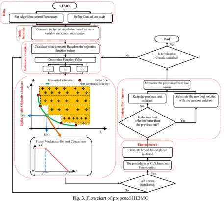
FDMk as a fuzzy decision making function. Where M is the total number of non-dominated solutions. Then all the solutions are arranged in descending order according to their membership function val-ues which will guide the decision makers with a priority list of non-dominated solutions in view of the current operating conditions. Figure 2 shows the membership structure μc for the fuzzy logical variable signifying the total fuel cost fi(Pgi). Also,
the flowchart of the proposed method has been
presented in Figure 3.
NUMERICAL RESULTS AND DISCUSSION
One machine infinite busFor stability assessment of power system
ad-equate mathematical models describing the sys -tem are needed. The sys-tem behaviour following such a disturbance is critically dependent upon the magnitude, nature and the location of fault
and to a certain extent on the system operating
conditions. A schematic diagram for the proposed
first test case is presented in Figure 4.
The disturbances are given at t = 1 sec. Sys-tem responses in a form of slip (Sm) are plotted. The following types of disturbances have been considered [26]:
• Scenario 1: A step change of 0.1 pu in the
in-put mechanical torque.
• Scenario 2: A three phase-to-ground fault for
100 ms at the generator terminal.
The convergence trend of proposed algorithm is presented in Figure 5. Also, the achieved results for FACTS controller are presented in Table 1.
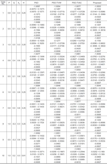
In the following, Figure 6 presents the system response at the lagging power factor operating conditions with weak transmission system for sce-nario 1. It is clear that the proposed method could provide better stability conditions. In this test case, the proposed model has been compared with other three algorithms which have been resented in [26]. The mentioned algorithms are particle swarm op-timization (PSO) and two other versions of this algorithm, named PSO-TVAC and PSO-TVIW [27]. Also, Figure 7 presents the system response in scenario 2 with inertia H’= H/4.
Furthermore, to demonstrate the robustness performance of the proposed method, in the some
operating condition for scenario 1, the Eigen val -ues of the system with comparison of these meth-ods has been presented in Table 2. All of the
ly from [26]. It is clear to see that the eigenvalues of the system with the proposed model are farther
than the imaginary axis and the system stability
margin is more than other methods.
For more information about the proposed al-gorithm the computational results which are used in this paper through several runs of the proposed
technique. The computational results are shown
in Table 3. Fig. 3. Flowchart of proposed IHBMO
Fig. 4. Schematic diagram of one machine infinite
bus system
Fig. 5. Fitness convergence of proposed method
Table 1. Parameters for proposed algorithms
K T1 T2 T3 T4
Table 2. The Eigen values of system with different PID for scenario 1 Proposed PSO-TVAC PSO-TVIW PSO H Xe Q P Case No. -1.0053 -0.1232 -0.0144 + 0.0586i -0. 0144 - 0. 0586i -0.0324 -0.0007 -1.0077
-0.1065 -0.0277 + 0.0728i
-0.0277 - 0.0728i -0.0355 -0.0010 -1.0054
-0.1287 -0.0192 + 0.0715i
-0.0192 - 0.0715i -0.0326 -0.0008 -1.0097
-0.0070 + 0.1577i -0.0070 - 0.1577i -0.1573 -0.0242 -0.0005 3.25 0.3 0.4 0.8 1 -1.0036 -0.1257 -0.0200 + 0.0616i -0. 0200 - 0. 0616i -0.0240 -0.0007 -1.0069
-0.1099 -0.0312 + 0.0672i
-0.0312 - 0.0672i -0.0260 -0.0010 -1.0049
-0.1298 -0.0228 + 0.0659i
-0.0228 - 0.0659i -0.0249 -0.0008 -1.0088
-0.0096 + 0.1480i -0.0096 - 0.1480i -0.1584 -0.0188 -0.0005 3.25 0.3 0.1 0.5 2 -1.0031 -0.1183 -0.0096 + 0.0602i -0. 0096 - 0. 0602i -0.0427 -0.0007 -1.0084
-0.0260 + 0.0752i -0.0260 - 0.0752i -0.1026 -0.0420 -0.0010 -1.0059
-0.1277 -0.0171 + 0.0739i
-0.0171 - 0.0739i -0.0373 -0.0008 -1.0106
-0.0054 + 0.1620i -0.0054 - 0.1620i -0.1565 -0.0273 -0.0005 3.25 0.3 0.5 1.0 3 -1.0040 -0.0765 + 0.0276i -0.0765 - 0. 0276i -0.0101 + 0.0487i -0.0101 - 0.0487i
-0.0008 -1.0061
-0.0827 + 0.0465i -0.0827 - 0.0465i -0.0163 + 0.0492i -0.0163 - 0.0492i
-0.0011 -1.0042
-0.0125 + 0.0524i -0.0125 - 0.0524i -0.0874 + 0.0267i -0.0874 - 0.0267i
-0.0008 -1.0077
-0.0090 + 0.1309i -0.0090 - 0.1309i -0.1362 -0.0422 -0.0005 3.25 0.6 0.4 0.8 4 -1.0020 -0.0793 + 0.0256i
-0.0793 - 0.0256i -0.0143 + 0.0472i -0.0143 - 0.0472i
-0.0007 -1.0054
-0.0791 + 0.0439i -0.0791 - 0.0439i -0.0202 + 0.0447i -0.0202 - 0.0447i
-0.0011 -1.0038
-0.0168 + 0.0487i -0.0168 - 0.0487i -0.0833 + 0.0219i -0.0833 - 0.0219i
-0.0008 -1.0069
-0.0120 + 0.1297i -0.0120 - 0.1297i -0.1388 -0.0343 -0.0005 3.25 0.6 0.1 0.5 5 -1.0044 -0.0876 + 0.0318i
-0.0876 - 0.0318i -0.0052 + 0.0512i -0.0052 - 0.0512i
-0.0008 -1.0066
-0.0856 + 0.0485i -0.0856 - 0.0485i -0.0131 + 0.0507i -0.0131 - 0.0507i
-0.0011 -1.0046
-0.0904 + 0.0292i -0.0904 - 0.0292i -0.0093 + 0.0535i -0.0093 - 0.0535i
-0.0008 -1.0084
-0.0067 + 0.1293i -0.0067 - 0.1293i -0.1339 -0.0484 -0.0005 3.25 0.6 0.5 1.0 6 -1.0051 -0.0103 + 0.0599i
-0.0103 - 0.0599i -0.0975 -0.0807 -0.0006 -1.0077
-0.0791 + 0.0342i -0.0791 - 0.0342i -0.0191 + 0.0596i -0.0191 - 0.0596i
-0.0011 -1.0054
-0.0121 + 0.0621i -0.0121 - 0.0621i -0.1052 -0.0690 -0.0008 -1.0098
-0.0051 + 0.1443i -0.0051 - 0.1443i -0.1445 -0.0395 -0.0005 3.25 0.6 0.0 0.8 7 -1.0063 -0.1254 -0.0038 + 0.0699i -0.0038 + 0.0699i -0.0601 -0.0007 -1.0117
-0.0152 + 0.0838i -0.0152 - 0.0838i -0.0815 + 0.0127i -0.0815 - 0.0127i
-0.0011 -1.0082
-0.1295 -0.0057 + 0.0825i
-0.0057 - 0.0825i -0.0560 -0.0008 -1.0147
0.0029 + 0.1753i 0.0029 - 0.1753i -0.1534 -0.0427 -0.0005 3.25 0.3 -0.2 1.0 8 -1.0043 -0.1054 -0.0176 + 0.0533i -0.0176 + 0.0533i -0.0536 -0.0007 -1.0072
-0.0311 + 0.0561i -0.0311 - 0.0561i -0.0673 + 0.0191i -0.0673 - 0.0191i
-0.0010 -1.0051
-0.1108 -0.0209 + 0.0592i
-0.0209 - 0.0592i -0.0463 -0.0008 -1.0092
-0.0094 + 0.1432i -0.0094 - 0.1432i -0.1489 -0.0271 -0.0005 3.25 0.6 -0.2 0.5 9 -1.0223 -0.0252 + 0.180i -0.0252 + 0.180i -0.0806 -0.0427 -0.0007 -1.0363
-0.0328 + 0.2094i -0.0328 - 0.2094i -0.0516 + 0.0069i -0.0516 - 0.0069i
-0.0010 -1.0260
-0.0256 + 0.1867i -0.0256 - 0.1867i -0.0890 -0.0390 -0.0008 -1.0440
Two-area four-machine system
Kundur’s two-area four-machine (TAFM) system consisting of two fully symmetrical areas linked together by two 220 km, 230 kV
transmis-sion lines [27] is considered as a first case study
in this manuscript as shown in Figure 8. This power system typically is used to study the low
frequency electromechanical oscillations of a
large interconnected system. In this system, each
area consists of two generators, connected with
tie-lines between buses 7-8 and 8-9. Where, each
generator is assumed to be connected with gov-ernors, Automatic voltage regulator (AVR) and
IEEE ST1A type static exciter. The classic PSS
is connected to G2 and G3 based on and intelli-gent method presented in [28] to damp out local modes of oscillations. Then, the additional global signal is assumed to be provided to the stabilizer of the selected generator from a centralized wide Fig. 6. ΔTm=0.1 (p.u.) under Xe=0.3; PSO (dotted), PSO-TVIW (dashed-doted), PSO-TVAC (dashed)
and proposed (solid) a) P=0.8, Q=0.4 b) P=0.5, Q=0.1 c) P=1.0, Q=0.5
Fig. 7. ΔTm=0.1 (p.u.) under Xe=0.6 and H’=H/4; PSO (dotted), PSO-TVIW (dashed-doted), PSO-TVAC (dashed) and proposed (solid) a) P=1.0, Q=0.5 b) P=0.6, Q=0.0
Table 3. The average results over many runs of proposed algorithm
area controller to damp out the inter-area modes of oscillations.
In this test the critical mode is categorized in to two mode as; Mode one: −0.0046± 3.4279i
eigen-value, 0.25% damping by 0.5456 (Hz)
fre-quency, Mode one: −0.5297± 6.8076i eigen-val
-ue, 7.76% damping by 1.0835 (Hz) frequency [8].
Where, there is only one inter-area mode of oscil-lation, of 0.5456 (Hz) in the system. This factor and categories is presented in Table 1 and Table 2 for second and third case studies, respectively.
Also, damping contribution of FPSS and FACTS devices using the available line current as the control input for inter-area oscillation modes
has been presented in Figure 9. In this figure, (a)
Fig. 8. TAFM power system
Fig. 9. Damping contribution of FPSS and FACTS devices using the available line current as the control input for inter-area oscillation modes. (a) Scenario 1. (b) Scenario 2.
a)
b)
presents the changing the scenario 1 and (b) pres-ents the changing in scenario 2. These scenarios have been presented in the following for TAFM power system.
Also, in meta-heuristics algorithms the ma-ture convergence can be occurred. To tackle the above-mentioned problem, this algorithm has been run 10 times over the proposed problem.
Consequently, the best value of the consequence
con-dition and faults where two scenarios have been
considered to find the capability of the proposed
wide area control strategy. The achieved results demonstrate the validity of the proposed method in comparison of other methods. For this purpose,
at first we describe different scenarios in literature
in the following way:
Scenario one.For the first scenario, the per -formance of the proposed controller under
tran-sient conditions is verified by applying a 3-cycle
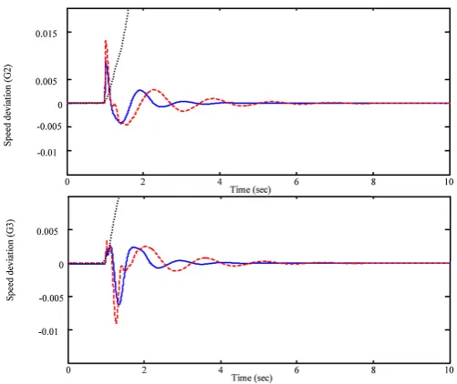
three-phase fault at t=1 sec. This scenario is ap-plied to bus 8 for Kundur’s power system. The fault is cleared by permanent tripping the faulted line.Theproposed strategy for wide-area control, has been compared with other model of wide-area control [8] and without wide wide-area controller. Figure 11 shows the speed deviations of G2 and G3 under nominal load condition. The obtained results demonstrate the validity of the proposed strategy where the overshoot (OS), undershoot (US) and settling time (ST) of the proposed strat-egy has a better behavior in comparison of other models. The mentioned control criteria evaluated
Fig. 10. Convergence trend of proposed algorithm
by the effectiveness of the proposed control strat-egy over generators deviations. Where, the
math-ematical equation of this criterion is presented in the following, which is named figure of demerit
(FD). Also, another criterion has been used for more consideration of proposed model capabili-ties as integral of time multiplied absolute value of the error (ITAE). This criterion presents q mea -sure of deviations of generators and power system in response to the disturbance. A lower value of
ITAE means lower deviations or a better system response indicating more effective performance of the control strategy. Load information of the
presented power system is presented in [29]. Scenario two. For the second scenario, it is very important to test the proposed strategy un-der the loading power factor operating condition. For this purpose we simulate the load decreasing
with a 0.2 p.u. step in mechanical torque at bus-7
for t=1.0. The simulation results are presented in Figure 12 which demonstrates good performance of proposed control strategy. By considering this
figure it can be said that the CPSS cannot provide
Fig. 11. System response under nominal load condition in scenario one of first case study; solid (proposed),
the stability of the mentioned power system. But, the other two strategies have good ST, OS and US. By scrutinizing these two methods, it is clear that the proposed strategy is better than WATSFDC [8].
1 0
.
sim g t N
i i
ITAE ω dt
= =
∫
∑
2 2 2
1
(( max( ) 5000 ) ( min( ) 10000 ) 0.1 )
g
sGi
N
i i
i
FD ω ω T
=
=
∑
× + × + ×For the last part, tables of numerical results are presented through three load conditions of heavy, light and nominal (Tables 4, 5). By considering this information the superiority of the proposed strategy is obvious. Actually, we can change the
optimization technique or the proposed control -lers can be improved which leads to have a better control strategy. We would like to leave this part as a future work with more description.
Fig. 12. System response under light load condition in scenario two of first case study; solid (proposed),
dashed (WATSFDC), dotted (CPSS)
CONCLUSIONS
In this paper coordination of FPSS and FACTS have been considered in a multi-machine power system. This strategy has been categorized
in two main stages. In the first stage, the proposed
new fuzzy control is presented to detect the wide-area control signal. And in the second stage an intelligent algorithm is applied over fuzzy con-troller to partition the fuzzy space of the given input–output data. By the mentioned strategy, the application and robustness of fuzzy controller has been increased. Also, the global signal of the centralized controller is employed in wide area control scheme to damp out the inter-area mode as well as local mode of oscillations. Also, the parameters of FACTS controller have been evalu-ated by improved honey bee mating optimization
(IHBMO). Effectiveness of the proposed method
has been applied over two case studies of
single-machine infinite-bus (SMIB) and two areas four
machine (TAFM) Kundur’s power system. The obtained results demonstrate the superiority of the proposed strategy.
REFERENCES
1. Kamwa I., R. Grondin and Y. Hebert, Wide-area measurement based stabilizing control of large pow-er systems – a decentralized/hipow-erarchical approach.
IEEE Trans. Power Syst., 16(1), 2001, 136–153.
2. Dotta D., A.S.E. Silva and I.C. Decker, Wide-area
measurementbased two-level control design
con-sidering signals transmission delay,” IEEE Trans.
Table 4. Value of ITAE in different scenarios Scenario Two Scenario One
Method Case
L N H L N H
0.37 0.38 0.38 0.32 0.25 0.27 Proposed TAFM
0.43 0.42 0.46 0.37 0.33 0.38 WATSFDC
H – heavy, N – nominal, L – light.
Table 5. Value of FD in different scenarios
Scenario Two Scenario One
Method Case
L N H L N H
0.98 0.97 0.99 0.92 0.90 0.98 Proposed TAFM
1.03 0.98 1.01 1.01 0.98 1.03 WATSFDC
Power Syst., vol. 24, no. 1, pp. 208–216, Feb. 2009.
3. Majumder R., B.C. Pal, C. Dufour and P. Korba, De-sign and realtime implementation of robust FACTS
controller for damping interarea oscillation. IEEE Trans. Power Syst., 21(2), 2006. 809–816.
4. Chaudhuri N.R., S. Ray, R. Majumder and B.
Chaudhuri. A new approach to continuous latency compensation with adaptive phasor power
oscilla-tion damping controller (POD). IEEE Trans. Power Syst., 25(2), 2010, 939–946.
5. Farsangi M.M., Y.H. Song and K.Y. Lee, Choice of FACTS device control inputs for damping
inter-area oscillations. IEEE Trans. Power Syst., 19(2),
2004, 1135–1143.
6. Farsangi M.M., H. Nezamabadipour, Y.H. Song
and K.Y. Lee, Placement of SVCs and selection of
stabilizing signals in power systems. IEEE Trans.
Power Syst., 22(3), 2007, 1061–1071.
7. Mao X.M., Y. Zhang, L. Guan and X.C.Wu, Coor-dinated control of inter-area oscillation in the
Chi-na Southern power grid. IEEE Trans. Power Syst.,
21(2), 2006. 845–852.
8. Padhy B.P., S.C. Srivastava and Nishchal K. Ver
-ma, Robust Wide-Area TS Fuzzy Output Feedback
Controller for Enhancement of Stability in Mul
-timachine Power System, IEEE Systems Journal,
6(3), 2012, 426–435.
9. Tanaka K. and H.O. Wang, Fuzzy control systems
design and analysis: A linear matrix inequality ap
-proach. Wiley, New York 2001.
10. Feng G., A survey on analysis and design of
mod-el-based fuzzy control systems. IEEE Trans. Fuzzy Syst., 14(5), 2006, 676–697.
11. Delmotte F., T.M. Guerra, and M. Ksantini, Con-tinuous Takagi–Sugeno’s models: Reduction of the number of LMI conditions in various fuzzy control
design technics. IEEE Trans. Fuzzy Syst., 15(3),
2007, 426–438.
12. Teixeira M.C.M. and S.H. Zak, Stabilizing con
-troller design for uncertain nonlinear systems
us-ing fuzzy models. IEEE Trans. Fuzzy Syst., 7(2), 1999, 133–142.
13. Singh B., N.K. Sharma, A.N. Tiwari, K.S. Verma
and S.N. Singh, Applications of phasor measure
-ment units (PMUs) in electric power system net-works incorporated with FACTS controllers.
In-ternational Journal of Engineering, Science and
Technology, 3(3), 2011, 64–82.
14. Chompoobutrgool Y., L. Vanfretti and M. Ghand-hari, Survey on power system stabilizers control and their prospective applications for power sys-tem damping using synchrophasor-based
wide-area systems. European Transactions on Electrical Power, 21(8), 2011, 2098–2111.
15. IEEE Standard for Synchrophasors for Power Sys
-tems, IEEE, 2005, C37.118.
16. Yoneyama J., M. Nishikawa, H. Katayama and A.
Ichikawa, Design of output feedback controllers for Takagi-Sugeno fuzzy systems. Fuzzy Sets Sys-tems, 121(1), 2001, 127–148.
17. Feng G., A survey on analysis and design of
mod-el-based fuzzy control systems. IEEE Trans. Fuzzy Syst., 14(5), 2006, 676–697.
18. Zhang Y. and A. Bose, Design of wide-area
damp-ing controllers for interarea oscillations. IEEE
Trans. Power Syst., 23(3), 1136–1144.
19. Dong J., Y. Wang and G.-Hong Yang, Control
Synthesis of Continuous-Time T-S Fuzzy Systems
With Local Nonlinear Models. IEEE Transactions
on Systems, Man, and Cybernetics – Part b:
Cyber-netics, 39(5), 2009, 1245–1258.
20. Zhao Q. and J. Jiang, Robust SVC controller de
-sign for improving power system damping. IEEE Trans. Power Syst., 10(4), 1995, 1927–1932.
21. Ray S. and G.K. Venayagamoorthy, Wide-area signal-based optimalneurocontroller for a UPFC.
IEEE Trans. Power Del., 23(3), 2008, 1597–1605.
22. Abedinia O., M. Hajinasiri, M. Bekravi, A new sto-chastic search algorithm bundled honey bee mating
for solving optimization problems. Neural Com
-puting and Application, 25(7-8), 2014, 1921–1939.
23. Abedinia O., K. Kiani, A. Akbari, N. Amjady, H.A.
Shayanfar, Improve honey bee mating optimiza-tion based on optimal congesoptimiza-tion management in an electricity market. 8th International Conference
on “Technical and Physical Problems of Power En
-gineering”, Norway 2012, 108–113.
24. Abedinia O., Mohammad. S. Naderi, A. Ghasemi,
Robust LFC in Deregulated Environment: Fuzzy PID using HBMO. Proc. of the IEEE International
Power & Energy Society Power Systems Confer
-ence and Exposition, Italy, Rome 2011, 74–77.
25. Bekravi M., O. Abedinia, A new multi-objective meta heuristic algorithm based on environmental/ economic load dispatch with wind effect.
Techni-cal and PhysiTechni-cal Problems of Engineering, 5(2), 15, 2013, 81–89.
26. Dai X.-D., D. He, L.-L. Fan, N.-H. Li and H. Chen,
Improved ANN alpha;th-order inverse TCSC con
-troller for enhancing power system transient
stabil-ity. Proc. IET Gen. Transm. Distrib., 146(6), 1999,
550–556.
27. Abedinia O., M.S. Naderi, A. Jalili, B. Khamene
-pour, Optimal Tuning of multi-machine power sys-tem stabilizer parameters using genetic-algorithm. Proceedings of International Conference on Power System Technology, 24–28 October, 2010, 1–6. 28. Kundur P., Power system stability and control. 2nd
ed. McGraw-Hill, New York, USA 2008.
29. Abedinia O., N. Amjady, H.R. Izadfar, H.A. Shayan
-far, Multi-machine power system oscillation damp-ing: Placement and tuning PSS VIA multi-objective
HBMO. International Journal of Technical and Physi