APPLICATION OF FLOW-THROUGH THREE-DIMENSIONAL
ELECTRODES FOR REGENERATION OF PLATING IRON
ELECTROLYTES: 1. MATHEMATICAL MODEL
Alexandr K
о
shev
a,
О
lga Covaliova
b*, Valery Varentsov
caPеnza State University of Architecture and Construction, 28, G.Titova str., Penza 440028, Russian Federation bState University of Moldova, Research Center of Applied and Ecological Chemistry, 60, A. Mateevici str.,
Chisinau MD 2009, Republic of Moldova
cInstitute of Solid and Mechanochemistry of the Siberian Branch of RAS, 18, Kutateladze str.,
Novosibirsk 630128, Russian Federation
*e-mail: [email protected]; phone / fax: (+373 22) 57 75 56
Abstract. The mathematical model of electrochemical processes distribution within the three-dimensional fl ow-through electrode for the system Fe(III)/Fe(II)/Fe is described in this paper, considering also the electrochemical reactions of hydrogen and molecular oxygen reduction. Possible dynamic changes in the parameters of electrode, electrolyte and the process are taken into account in the mathematical model, such as electro-conductivity of electrode material, electrolyte fl ow rate, material porosity and specifi c electrode surface, concentrations of electro-active substances and other characteristics within the local volume of electrode. Electrode and process characteristics are treated as time and coordinate functions within the electrode volume. The results of calculations and experimental studies of iron electro-reduction are given, the analysis of the numerical modeling is provided.
Keywords: electro-reduction, three-dimensional fl ow-through electrodes, electro-active components, numerical calculations of electrolysis processes.
Introduction
During the electrochemical reduction of iron ions from the different electrolytes, relatively rapid oxidation of Fe(II) ions to Fe(III) occurs, so the preparation of good quality uniform coatings becomes diffi cult. Therefore, the problem of iron and its alloys electroplating and regeneration of “oxidized” electrolytes has not lost its actuality. The specifi cs of cathode processes in these electrolytes are connected with the formation and excessive accumulation of ОН- ions in the vicinity of cathode. This causes the рН local shift to the alkaline area, in regard to the acidity in the bulk of solution. Apparently, in the presence of both Fe(II) and Fe(III) species in the iron plating solution, considering the different pH of their hydroxides formation (Fe(II)hydr. = 6.5÷9.7; Fe(III)hydr.= 1.5÷4.1), Fe(III) hydroxide is initially formed. A certain role in the redox-processes is also played by the other factors, specifi cally, anodic oxidation, effect of oxygen in the near-surface electrolyte layers, with subsequent diffusion of oxidation products into the bulk of solution, etc. In these cases, forming colloidal particles of Fe(III) hydroxide will most probably be included into the electrochemically plated coatings, provoking the deterioration of their physical-mechanical properties [1].
To ensure the stable operation of iron-containing electrolytes, a series of methods has been proposed, including the introduction of various stabilizing additives of organic or inorganic nature, membrane separation of anode and cathode compartments, etc. The conventional electrochemical pre-treatment of oxidized iron electrolytes is both energy- and time consuming. Hydrogen emission on the cathode is one of the factors promoting the reduction of iron in such electrolytes. We have proposed the reagent-free electrochemical technology of stabilizing the composition of iron-containing electrolytes with low concentrations of electro-active components [2], based on the application of fl ow-through three-dimensional electrodes (FTE), specifi cally, carbon-graphite fi brous materials (CFM), which make it possible to intensify electrochemical processes [3].
Experimental
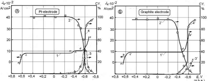
Our polarization studies, compared to the current effi ciency data [4], have demonstrated (Figure 1) that the current effi ciency of the reaction Fe(III)e Fe(II) is close to 100%, while using the Pt electrode under the potentials from +0.6 to (-0.2) ÷(-0.3) V. With further cathode polarization, this value starts to decrease. At the same time, hydrogen emission begins (at Е
0V), which amount is increasing. Consumption of current quantity is thus determined by these two competing processes, up to the potential of metal deposition beginning.In addition to that, certain increase in the current effi ciency value of the reaction Fe(III)e Fe(II) was marked on this electrode, reaching above 100%. The possible reason of this may be catalytic properties of Pt surface, which facilitates the formation of atomic hydrogen, which is a reducing agent with regard to Fe(III) ions. However, the share of this reaction is low, compared to the pure electrochemical reaction Fe(III)e Fe(II), which, according to our estimation, lays within the limits of 5÷7%.
Figure 1. Potential evolution (1, 1’) on platinum (A) and graphite (B) electrodes, and current effi ciency (CY) of the reactions: Fe (III) + е→ Fe(II), (curves 2,2’); 2 Н+ + 2е→Н
2 (curves 3,3’);
Fe(II) - 2е→ Feо (curves 4,4’).
The dependence of current effi ciency of the reaction Fe(III)e Fe(II) from the potential on graphite electrode is decreasing sharply. This is apparently connected with the fact, that on the graphite surface no effect is observed, resulting in iron reducing due to hydrogen, and the current effi ciency of the process Fe(III)e Fe(II) within the potentials area up to the beginning of metal iron deposition, is close to 100%.
With the beginning of metal iron deposition under the potentials (-0.43) ÷ (-0.45)V, the current effi ciency of Fe(III) ions is sharply decreased, remaining only within the limits of several percents, as soon as the basic reaction of Fe(II) ions reduction to metal prevails. The curve of the hydrogen current effi ciency on Pt-electrode passes through the maximum and also decreases to the values of 5÷10 %, as the potentials are shifted to the electronegative area.
Therefore, the succession of the reactions running during the cathode treatment of iron-containing electrolyte within the studied potential area can be presented in the following way. Under the Е
+0.64V, the transition Fe(III)e Fe(II) starts, which occurs with the current effi ciency close to 100%. In the more negative fi eld than Е
0 V, hydrogen emission starts on platinum surface, which begins more and more intensive, up to the beginning of the metal iron deposition. On graphite electrode, unlike the Pt one, hydrogen emission begins much later (under the potential more negative than -0.4V). Presence of the broad area of potentials (about 1V), where the target reaction Fe(III)e Fe(II) runs with the high current effi ciency, close to 100%, testifi es on the possibility of the effi cient application of carbon-graphite three-dimensional electrodes for carrying out of this process in the iron plating electrolytes [5].The work of three-dimensional electrodes is affected at the same time by the number of interconnected factors, specifi cally: the kinetic parameters of the process, hydrodynamic conditions, specifi cs of the CFM applied and other factors, which complicates the study of the electrochemical processes’ regularities. The method of mathematical modeling is one of the effi cient ways to explore the regularities of the three-dimensional electrodes operation [6-8], making it possible to describe the processes occurring within these electrodes. In addition, with the help of this method it becomes possible to predict the changes of the basic technological parameters, infl uencing the studied process, and to optimize the electrolysis conditions.
Electrochemical processes occurring within the studied FTE during the regeneration of iron plating solutions – electroreduction of Fe(III) ions to Fe(II) and Fe(II) ions to metal, are as a rule accompanied by the secondary electrochemical reactions with participation of hydrogen ions and molecular oxygen.
The scope of this work was to create the mathematical models of electrochemical processes occurring within the
fl ow-through three-dimensional electrode during the simultaneous reduction Fe+3→Fe+2 and Fe+2→Fe, considering the electrode reactions of hydrogen and molecular oxygen reduction, as well as the change in the electrode electroconductivity, the electrolyte fl ow rate, concentrations of electroactive substances and other parameters of electrode and electrolyte along the electrode depth. Apart from this, the scope of this work was to carry out the numerical studies of the above electrode processes within the FTE made of the carbon-graphite fi brous materials.
Elaboration of the mathematical model of electrolysis in the polycomponent electrolyte within the FTE
The mass balance within the fl ow of the charged particles involved in the electrode process can be described by the Eq. (1) [9]:
) ) (
( v
i C U grad i FC i i z div t
i ɋ
w w
Here and later zi, Ci (mol/сm3), μ
i – charge, concentration and mobility of i-th electroactive component (i=1,…,4) in the pseudo-homogeneous medium, accordingly; F (C mol-1) – Faraday’s number, grad(U) – gradient of the electric
fi eld potential, v – velocity vector of the electrolyte’s convective transfer, div – vector divergence.
It follows from the equation (1) that the concentration changes within the fl ow are determined by the value of the potential’s gradient U and the electrolyte’s velocity vector v, which do not depend directly on the concentrations and current densities of the partial electrochemical reactions. These functions are determinative with regard to the distribution of electrochemical process within the fl ow-through three-dimensional electrode. In accordance with this point, the mathematical model was proposed, concerning the distribution of polarization, current density and concentrations of substances, involved in the electrode reaction, for the electrochemical systems with two or more electroactive components. Thus, in [10] a mathematical model is proposed of metal electrodeposition on the FTE considering the hydrogen emission reaction:
¸ ¹ · ¨ © § ¸ ¸ ¸ ¹ · ¨ ¨ ¨ © § ( ) ) ( 1 ) ( 1 2 2 x H j x Ɇ j x L x S V S dx U d F
F (2)
) (x M j V S x C zF v w
w , (3) where SV (cm2/cm3) – reaction surface, j
M (А/cm2) – density of polarizing current with regard to metal, jH (А/сm2) – density of polarizing current with regard to hydrogen;
S and
L – specifi c electroconductivity of solid and liquidphases of the system involved, x – coordinate along the electrode depth.
Having transformed the Eq.(1), we shall receive the following system of differential equations for the stationary case: ¦ ¦ w w w w w w 0 ) ( i C i z F x v xi C i z vF xdx dU F
, (4)
Si J F i z V S n i C v w w
. (5) Here JSi (A/сm2) – polarizing current density with regard to the i-th component, n – direction of electrolyte movement, χ (Ω/сm) – a value specifying the electroconducting properties of the system.
The system of Eqs.(4) and (5) can be completed with the polarization kinetic equations [11, 12], linking the values of current densities and potentials at the point x:
i C mi FK i z RT Ri U F i z i i j RT Ri U F i z i RT Ri U F i z i i j x Si J / ) / ) ( exp( 0 1 / ) ( 1 exp / ) (( exp
0 D M
M D M D ¸¸ ¹ · ¨¨ © § ¸ ¹ · ¨ © § ¸ ¹ · ¨ © §
, (6) (where αi - reductive symmetry factor, φRi – equilibrium compromise potential, Kmi – mass transfer coeffi cient, R=8.31 J/molK – universal gas constant), with the initial and boundary conditions applied to the unknown functions:
0 , ) 0 ( ; ) ( ; ) 0 ( i C i C L I L x U S I x U w w w w U
U . (7)
Here I (А/сm2) – overall current density, passing through the electrode, L – depth of FTE.
It is to be noted that the Eq.(5) for the concentration of the second electroactive component (Fe+2) of the studied system Fe(III)/Fe(II)/Fe should be essentially converted, as soon as due to the electrode reaction Fe+3→Fe+2, the concentration of bivalent iron in the electrolyte will be changed with time.
In the studied case of electrolysis running on FTE, the direction of electrolyte fl ow coincides with the direction of current density distribution – х, therefore, the Eq.(5) can be written in the form:
Si J F i z V S dx i dC v
To calculate the changes in the concentration of the fi rst component of electrode reaction (Fe+3), the expression can be written:
dx S J F z V S dC v 1 1 1
i x S J F z v
V S
i x
C '
'
1 1 ) (
1 .
Apparently, the negative increment of trivalent iron concentration at the electrode point xi is equal to the increment of bivalent iron concentration at the same point. Therefore, the differential equation for the bivalent iron concentration from the group (5) can be written in the following form:
i x S J F z v
V S
S J F z v
V S
i x
C '
¸ ¸ ¸
¹ ·
¨ ¨ ¨
© §
'
2 2 1 1 ) (
2 .
In this case the Eq.(5), modeling the Fe+2 concentration distribution on the FTE, will take the following form:
¸ ¸ ¸
¹ ·
¨ ¨ ¨
© §
2
2 1
1 2
z S J
z S J
F V S
dx dC
v .
The system of Eqs. (4) – (7) is enclosed with regard to the unknown functions U(t,x), Ci(t,x), which can be solved by the method described in the work [13], using the algorithms of the distribution calculation of the electrochemical parameters of process and electrode, changing during the electrolysis, specifi cally, electrode electroconductivity, specifi c reaction surface, porosity of CFM, solution fl ow velocity etc. [7,14]. However, during the numerical realization of this model, the essential diffi culties appear, connected with the determination of the compromise potentials φRi and mass transfer coeffi cients Kmi.
In this connection, to perform the calculations, we have chosen the values of the equilibrium compromise potentials φRi from the reference literature available [15] and then have defi ned them more exactly using the method described in the work [16]. Such approach did not cause any diffi culties, as the procedure of values φRi specifying was not resulted in the values which were drastically different from those given in the literature [15].
The essential differences in the calculations results from the experimental data were observed while using the equations of polarization characteristics (6) under the insignifi cant (within 10%) changes in Kmi values.
The exact calculation of mass transfer coeffi cients is complicated, as the appropriate formula:
i b t x M
i b
V m i a t x mi K
¸ ¹ · ¨
©
§
¸ ¹ · ¨ © §
) , ( 0 ) , (
UH U
, (8)
contains ai, bi – constants refl ecting the properties of electrode, electrolyte and hydrodynamic properties of the process, which can be modifi ed within the broad enough limits: 10-3≤a≤ 1.9∙10-2, 0.33≤b≤0.71 [17-21]. In the formula (8) ρ denotes the density of metal deposit, M(x,t) is the amount of the deposited metal within the layer of solitary section in the point х at the time moment t.
It is naturally to suppose that with the suffi cient values of the electrolyte’s fl ow velocity, close to those, really used in practice (0.1≤│v│≤1), the diffusion component of substance transfer towards the carbon-graphite fi bers of CFM electrode will be less signifi cant, than the convection component. This makes it possible to apply the approach, implying the determination of the type of polarization dependence, considering the process hydrodynamics. So, the transfer of i-th electroactive substance within the elementary volume, identifi ed with the point (x) of homogeneous space (Figure 2) is described with the Eq. (9) [13]:
i c div v i Pe i
c ( )
' , (9)
here Δ – Laplace operator, Реi – Peclet number for i-th electroactive component.
Figure 2.The scheme of the elementary volume of FTE, in which the electrolyte fl ows round the cylindrical CFM
At a rough approximation, the Eq.(9) has the following form: 0 2 2 w w w w w i c i Pe w i ɫ
, (10) where w – linear coordinate within the chosen elementary volume,
x i C w i C x i C w i ɫ ) ( ) ( ; i D v ɜ r i
Pe ; Cix– concentration of
i-th component in the point of FTE, which is identifi ed with the selected elementary volume of porous space – point x on the electrode with the depth L, 0≤x≤L, rb- radius of carbon-graphite thread.
The Eq.(10) is complemented with the condition of Ci concentration change on the surface of CFM fi ber, i.e. under w=0 the following equation is applied:
) ( i c iS f iS k w i c w w
. (11) Coeffi cient kiS corresponds to the rate constant of the i-th surface electrochemical reaction, and kiS fiS (ci) – are the dimensionless functions corresponding to the rate of the i-th surface electrochemical reaction, which in the dimensionless form are given by the following formula:
ix C i FD i z i M e i M e i j ɜ r iS k ) 2 1 (
0 ;
RT x p i E x E F i z i i M )) ( ) ( ( 1 D ; RT x ip E x E F i z i i M )) ( ) ( ( ) 1 ( 2 D ; » » » ¼ º « « « ¬ ª 2 1 ) ( 0 )) ( ( i M e i M e ix C w i c i j w c F ; » » ¼ º « « ¬ ª 2 1 0 ) ( i M e i M e i j ix C F ; ) ( )) ( ( ) ( ix C F w i c F c iS f .
The solving of the Eq.(10), on condition (11), has the following form: w i Pe e i A i c
, (12)
with Аi equal to:
ix C i FD i z ɜ r i M e i Pe i M e i M e ix C i FD i z ɜ r i A 1 2 1 » » ¼ º « « ¬ ª
. (13)
Substituting all the values determined into the well-known expression for the polarization curve [5]:
>
@
,lim 0 0 1 2 1 1 ) ( i M i M M i i j e j e e j xj i i i
we shall receive the equation:
>
@
) ( ) ( 1
) (
1 2 1
0 0
x v x FC z e j
e e j x j
i i M i
M M i
i i
i i
, (14)
where ji(х) – current density of the i-th reaction in the electrode point х, jio – exchange current density of i-th reaction,
ji – polarizing current density,
zi – charge of the i-th electroactive component (i=1,…,4), F – Faraday’s number (C mol−1),
D – diffusion coeffi cient, cm2/s,
Ci(x)- concentration of i-th electroactive component (i=1,…,4) in the point х of pseudo-homogeneous space, ν(x) – velocity vector of convection transfer of electrolyte along the axes, or the linear velocity of electrolyte
fl ow,
ra - degree of substance transformation.
The Eq. (14) can be written in another form, if we consider the value
â ix i i i
r C FD z x
j,lim( ) , which in the fi rst approximation refl ects the value of the limited diffusion current:
) ( lim , 1 0
2 1
0 )
(
x i j i M e i j
i Pe
i M e i M e j i Pe
x i j
» »
¼ º
« «
¬ ª
(15)
In this way, the Eq. (14) contains easily determinable dynamic parameters, such as the diffusion coeffi cient, thickness of the diffusion layer, etc., explicitly described by us earlier in [7, 14]. This equation was used for carrying out the numerical calculations.
Numerical calculations of electrolysis on FTE and the discussion of results
As it was already mentioned, the electrochemical processes occurring within the fl ow-through three-dimensional electrodes (FTE) made of the carbon-graphite fi brous materials (CFM) during the electroreduction of Fe(III) to Fe(II) and Fe(II) to metal phase (Fe0), are accompanied with the secondary electrochemical reactions with the involvement of hydrogen ions and molecular oxygen. Therefore, such electrochemical system should be regarded as a polycomponent one, which fl uid phase contains four components that can be involved in the electrode reactions: Fe+3, Fe+2, H+, O
2 [22]. To perform the numerical calculations in accordance with the mathematical model proposed, one needs to know the values of certain physical and kinetic parameters, characterizing the studied system, in which the following reactions can take place: Fe(III)e Fe(II); Fe(II)2e Fe0; 2Н+2e Н
2; О2 2e2H Н2О2 2e2H 2Н2О. The initial values of electrochemical parameters of studied processes were taken from the reference literature [15]. The values of the main parameters and constants used for the numerical calculations are summarized in the Table 1.
Таble 1 Kinetic parameters used for the numerical calculations of electrochemical processes taking place during
the electrolysis of iron-containing electrolyte.
Electrode reaction Reaction parameter, FTE
C0 D j0 α Ep
Fe(III)→ Fe(II) 0.5·10-4 0.5·10-5 0.1·10-3 0.5 0.6
Fe(II)→ Fe 0.5·10-3 0.6·10-5 0.1·10-5 0.43 0.5
2H+ →H
2 – – 0.1·10-5 0.5 0.5
Оаds+2H++2e→H
The process parameters given above, served as a basis for carrying out the computer calculations in accordance with the program elaborated. The results were obtained in a numerical form, and on their base the diagrams were drawn refl ecting the regularities of the electrolysis processes on the CFM. Further on, the calculated values were compared with the experimental data with the scope to estimate their convergence.
In Figures 3-7 the diagrams are presented of the main electrochemical functions distribution within the depth of the FTE for the different values of governing parameters: overall current density J (А/сm2) and input linear fl ow rate of electrolyte u (сm/s), obtained as a result of the numeric calculations.
The analysis of data obtained, presented in Figures 3-7, testifi es that with the increase in the electrolyte fl ow velocity, all the electrochemical reactions studied are shifted to the front side of the FTE (nearest to the counter-electrode). This is the best pronounced under the high densities of the overall current and is insignifi cant under the low current densities.
Figure 3. Potential distribution within the depth of FTE under the different densities of overall current and the electrolyte fl ow velocity: а) – 0.5 сm/s; b) – 1 сm/s.
Current densities, A/cm2: 1 – 0.05, 2 – 0.1, 3 – 0.15; 1’ – 0.1, 2’ – 0.25, 3’ – 0.6.
Figure 4.Current density distribution of the reaction Fe(III)→ Fe(II) within the FTE under the different densities of overall current and the electrolyte fl ow velocity: а) – 0.5 сm/s; b) – 1 сm/s.
Current densities, A/cm2: 1 – 0.06, 2 – 0.1, 3 – 0.15; 1’ – 0.1, 2’ – 0.26, 3’ – 0.5.
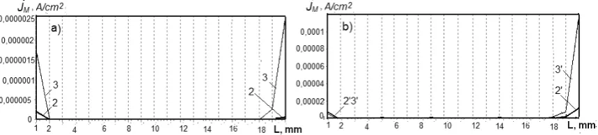
Figure 5. Current density distribution of the reaction Fe(II)→ Fe within the FTE under the different densities of overall current and the electrolyte fl ow velocity: а) – 0.5 сm/s; b) – 1 сm/s.
Figure 6.Current density distribution of the reaction 2H+→H
2 within the FTE under the different
densities of overall current and the electrolyte fl ow velocity: а) – 0.5 сm/s; b) – 1 сm/s. Current densities, A/cm2: 2 – 0.1, 3 – 0.15; 2’ – 0.25, 3’ – 0.6.
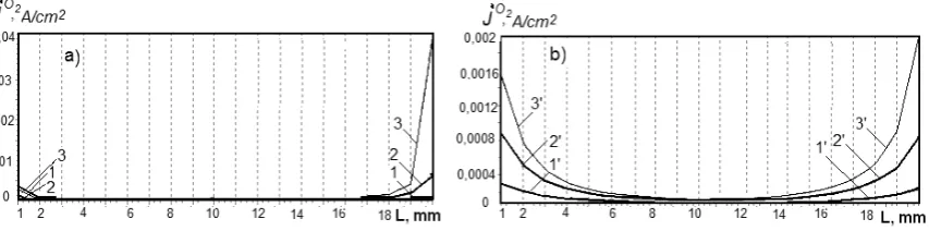
Figure 7.Current density distribution of the molecular oxygen reduction within the FTE under the different densities of overall current and the electrolyte fl ow velocity: а) – 0.5 сm/s; b) – 1 сm/s.
Current densities, A/cm2: 1 – 0.5, 2 – 0.1, 3 – 0.15; 1’ – 0.1, 2’ – 0.25, 3’ – 0.6.
For all the used values of the overall current density, the increase of the electrolyte fl ow velocity causes the increase in the FTE polarization within the entire depth. Thus, under the high values of the electrolyte fl ow velocity the approaching occurs of the potential distributions for various overall current densities. The distribution of the process Fe(III)→ Fe(II) intensity within the electrode thickness (Figure 4) is more uniform under the high values of electrolyte
fl ow velocity and the average values of the overall current density.
Under the high values of the overall current density and the solution fl ow velocity, the processes Fe(II)→Fe and 2H+ →H
2 are localized on the front side of the electrode. Under the less fl ow velocity, both processes take place both on the front and back side of the FTE. It is to be noted, that under the current densities less than 0.1 А/сm2, the processes of bivalent iron reducing to metal and hydrogen emission do not occur.
The partial current density of oxygen reduction reaction is practically symmetrically distributed within the thickness of FTE under the electrolyte fl ow velocity, equal or less than 0.5 сm/s and almost completely is shifted to the frontal side under the fl ow velocity, equal to or higher than 1 сm/s.
Generally, the distribution of electrochemical functions – potential and partial current densities within the electrode depth, is in line with the results of theoretical studies of the processes within the three-dimensional fl ow-through electrodes [23-26], which indirectly confi rms the workability/effi ciency of the mathematical model applied. Conclusions
The application of the mathematical model considered allows to study the cathode reactions connected with the regeneration of the iron plating solutions due to the reaction Fe(III)→ Fe(II), within the fl ow-through three-dimensional electrode. The target reaction is accompanied by the parallel reactions of metal iron deposition, reduction of hydrogen ions and the molecular oxygen.
References
1. Petrov, Yu.N. Effect of electrolysis conditions on iron coatings properties. Tadjikizdat: Dushanbe, 1957, 156 p. (in Russian).
2. Varentsov, V.K.; Covaliova, O.V. Application of carbonic fi brous materials for the reduction of “oxidized” plating iron solutions. Surface Engineering and Applied Electrochemistry. 1988, pp. 55-58 (in Russian).
4. Covaliova, O.V.; Varentsov, V.K. The study of the reduction of rapidly oxidizing iron plating electrolytes on the carbonic fi brous electrodes. Proceedings of Academy of Sciences MSSR, Physico-Technical and Mathematical Series, 1987, 3, pp. 33-37 (in Russian).
5. Damaskin, B.B.; Petrii, O.A. Introduction in Electrochemical Kinetics. Vyschaia Shkola: Moscow. 1975, 275 p. (in Russian).
6. Varentsov, V.K.; Koshev, A.N. Mathematical modeling of electrochemical processes in fl ow-through three-dimensional electrodes. Proceedings of Siberian Branch of Academy Sciences USSR, Chemical Series, 1988, 17, pp. 117-125 (in Russian).
7. Koshev, A.N.; Varentsov, V.K.; Chirkina, M.A.; Kamburg, V.G. Mathematical modeling and the theory of polarization distribution in the electrochemical reactors with fl ow-through three-dimensional cathodes. Mathematical Modeling, 2011, 23(8), pp. 110-126 (in Russian).
8. Koshev, A.N.; Kuzina, V.V. Elaboration and study of mathematical models on non-stationery processes in electrochemical reactors with fl ow-through three-dimensional electrodes. PSUAC: Penza. 2011, 119 p. (in Russian). 9. Newman, J. Electrochemical Systems. Mir: Мoscow. 1977, 463 p. (in Russian).
10. Alkire, R.; Gould, R. Analysis of multiple reaction sequences in fl ow-through porous electrodes. Journal of the Electrochemical Society, 1976, 123(11), pp. 1842-1849.
11. Daniel-Beck, V.S. On the polarization of porous electrodes. 4. Effect of the solid phase resistance on the potential and current distribution in the electrode. Electrochemistry, 1966, 2(6), pp. 672-677 (in Russian).
12. Saleh, M.M. Mathematical modeling of gas evolving fl ow-through porous electrodes. Electrochimica Acta, 1999, 45(6), pp. 959-967.
13. Frumkin, A.N. On the distribution of corrosion process along the pipe length. Journal of Physical Chemistry, 1949, 23, pp. 1477-1482 (in Russian).
14. Kohshev, A.N.; Chirkina, M.A.; Varentsov. V.K. Non-stationery mathematical models of electrochemical processes in the reactors with the fl ow-through three-dimensional electrodes. Electrochemistry, 2007, 43(11), pp. 1372-1378 (in Russian).
15. Sukhotin A.M. Ed. Reference Book on Electrochemistry. Chemistry: Leningrad. 1981, 488 p. (in Russian). 16. Beck, R.Yu.; Zamyatin, A.P. Mass-transfer coeffi cient and surface of the fl ow-through fi brous electrodes, available
for electrolysis. Electrochemistry, 1978, 14(18), pp. 1196-1201 (in Russian).
17. Newman, J.S. Tobias, C.W. Theoretical analysis of current distribution in porous electrodes. Journal of Electrochemical Society, 1962, 109, pp. 1183-1191.
18. Schmal, O., Ercel, J., Van Puin, P. Mass transfer at carbon fi brous electrodes. Journal of Applied Electrochemistry, 1986, 16, pp. 422-430.
19. Beck, R.Yu.; Zamyatin, A.P.; Koshev, A.N.; Poddubny, N.P. Mathematical modeling of the electrolytic deposition of metal within the pores of the fl ow-through three-dimensional electrode. Proceedings of Siberian Branch of Academy Sciences USSR, Chemical Series, 1980, 1(2), pp. 110-125 (in Russian).
20. Doherty, T.; Sunderland, J.G.; Roberts, P.L.; Pickett, D.J. An improved model of potential and current distribution within a fl ow-through porous electrode. Electrochemica Acta, 1996, 41(4), pp. 519-526.
21. Kuzina, V.V.; Zamyatin, A.P.; Koshev, A.N. Мathematical models in the tasks of voltammetric analysis. Ecological systems and equipment. Nauchtechlytizdat: Moscow. 2006, 8, pp. 37-41 (in Russian).
22. Covaliova, O.V. The study of kinetic regularities of Fe(III) ions reduction to Fe(II) in concentrated electrolytes. Studia Universitatis, Natural Sciences Series, 2013, 6(26), pp. 195-203 (in Russian).
23. Varentsov, V.K.; Jerebilov, A.F.; Malei, M.D. Carbonic graphite fi brous materials – new electrodes for metals extraction from the diluted solutions. 1. Nonwoven carbonic graphite fi brous materials. Proceedings of Siberian Branch of Academy Sciences USSR, Chemical Series, 1984, 17(6), pp. 120-127 (in Russian).
24. Koshev, A.N.; Kuzina, V.V. Modeling and calculation of the electroactive component concentration during the electrolysis. Management of Large Systems, IPU RAN: Moscow. 2011, vol. 33, pp. 233-253 (in Russian).
25. Мaslyi, A.I.; Poddubny, N.P.; Medvedev, A.J. The dynamics of metal deposition on the porous electrode with the low initial conductivity under the direct-fl ow regime of electrode operation and high rate of solution fl ow. Electrochemistry, 2006, 42(10), pp. 1237-1244 (in Russian).