Published online February 9, 2015 (http://www.sciencepublishinggroup.com/j/jeee) doi: 10.11648/j.jeee.s.2015030201.26
ISSN: 2329-1613 (Print); ISSN: 2329-1605 (Online)
Cost effective method to locate the vulnerable nodes of
circuits against the electrical fast transients
Behnam Gholamrezazadeh Family, Vahid Hamiyaty Vaghef, Maryam Shabro
Communication Department, Niroo Research Institute, Tehran, Iran
Email address:
[email protected] (B.G. Family), [email protected] (V. H. Vaghef), [email protected] (M. Shabro)
To cite this article:
Behnam Gholamrezazadeh Family, Vahid Hamiyaty Vaghef, Maryam Shabro. Cost Effective Method to Locate the Vulnerable Nodes of Circuits Against the Electrical Fast Transients. Journal of Electrical and Electronic Engineering. Special Issue: Research and Practices in Electrical and Electronic Engineering in Developing Countries. Vol. 3, No. 2-1, 2015, pp. 72-77. doi: 10.11648/j.jeee.s.2015030201.26
Abstract:
Electrical Fast Transients (EFT) pulses may cause a large number of circuits to fail. Switching power supplies, inductors, contact relays, and high voltage switches electrically or electromagnetically strike the data, address and control lines of processors, memory elements, or even analog parts and leads to soft or permanent errors. In general, compliant test is accomplished to address the susceptibility of circuits to EFT pulses. However, extremely high cost of these tests encounters the compliant test with difficulty. As a result, in this paper a low-cost EFT simulator circuit is proposed to locate the vulnerable parts of the circuit. The approach is easily applicable to any point of any circuit. The design is performed such that the proposed circuit does not damage the Equipment Under Test (EUT). Experimental results show that the proposed approach effectively detects the vulnerable circuits and practically has been used at the design phase of the DTPS-8C device.Keywords:
Electromagnetic Compatibility, EFT/B, Switching, Protection Devices1. Introduction
Interaction between several electronic equipments significantly increases the vulnerability of current electric equipments. Thus, electromagnetic compatibility (EMC) is an important requirement to achieve the reliable operation.
EMC is defined as the proper function of equipment in its electromagnetic environment without introducing intolerable disturbances to neighbor equipment. On the other hand, immunity is defined as the ability of a device, equipment or system to work without performance degradation at the presence of an electromagnetic disturbance. Electrical Fast Transient/ Burst (EFT/B) is a major test to measure the immunity of equipments, as described in IEC 61000-4-4 (2012).
For industrial devices, taking all guidelines in hardware and software components into account is an essential step. EMI reduction and EMC improvement will be achieved using protection devices such as shields, grounding, filters, isolators, chocks, ferrite beads, varistors, transient voltage suppressors (TVS) and proper PCB layout design[2]. Typical EFT/B failures are due to an inadequate or unavailable interface for ground reference. Therefore, designers should try to use appropriate ground reference and protection at the incoming
or outgoing ports. In addition, to achieve less susceptible systems to EFT pulses, the software layer should be taken into account. Software problems include the data loss, system malfunction, retrieving an incorrect data stored in memory, or executing an incorrect portion of the memory. Software should design to detect and correct errors before a device failure. Reading the critical inputs several times, verifying the data contents, counters, and pointers, using serial protocols instead of parallel ones, watchdog timers, etc are useful approaches to avoid software malfunction.
Journal of Electrical and Electronic Engineering 2015; 3(2-1): 72-77 73
the use of simulations during the system and board design phases is recommended for extracting the critical points.
This paper presents a simple and inexpensive way for detecting the critical parts of a circuit with respect to EFT/B pulses, as a fundamental evaluation of the system. The proposed method is low-cost while it benefits from non-destructivity and easy application to internal nodes of the EUT. Thus, it reduces the cost of reliable design significantly.
The remainder of the paper organizes as follows. The electrical fast transient pulses are described in section 2. The EFT pulse generator is proposed in section 3 and the conclusion is presented in section 4.
2. Electrical Fast Transients/ Burst
The EFT/B test aims to simulate the disturbances created by a ‘showering arc’ at the contacts of an ordinary AC mains switch or relay contacts as it opens. This test evaluates the immunity of electrical and electronic equipment when subjected to EFT/B on supply, signal, control and earth ports. This phenomenon is modeled as Fig. 1. The characteristic of burst generator, test setup, test verification, and test procedure are described in IEC 61000-4-4 standard. It has fast rise time, low energy, high voltage, and consists of a single unidirectional impulse repeated at a 5kHz(100kHz) in bursts lasting 15(0.75) milliseconds each, with three bursts per second. Different voltage test levels are defined in standard as Table 1. The test severity level and frequency are selected according the equipment installation environment.
3. Design and Implementation of a Cost
Effective EFT Pulse Generator
The simplified circuit diagram of the EFT/B generator is given in Fig. 2. In this circuit, a high voltage source charges a Cc capacitor and the charging and discharging of capacitors is controlled by a Switch. The desired pattern is produced, as shown in Fig. 1.
Figure 1. Representation of an EFT/B according to IEC 61000-4-4 [1].
Figure 2. Simplified circuit diagram of an EFT/B according to IEC 61000-4-4.
Table 1. Test voltage and repetition frequency of the impulses according to IEC 61000-4-4 [1].
Signal and control ports Power ports, earth port (PE)
Level Repetition
frequency kHz Voltage peak kV Repetition frequency kHz Voltage peak kV
5 or 100 0.25
5 or 100 0.5
1
5 or 100 0.5
5 or 100 1
2
5 or 100 1
5 or 100 2
3
5 or 100 2
5 or 100 4 4 special special special special X
The use of 5kHz repetition frequency is traditional; however, 100kHz is closer to reality. Product committees should determine which frequencies are relevant for specific products or product types.
"X" can be any level, above, below or in between the others. The level shall be is in specified in the dedicated equipment specification.
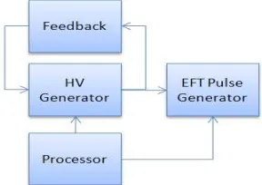
This study explains the design and implementation of an EFT pulse generator in order to determine the critical nodes of an electronic circuit. The block diagram of the proposed circuit is shown in Fig. 3.
Figure 3. Block diagram of the designed EFT/B generator
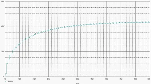
Figure 5. Output voltage of Fig 4.
As mentioned before, a high voltage circuit is required to produce EFT pulses [4]. Since these pulses have high voltage with low energy, the low-cost circuit in Fig. 4 is proposed to meet the requirements. The output voltage of this circuit is simulated by HSPICE software as shown in Fig. 5. This graph shows the voltage across the C1 capacitor. This circuit produces voltages higher than 400 V in less than 50ms. The main advantage of this circuit is its ability to generate high voltages using a voltage of 12 V. This makes the circuit portable. The power consumption of the circuit is also significantly low. The portability of this circuit allows users to test different parts of a large system easily.
To generate higher voltages, MOSFET transistors with higher breakdown voltages can be used. For example: FS10SM (with 800V breakdown) or IXZR08N120B (with 1200V breakdown).
To control the output voltage variations due to the load, the output voltage is sampled and accordingly varies the input frequency or duty cycle of the square wave. The efficiency of this circuit is low; however, using the feedback circuit shown in Fig. 6 the output voltage is controlled with higher efficiency.
Using the feedback circuit, the output voltage varies according to the input pulse shape which prevents excessive output voltage. The output voltage level is set by R14, R15 and the Zener diode D2. Several voltage levels can be selected using this circuit.
A simple circuit shown in Fig. 7 is used to generate the EFT pulses. The transistor pulsed on and off simultaneously with input pulses and discharges of high voltage stored in the C2 capacitor in the minimum possible time. The output of the
circuit is shown in Fig. 8. This output can be applied to the EUT using another capacitor.
Figure 6. Feedback for voltage control.
Journal of Electrical and Electronic Engineering 2015; 3(2-1): 72-77 75
Figure 8. EFT pulses of Fig 7.
Figure 9. Series of avalanche transistors.
Figure 11. Designed EFT generator board.
The output pulses generated by this circuit are not fully compatible to the pulses described in the standard IEC61000-4-4 because of the capacitor's internal series resistance and the transistor's on delay time. But they can reveal the sensitive parts of the circuit under testing to standard EFT pulses.
It is also possible to use avalanche transistors connected in series and operated close to their avalanche breakdown as shown in Fig. 9 for switching very high voltage pulses [5]. For example, a ZTX415 transistor is suitable for this purpose.
In order to generate the input pulse for switching a MOSFET transistor, a microcontroller is used. The microcontroller output pin must be isolated from a high voltage generator; otherwise the distortion produced by this circuit prevents the proper operation of the microcontroller. Figures 10 and 11 show the schematic and layout of the designed circuit and the EFT pulses generated by this simulator are shown in Fig. 12 and Fig. 13. The impulses are repeated at 5 kHz in bursts which each one lasts 15ms and the period of bursts is 300ms.
Figure 12. EFT pulses generated by simulator.
Figure 13. Waveform of a single burst.
According to IEC 61000-4-4 the EFT pulse is applied with a coupling network to the power ports and with a coupling clamp to input/output cables of the EUT. Due to the use of protective components in these ports, the amount of EFT/B pulses energy will decrease. Therefore, if the output of the proposed method with lower voltage than the standard EFT/B pulses is applied to the internal nodes of the circuit under testing, it approximately simulates the effect of a standard EFT/B pulse. Therefore, the sensitive parts of the circuit under test are easily identified using this method. Due to the lower energy of the proposed circuit, it is directly applicable to all components on the circuit during its normal operation while the circuit reaction is studying.
4. Discussion and Conclusion
Journal of Electrical and Electronic Engineering 2015; 3(2-1): 72-77 77
effectiveness. Furthermore, the proposed approach is non-destructive and easily applicable to internal node of the EUT.
Acknowledgements
This work was supported by the Niroo Research Institute (NRI), Iran and PKG under Grant No. JCMPN02.
References
[1] IEC61000-4-4, "Electromagnetic compatibility (EMC), Part 4-4: Testing & measurement techniques – Electrical fast transient/ Burst immunity test", edition 3.0, 2012.
[2] J. R. Barnes, "Designing Electronic Systems for ESD Immunity", Conformity magazine, Feb. 2003. Online at: http://www.dbicorporation.com/esd-art3.pdf.
[3] S. Hyung, J. Young, "Analysis of Coupling Mechanism and Solution for EFT Noise on Semiconductor Device Level", Proceedings of the International Conference on Electromagnetic Interference and Compatibility, New Delhi, India, 6-8 Dec. 1999.
[4] E. Rogers, "Understanding Boost Power Stages in Switch mode Power Supplies", Application Report, Mixed Signal Products, TI Literature Number SLVA061, 1999. Online at: http://www.ti.com/lit/an/slva061/slva061.pdf.
[5] A. Tamuri, "Nanoseconds Switching for High Voltage Circuit Using Avalanche Transistors", Applied physics research, Vol. 1,
No. 2, 2009. Online at:
http://www.ccsenet.org/journal/index.php/apr/article/viewFile/ 3287/3601.