This paper presents an optimization method to optimize the parameters of the Microgrid controller in islanding mode. The controller optimal parameters have been obtained by using the particle swarm optimization (PSO). This is done based on minimization of the errors in the current and voltage controllers. Finally, simulation has been carried out to verify the effectiveness of the optimized controller. Stability analysis of the controller is verified using classical approach.
A B S T R A C T ARTICLE INFO Keywords: Distributed Generation Microgrid Islanding Droop Control Power Sharing PSO Article history:
Received January. 11, 2018 Accepted May. 1, 2018
I. INTRODUCTION
Microgrid is defined as a controllable unit which con-sists of Distributed Generations (DG), loads, energy stor-ages and control devices1,2. Microgrid has two
opera-tion modes including grid connected mode and islanding mode. In grid connected mode, voltage and frequency of microgrid is controlled by main grid and DGs supply total or part of the loads. In the islanding mode, the microgrid is disconnected from main grid because of a fault or a preplanned switching in connecting line. In this mode, DGs should satisfy the power demand of sen-sitive loads in microgrid. Since the only generation units in an islanded microgrid are existing DG units which usu-ally are from several types. Consequently besides feeding total loads, voltage and frequency of microgrid should be controlled by these DG units. Hence, the microgrid could supply high power quality and reliability to customers.
a)[email protected], [email protected], Tel: +98-11-425-66191, Fax: +98-11-425-66190, Department of Electri-cal Engineering, Jouybar Branch, Islamic Azad University, Jouy-bar, Iran
http://dx.doi.org/10.22111/ieco.2018.24354.1022
Controlling microgrid in both operation modes has been presented3–8. Controller of islanded microgrid has three parts. First part is power controller. It is based on the droop technique to share active and reactive powers with other DGs. The other parts include voltage and cur-rent controllers that use PI controller for their purpose.
Tuning of the controller parameters is very important to achieve the system stability and have a good perfor-mance against load variations. The main problems for controller parameter optimization are nonlinearity and complexity of the system. Small signal linearization is a usual method for designing of controller parameters3–5.
But this method depends on the operation point9. Computational intelligence algorithms such as Ge-netic Algorithm (GA) and Particle Swarm Optimization (PSO) have been used to solve problems of the power system. However, some deficiencies in GA performance such as the premature convergence have been recorded. On the other hand, PSO has been widely implemented and stamped as one of the promising optimization tech-nique due to its simplicity, computational efficiency, and robustness10,11. PSO is a population based search
tech-nique deriving from models of insect swarm or avian flock behavior during food search12. So parameters of the PI controllers are obtained using particle swarm optimiza-tion (PSO) in this paper.
In this paper, an optimization approach is used to op-timize the parameters of the microgrid controller in is-landing mode. First, this controller is introduced in de-tail. Then, a PSO based optimization is proposed to design PI coefficients of voltage and current controllers. The effectiveness of the proposed optimal controller un-der load variation has been tested through the simula-tions in MATLAB/Simulink. Finally, the stability of the controllers with optimized parameters is analyzed using classical control approach. The results show that the pro-posed optimization method is useful for performance of the microgrid.
II. CONTROL STRATEGY
FIG. 1. DG controller in islanding mode.
Active and reactive powers of DG are calculated using the measured output voltage and current. Power con-troller determines DGs output voltage (magnitude and frequency) for active and reactive powers based on the droop characteristics. Then, the voltage and current controllers are designed to reject high-frequency distur-bances and provide sufficient damping for the LC filter13.
A. Power Controller
The basic idea behind the droop control is to mimic the governor of synchronous generator. In a conventional power system, synchronous generators will share any in-crease in the load by decreasing the frequency accord-ing to their governor droop characteristic. This principle is implemented in inverters by decreasing the reference frequency when there is an increase in the load. Sim-ilarly, reactive power is shared by introducing a droop characteristic in the voltage magnitude13. In islanding
operation, droop method can be used to share loads and controlling voltage and frequency in special range.
Two coefficients control the change slope of frequency and voltage against active and reactive power.
W =Wn−mP (1)
V =Vn−nQ (2)
where Wn, Vn, m, n, P, Q are rated frequency, rated
voltage, active power droop coefficient, reactive power droop coefficients, output active power and output reac-tive power and rated acreac-tive power of DG, respecreac-tively.
Droop coefficients are defined below:
m= ∆w
Pmax
(3)
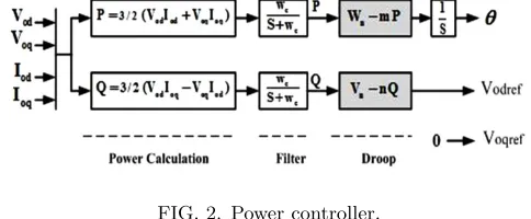
FIG. 2. Power controller.
n= ∆V
Qmax
(4)
where ∆W and ∆V are maximum allowable deviation of frequency and voltages. AlsoPmax andQmax are
maxi-mum output active and reactive powers of DG. Fig. 2
shows the power control in details. First the instan-taneous output active and reactive powers the DG are calculated using measuring output current and voltage. Following equations show this calculation.
P = 3
2(VodIod+VoqIoq) (5)
Q= 3
2(VodIoq+VoqIod) (6) These calculated instantaneous powers are passed through a low pass filter to remove the fluctuations. Cut of frequency of this filter (wc) is assumed to be 10% of
nominal frequency.
The outputs of droop control are voltage magnitude and angular frequency which define the reference angle of the voltage using an integrator. The control strategy is chosen such that the output voltage magnitude reference is aligned to thed-axis of the inverter reference frame, and theq-axis reference is set to zero14.
B. Voltage Controller
By using Kirchhoff law in Fig. 1, following equations are yields.
iabc=iC+ioabc (7)
iC=Cf(
dvo
dt ) (8)
Applying parks transformation to above equation:
id=iCd+iod (9)
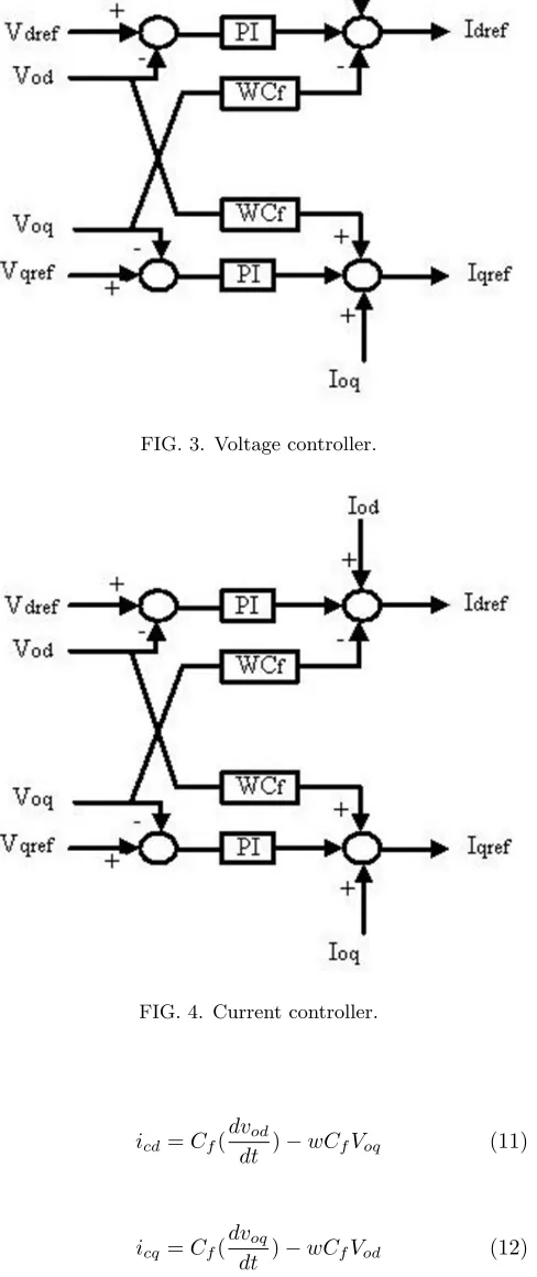
FIG. 3. Voltage controller.
FIG. 4. Current controller.
icd=Cf(
dvod
dt )−wCfVoq (11)
icq=Cf(
dvoq
dt )−wCfVod (12)
To provide close voltage regulation, output voltage con-troller is adopted.
Fig. 3 shows the voltage controller. The controller employs PI regulator to generate the reference current.
S
where KP V and KIV are the proportional and integral
gains of PI controller, respectively. Cf is the filter
capac-itance.
C. Current Controller
By using Kirchhoff law in Fig. 1
Vabc=Voabc+Lf(
diabc
dt ) (15)
Applying parks transformation
Vd=Vod+Lf(
did
dt)−wLfiq (16)
Vq=Voq+Lf(
diq
dt )−wLfid (17)
After controlling voltage and defining the current refer-ence, the current controller will follow its reference. The current controller employ PI regulator for current regu-lation.
Dynamic of the current controller can be given by
Vd= (KP I+
KII
S (Idref−Id)−wLfIq+Vod (18)
Vq= (KP I+
KII
S (Iqref−Iq)−wLfId+Voq (19)
whereKP I,KII are the proportional and integral gains
and Lf is filter inductance. Fig. 4 shows the current
controller.
III. OPTIMIZATION ALGORITHM
A. Particle Swarm Optimization Theory
Particle swarm optimization (PSO) is a population-based stochastic optimization method12. It is a
FIG. 5. Optimization of current and voltage controllers.
of remembering the best position in the search space it visited15.
B. Control Objective
For enhancement of microgrid performance, coeffi-cients of PI in voltage and current controllers must be optimized. The designing procedure is presented as fol-lows.
Objective Function: In islanding mode, the optimiza-tion parameters are KP V, KIV, KP I and KII. In this
mode, the goal of optimization is to minimize the error of the voltage and current, as presented in Fig. 5.
Limitation of Problem:In islanding mode of operation, the problem limits are:
KP Vmin< KP V (20)
KIVmin< KIV (21)
KP Vmin< KP V (22)
KP Imin< KP I (23)
KP V andKIV are the voltage controller proportional and
integral gains, respectively. AlsoKP V andKP I are
pro-portional coefficients of voltage and current controllers, respectively.
In this paper, minimum limits of all coefficients are set to zero. According to above, the optimization problem can be formulated as:
M in(Error) (24)
Subject to limits as given in (20)-(23).
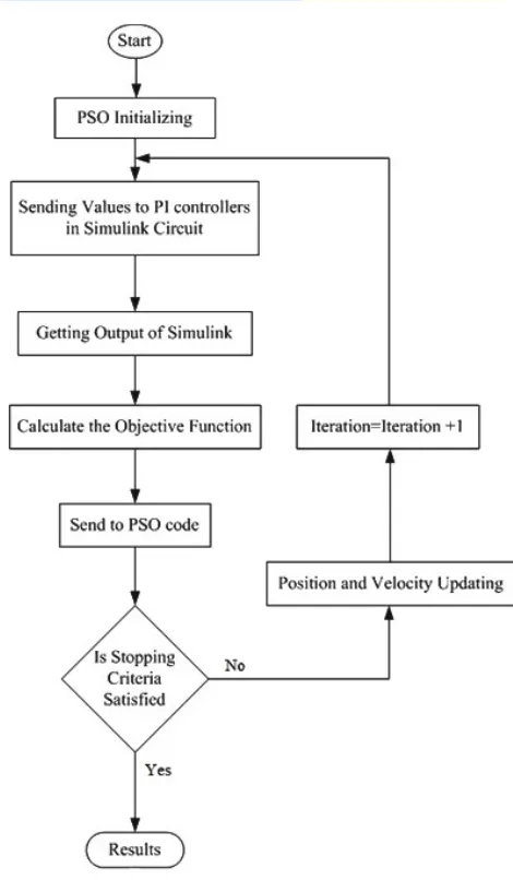
FIG. 6. Flowchart of the optimization scheme.
TABLE I. PSO parameters
Swarm Size 20
Number of Generation or Iteration 300 Acceleration Constant C1=C2= 2
Wstart 0.95
Wend 0.4
C. Implementation of PSO based Optimization
Fig. 6 shows the flow chart of the PSO-based opti-mization scheme that proposed in this paper. This was executed using codes in MATLAB software.
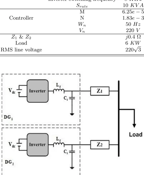
M 6.25e−5
Controller N 1.83e−3
Wn 50Hz Vn 220V
Z1 &Z2 j0.4 Ω
Load 6KW
RMS line voltage 220√3
FIG. 7. System configuration.
IV. SIMULATION
A. System Configuration
A microgrid with two DG is shown in Fig. 7. System parameters are presented in Table II. For verifying the power sharing between DGs, load is changes from 6kW
to 10kW att= 0.4s.
It should be noted that for determining droop coeffi-cients in Table II, maximum frequency deviation (∆f) and maximum voltage deviation (∆V) are considered to 0.5Hzand 5%, respectively.
TABLE III. Result of optimization
KP V KIV KP I KII PSO 0.32987 39.962 1.0926 656.58
FIG. 8. Convergence of the objective function for the pro-posed PSO technique.
FIG. 9. Output powers of DGs.
B. Optimal Values
Table IIIshows the results of optimization.
Convergence of the objective function for the proposed PSO optimization technique is shown in Fig. 8. It can be seen that the PSO converge has a fast rate.
C. Simulation Results
Simulation outputs with the optimal values are pre-sented below. According to figures9 and 10, following results can be yields:
1. Power is shared between DG units correctly.
2. Frequency deviation is in the allowable range.
3. It can be seen that the DGs follow load change quickly and overshoot is minimized.
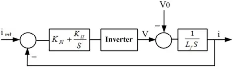
FIG. 11. Block diagram of current controller.
4. It is clear that the system has appropriate transient responses.
As a result, the microgrid has a good response and per-formance with the optimized controller.
V. STABILITY ANALYSIS
In this section, stability of voltage and current con-trollers with optimized PI gains are verified. For this purpose, their transfer functions should be determined.
A. Current Control Transfer Function
Fig. 11 shows the block diagram of the current con-troller for islanding operation. V0 is the disturbance
in-put. The inverter stage does not have any significant transient time associated with it16, and hence, it
mod-eled as an ideal gain. This ideal gain can be given by
Gin(s) = 1. Block diagram of current controller is shown
in Fig. 11.
The transfer function of the current controller is given by (25). It can be seen from (25) that the system is stable based on the conventional control theory.
T(S) = 1.3123S+ 309.08
1.35×10⁻³S+ 1.3123S+ 309.08 (25)
Fig. 12Shows bode plot of the current controller. It can be seen that the system have positive phase margin and is stable. Fig. 13shows step response of the controller. In Fig. 13, Rise time (tr) is 0.00151, Overshoot is 13.3%
and steady state error is zero. We can find out that the system has appropriate performance.
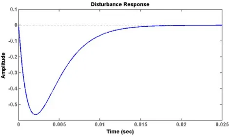
For analysis response of current controller to distur-bance, the unit step is applied to disturbance input (V0)
in Fig. 14. It can be seen that the system have good response and disturbance is damped very soon. Settling time is less than 15ms.
B. Voltage Control Transfer Function
Block diagram of voltage controller is shown in Fig. 15. The transfer function of this controller system is given by (26). According to (26), the system is stable based on the conventional control theory.
T(S) = 4.511S
2+ 3438S+ 491676
6.75×10⁻⁸S4+ 5.25×10⁻⁴S3+ 4.811S2+ 3438S+ 491676 (26)
Fig. 16Shows bode plot of the voltage controller. It can be seen that the system have positive phase margin and is stable. Fig. 17 shows step response of the controller. In Fig. 17, settling time (ts) is 0.00144, Overshoot is 24%
and steady state error is zero. We can find out that the system has appropriate performance. For analysis the re-sponse of voltage controller to disturbance, the unit step is applied to disturbance input (io) in Fig. 18. It can be
seen that the system have good response and disturbance is damped very soon. Settling time is less than 19ms.
VI. CONCLUSION
This paper introduces a controller for controlling distributed generation resources of the microgrid in is-landing operation mode. Optimization method was used to select the optimal parameters of this controller. Case study and PSO algorithm that has the task of finding the optimal solutions during the search were implemented in MATLAB software. Simulation results show that the
power is shared between DG units correctly. Also, these results prove that parameters optimization are correct and system responses are good. Stability analysis was performed with optimized parameters. The results obtained in this study once again highlight the need for proper selection of control coefficients. Because incorrect selection may lead to oscillatory and undesirable system responses.
REFERENCES
1N. Hatziargyriou, et al., “Microgrids,”Power and Energy Maga-zine, IEEE, Vol. 5, pp. 78-94, 2007.
2R. H. Lasseter, “Certs Microgrid,”in System of Systems
Engi-neering, 2007. SoSE ’07.IEEE International Conference on, pp. 1-5, 2007.
3N. Pogaku, M. Prodanovic’, and T. Green, “Modeling analysis and testing of autonomous operation of an inverter-based micro-grid,”IEEE Transactions on Power Electronics, Vol. 22, No. 2, pp. 613-624, Mar. 2007.
FIG. 12. Bode diagram of current controller.
FIG. 13. Step response of current controller.
FIG. 14. Disturbance response of current controller.
FIG. 15. Block diagram of voltage controller.
FIG. 16. Block diagram of voltage controller.
FIG. 17. Step response of voltage controller.
interfaced distributed resources,”IET Generation Transmission
&Distribution, Vol. 1, No. 3, pp. 369-378, May. 2007.
5K. Sao and P. W. Lehn, “Control and power management of converter fed microgrids,”IEEE Transactions on Power Systems, Vol. 23, No. 3, pp. 1088-1098, Aug. 2008.
6F. Katiraei and M. Iravani, “Power management strategies
for microgrid with multiple distributed generation units,”IEEE Transactions on Power Systems, Vol. 21, No. 4, pp. 1821-1831,
Nov. 2006.
7E. Barklund, N. Pogaku, M. Prodanovic’, C. Hernandez-Aramburo, and T. Green, “Energy management in autonomous microgrid using stability constrained droop control of invert-ers,”IEEE Transactions on Power Electronics, Vol. 23, No. 5, pp. 2346-2352, Sep. 2008.
8Y. Mohamed and E. El-Saadany, “Adaptive decentralized droop controller to preserve power sharing stability of paralleled invert-ers in distributed generation microgrids,”IEEE Transactions on Power Electronics, Vol. 23, No. 6, pp. 2806-2816, Nov. 2008. 9Il-Yop Chung, Wenxin Liu, David A. Cartes, Emmanuel G.
Collins, Jr, and Seung-Il Moon “Control Methods of Inverter-Interfaced Distributed Generators in a Microgrid System”IEEE Transactions on Industry Applications, Vol. 46, No. 3, May/June 2010.
10B. Panigrahi, A. Abraham, and S. Das Eds, Computational In-telligence in Power Engineering. Berlin, Germany: Springer-Verlag, 2010.
11M.A. Hassan and A. Abido, “Optimal design of microgrid in autonomous and grid-connected modes using particle swarm op-timization,”IEEE Transactions on Power Electronics, Vol. 26, No. 3, Mar. 2011.
12J. Kennedy and R. Eberhart, “Particle swarm optimization,”in Proc. IEEE International Conference on Neural Networks, Perth, Australia, Vol. 4, pp. 1942-1948, 1995.
13N. Pogaku, M. Prodanovic , and T. Green, “Modeling analysis and testing of autonomous operation of an inverter-based micro-grid,”IEEE Transactions on Power Electronics, Vol. 22, No. 2, pp. 613-624, Mar. 2007.
14Y. Mohamed and E. F. El-Saadany, “Adaptive Decentralized
Droop Controller to Preserve Power Sharing Stability of Par-alleled Inverters in Distributed Generation Microgrids,”IEEE Transactions on Power Electronics, Vol. 23, pp. 2806-2816, 2008. 15M. Peyvandi, M. Zafarani and E.Nasr, “Comparison of
Parti-cle swarm optimization and the Genetic Algorithm in the im-provement of power system stability by an SSSC-based con-troller,”Journal of Electrical Engineering &Technology, Vol. 6, No 2, pp. 182-191, 2011.
16I. J. Balaguer, Q. Lei, S. Yang, U. Supatti, and F. Z. Peng,
“Control for Grid-Connected and Intentional Islanding Opera-tions of Distributed Power Generation,”IEEE Transactions on Industrial Electronics, Vol. 58, No. 1, Jan. 2011.
Mehrdad Ahmadi Kamarposhti was born in