Vol.9 (2019) No. 4
ISSN: 2088-5334
Application Design of Farmbot based on Internet of Things (IoT)
Bagus Murdyantoro, Denny Sukma Eka Atmaja, Haris Rachmat
School of Industrial and System Engineering, Telkom University, Jl. Telekomunikasi Terusan Buah Batu, Bandung, 40257, Indonesia E-mail: [email protected]
Abstract— The agribusiness sector is the largest economic sector and the most important part of the Indonesian national economy,
but the agribusiness sector begins to experience threats in fulfilling human food. Fulfillment of food faced some challenges including an increase in population, which means rising food, urbanization resulting in a decrease in the number of farmers and dietary changes, limited resources (land and air), changes to facilitate and waste food. This corresponds to the data issued by the United Nations, which is the fulfillment of food from approximately 9.6 billion people in the world in 2050 [2]. Along with that, the agricultural land area also decreased due to the transfer of agricultural land function. Farmbot can increase agricultural production to solve human food because it can manage crops within 24 hours without stopping. Farmbot is liquid of agricultural robots that can plant seeds with regular, watering plants and monitoring plant growth. Farmbot can be controlled through an application interface that allows remote access from any location in easy Internet-connected devices. In this study, it will create an automation system that can plant seeds, watering agricultural crops by controlling air production, monitoring plant conditions, plant databases by using applications and designing algorithms to detect crops. Besides, other ways can measure the moisture of the soil to scheduling watering as a watering parameter. To implement this feature can work using a robotic hand with a CNC (Computer Numeric Control) gesture system that would be controlled by the Arduino and Raspberry PI. Following are the procedures for implementing agricultural automation with IoT applications (Internet of Things), seedlings with the help of seeders that stored in plant databases, watering and direct monitoring by users who use camera help.
Keywords— farmbot; precision agriculture; internet of things; automation.
I. INTRODUCTION
Food needs is one of the main needs in human life. As the world's high population, food becomes a vital commodity and the attention of many countries. Agriculture is one of the crucial sectors in preparing this food security [1]. The agricultural sector is facing a major challenge to meet the food needs of approximately 9.6 billion people in the world in 2050 as predicted by the United Nations, which publishes a projected data on the number of world population Based on data gathered up to the year 2012 [2]. Food Fulfillment faced several other challenges, namely urbanization, which resulted in a decline in farmer numbers and dietary changes, resource limitations (land and water), climate change, and food waste. On the other hand, data from the census of Agriculture in 2013 showed significant changes in the number of farmer families in Indonesia. In 2003, the total family of farmers was 31 million families. While in 2013, the number decreased to 26 million families. The average decline is 1.75% per year; this is due to the number of farmers who switched to other jobs [3]. Along with that, agricultural land area also decreased due to the transfer of land function. Based on data of the Ministry of Agrarian and Spatial/National Defense Agency stated that the function of
paddy fields to non-paddy fields reaches 150-200 thousand hectares annually [4]. This of course not only happens in Indonesia, but it is a global phenomenon. To be able to provide food continuously for the entire population, the agricultural industry can be accelerated by embracing the IoT. This is increasingly important given the challenges to the limitations of agricultural land, weather changes and the increase in environmental impact due to intensive farming practices adds barriers to world food provision.
hardware. In the application, the hardware is backed by the adoption of high-speed Internet access, mobile devices, and low-cost satellites that are reliable for imaging and positioning [6]. The main purpose of the technology implementation is to optimize the increase of yield (quality and quantity) and efficiency of resource usage. One of the fundamental implementations of Agriculture is the site-specific management (SSM). SSM is the management of agricultural plants on a smaller scale than in general. SSM utilizes a wide range of sensors, remote sensing, and other technologies to support agriculture. This is especially useful for doing the right actions, at the right place, and in a good time [7]. A real form of SSM one of them is Farmbot, an agricultural machine tool consisting of a robot that can move according to the given coordinates, equipped with a user interface to determine crop and planting location, and agricultural data to Optimizing the farm. In this study will be designed the Farmbot application which is based on the Internet of Things (IoT) which can make it easier for users to do planting, watering plants regularly and monitor the development of plants that have been planted with Using an application that allows remote access from any location and any device by using the Internet.
II. MATERIALS AND METHOD
A. Materials
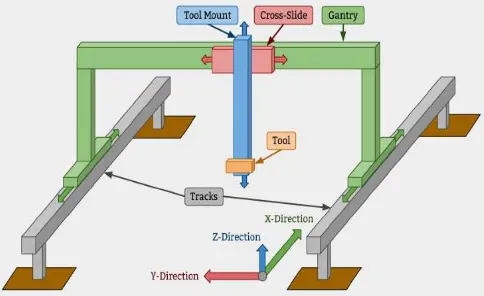
Farmbot is an open-source CNC farming machine and software package designed for small-scale precision food production. Similar to 3D printers and CNC milling machines, FarmBot hardware employs linear guides in the X, Y, and Z directions, see Fig 1. This allows for tooling such as seed injectors, watering nozzles, sensors, and weed removal tools to be precisely positioned and used on the plants and soil. An Arduino/RAMPS stack controls FarmBot and an internet connected Raspberry Pi 3. The hardware is designed to be simple, scalable, hackable, and easily produced. Using the web application, the user can graphically design their farm or garden to their desired specifications and synchronize the numerical control code with the hardware. Other features include storing and manipulating data maps, a decision support system to facilitate data driven design, access to an open plant data repository, and real-time control and logging.
Fig 1 High Level Cartesian FarmBot Design
Farmbot, which is identified via the Web application, enables remote access from any location and any device using the Internet. The Farmbot garden Area can be easily customized and designed using a Web-based interface named with the Farmbot Web application. Fig 2 is a Farmbot Web application allowing users to easily configure and control farmbots from Web browsers on laptops, smartphones, and more. The app has a real-time manual control and logging, making sequences of activities according to the user's desire to be run by Farmbot, and users can design and manage the farm graphically with drag and drop to design the garden. MQTT Gateway is a cloud application that acts as an intermediary for all the commands between Web application Farmbot and Farmbot devices. The Message Broker handles socket connections, device identification, and authentication. Raspberry Pi uses a special operating system named Farmbot OS to maintain the connection and synchronize with the Web application through the message broker and MQTT Gateway. It allows farmbots to download and run scheduled, real-time, controlled events, and upload logs and sensor data. Farmbot OS communicates with the Arduino via USB to send and receive G-code command data. Farmbot OS has a built-in utility called Configurator that allows users to perform WiFi settings from WiFi devices such as laptops or smartphones. Farmbot Arduino firmware is a software that is installed to the Farmbot microcontroller that is the Arduino Mega 2560 and has the ability to operate hardware, tools, sensors, and other electronic farmbots. Farmbot Arduino firmware can receive G and F codes from Raspberry Pi via USB serial connection such as to move the motor, read and write pins that correspond to the user's wishes, transmit the collected data from the rotary encoders and read Pin to be informed to Raspberry Pi.
Fig 2 Farmbot Web-based Interface
B. Method
Fig 3 below describes a frame of mind that consists of a sequence of problems dealt with in making this research with a conceptual concept that will make it easier for writers to carry out the research process from the beginning to completion.
Fig 3 Conceptual Model
conducted by specifying the function specifications of the Farmbot to be created and determine the hardware and software to be used in this research. Then, it was proceed with system design and implemented as well as tested. In the design process, this system implemented and tested to obtained results and feedback from this research.
III.RESULT AND DISCUSSION
A. Farmboat Features and Category
Farmbot App is an application that is based on Internet of Things used as controlling, monitoring and scheduling such as for planting, and watering crops by utilizing the Internet through a computer. The controlling system is built to control the device automatically using microcontrollers such as x, Y and Z axis Farmbots, planting crop seeds, or watering plants manually. System scheduling is created for scheduling where the user can determine the desired time to perform watering and scanning. Monitoring system is made for the monitoring of plants such as seeing soil conditions and plants in real-time and doing automatic scanning that can be displayed on this application. The details of the category and features of Farmbot application is presented in Table 1.
TABLEI
FEATURES OF FARMBOT APPLICATION
No Features Category
1
Application can display condition of Farmbot area in real-time using camera and can do scanning for each planting location, which would be displayed in Farmbot application to see the overall crop condition.
Monitoring 2 The application can display soil conditions around
crops such as soil humidity.
3
The application can display the status of an aquator like stepper motor location, vaccum pump, and water pump.
4
Application can display crop data contained in Farmbot area. Crop Data has information on plant name, planting location, planting date, water issued, and current plant age.
5
Users can manually control the Farmbot tool such as moving the stepper motors to the location, watering the plants by activating the water pump, turning on the lights, taking pictures and planting the seeds by activating the vaccum pump.
Controlling 6
Users can instruct the system using a G-code script, the G-code would be sent to the Arduino in serial then the Farmbot will run the command as desired.
9
When the application opens, it can automatically connect to the camera and Arduino as well as the user can reconnect to the camera and Arduino if the communication is disconnected.
10
Users can do plant planting by inputting the name, location and plant records whose data will be stored in the plant database.
11
Users can do scheduling a crop watering where the user can choose the time to perform a plant watering automatically with attention to soil moisture and scheduling in crop photo taking according to the time that has been Specified where the photo will be stored according to the plant location and the photo time.
B. Farmbot Hardware and Software system
The components used to support an IoT-based application on this study consist of Raspberry Pi 3, Arduino Mega 2560, RAMPS Shield 1.4, stepper motor, motor driver (A4988),
12v power supply, vacuum pump, water pump, soil moisture sensor , water flow sensor and LM 2596 (5v step-down converter). The work of the Farmbot system is that when a user wants to grow a crop can control it through a Farmbot application where it has been connected through a WiFi network with Raspberry Pi 3. A Farmbot app would give instructions to the command Raspberry Pi 3 is subsequently forwarded to the Arduino Mega 2560 then the Arduino would run a given command such as switching to a certain axis, taking seedlings for planting, checking soil moisture, or watering crops. The Farmbot application uses the Arduino to control the Farmbot by providing a G-code command where the G-code can control the stepper motors and the control pins. To access the application can use VNC, Virtual Network Computing (VNC) is a graphical desktop sharing system that uses the Remote Frame Buffer protocol (RFB) to remotely control another computer. It transmits the keyboard and mouse events from one computer to another, relaying the graphical screen updates back in the other direction, over a network. Users can connected to the Raspberry Pi, and control it, with application interface of Farmbot App.
Fig. 4 Overview of the Farmbot Hardware and Software system
typically used in CNC device control) and sent a G-code to the Arduino. Arduino will run the command or instruction that the user wants by controlling the tools or sensors such as vaccum pump, stepper motor, water pump, soil sensors and water flow sensors attached to RAMPS Shield such as moving the motor Stepper via digital pin I/O.
Fig. 5 Wiring Diagram
Wiring diagrams on Fig 5 belong to the main electronic components used in the Farmbot. Fig 5 shows interconnect of components, including Raspberry Pi 3, Arduino Mega 2560, RAMPS Shield 1.4, stepper motor, motor driver (A4988), 12v power supply, vacuum pump, water pump, soil moisture sensor, water flow sensor and LM 2596 (a step-down 5v converter). Raspberry Pi is used to access the application via Ethernet or Wifi and communicates with the Arduino over a USB serial connection. Arduino can receive commands from Raspberry in the form of G-code (an industry standard typically used in CNC device control) then send signals to move the motor, read sensors, etc. Raspberry and Arduino communicate via USB Cable 2.0. The Camera can be connected to the Raspberry via USB which is used to monitor the conditions of the Farmbot area in real-time. Ardunino can be connected to RAMPS Shield because the pins on RAMPS Shield are already compliant with ports on the Arduino, as well as A4988 connected to the Shield RAMPS port as a microstepping motor driver to facilitate the operation of stepper motors. RAMPS Shield can act as a relay that protects the Farmbot electronic components from electromagnetic noise generated by high-inductance devices. The stepper motors for the x, Y and Z axes can be connected to the stepper port on RAMPS Shield used as drive Farmbot Kesumbu x, Y or Z. Then, the Optical Limit switch Endstopper is connected to the Arduino to provide the minimum and maximum limits for each x, Y and Z axes allow the stepper motor to stop when reaching that limit. Power supply will change the 120V voltage from the power outlet to 12V DC for power to RAMPS Shield. The Power supply would be connected to the step-down converter (LM 2596) to turn the 12V DC to 5V DC to power the Raspberry Pi 3. The soil sensor connected to RAMPS Shield is used to detect the moisture level of soil used for watering scheduling. Water flow sensors connected to RAMPS Shield are used to calculate and regulate the amount of water coming out for scheduling the plant watering. Water pump is used to take seeds/plant seeds and vacuum pump for watering crops, water pumps and vacuum pumps can operate at 12 V from power supply.
In this application, there are several views or menu to perform the previously described function accessible in the main view of this application, which can be seen in Fig 6.
Fig. 6 Main View Application
Fig 6 is the main display in this application there are several sections described as follows:
1) Menu bar: In the menu bar, there are File menu, settings, and communication. On the File menu, there are two sub-menus, namely open image and save image that serves to save the image and open the image. The menu bar display can be seen in Fig 7.
Fig 7 Display Menu Bar
On the Sub menu Motor, setting serves to set the motor settings such as maximum speed and acceleration for each axis stepper motors. In sub menu peripherals, setting serves to change the pin peripherals to fit the hardware used. In the Communication menu serves for communication between the Arduino and Raspberry Pi as well as communication between the camera and Raspberry Pi.
2)Current location: It displays the coordinate position of the stepper motor in real-time in mm can be seen on Figure 8.
Fig 8 Display Current Location
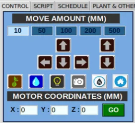
3)Lab Control: On the tab Control menu, there is a manual move control.
Fig 9 is the manual view of the move control in the Control menu. Move control can be used manually to control the Farmbot to perform a user command such as selecting how many migrations have been available i.e. 10, 100, 1000, 10000, 100000 mm. Then, the stepper motor would move towards the sloped x, Y and Z By clicking the X (Up), X (down), Y (left), Y (right), Z (UP), and Z (down) buttons, using the Coordinates Motor. The user can input the location or coordinate then will move the stepper motor to reach the destination and perform Some functions of Farmbot such as taking pictures, doing watering (water pump), doing the planting (vacuum pump) and activating the light.
4)Tab Control: On the tab Control menu, there is scanning control.
Fig 10 Display Scanning Control
Fig 10 is a scanning control function for shooting the whole Farmbot area displayed on the display scanning result. There are several variables that are used for scanning the start point, interval, and scanning step. Fig 11 is a system of movement in this research.
Fig 11 Flow Movement Scanning System & watering scheduling
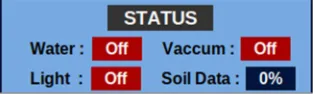
5)Status system: It displays Farmbot conditions in real time. Information contained in the status of the system, such as vacuum motor, pump motor, and lighting on or off display the value of soil sensor or moisture value of soil. Fig 12 is a display of system status.
Fig 12 Display Status System
6)Load & Run Script: it is executed to save or send commands to the Arduino in the form G-code Arduino. The commands given can either alter parameters such as the acceleration value, number of steps/mm for the x, Y, Z axis and take a picture or create a retrieval schedule or watering. The Select button is used to select a directory to store or select script files. The load button is used to select the files that are already available in the directory in the text form and display them in the notes script. The Save button is used to store note scripts in directories in text form. The Run button is used to send commands from the script note to the Arduino, each line of text in the note script will be sent to the Arduino using the Pyserial library. Script notes are used for writing, editing, storing the G-code text provided on the Login Notes script box. Fig 13 is a display loading & running script.
Fig 13 Display Load & Run Script
7)Event schedule: it is a menu for scheduling watering and scanning by selecting the time to do the watering or scanning and the desired loop interval. Watering scheduling is done to make it easier for users to periodically deliver water to plants by determining when to do the watering loop compared to doing so manually. The watering system is done for each grid and is done on the center of the grid on the planting area. This menu also allows you to choose the moisture to perform watering and the amount of water that is removed for watering. Fig 11 is a system of movement from scheduling watering to this research and Fig 14 is the display of event schedule.
8)Input & Database Planting: it is a menu where users can do plant planting by inputting data such as plant name, planting location and crop records then the data will be stored on the database planting and users can also Edit, update, delete and view existing plant data in the database. Fig 15 is an input display & database planting.
Fig 15 Display Input & Database Planting
9)Plant detection: A menu serves to detect weeds using image processing to detect all plants in the Farmbot area and mark each crop detected if the plant that is not on the list is considered as Weeds. Users can take pictures using the webcam, the image keeper of the Raspberry directory and select the image to be processed. To use this function the user must move the location or the coordinate of the Farmbot on the area you want to detect then photograph the area using the Save Image button and then press the Detect Plant button to select the image and process the image with the image Processing. The result of an image processing will appear a red circle represents the size of the plant from the plant center and the white line surrounds the outer edge of the plant. The smaller circles of the plant are weed. Fig 16 is a display of plant detection; Fig 17 is the result of the process of image processing from Plant Detection button.
Fig 16 Display Plant Detection
Fig 17 Display Image Processing Result
Fig 18 is a process of plant detection algorithm. Fig19 (a) is an example of a crop image used. Blur the image that works to blur the image, simplify, and reduce noise. The blur technique used is median blur on open CV using the function Cv2. median Blur () takes the median of all pixels under the
kernel area and the central element is replaced with this median value. Fig 19 (b) is the result of blurring of crop, weed and soil images in previous process.
Fig 18 Plant Detection Algorithm Process
The image that has done Blur is further converted into HSV image to get the plant color from the background of the image used to create a mask of the crop area and the background area of the image. Fig 20 (a) is the result of changing the RGB image to HSV. Create a mask using the RGB color limit of the converted image to HSV. Mask serves to select the green area of the image based on the green border input. Lower limit of green color in RGB color. Having a list of borders can then use the CV2. inRange function to perform the image threshold. The CV2. inRange function expects that the first three arguments are the image to be done in green color detection, the second is the lower limit of the color you want to detect, and the third argument is the upper limit of the color you want to detect. After calling Cv2. inRange, the binary mask is returned where the white pixel (255) represents the pixels that belong to the upper and lower limit ranges if they are not included in that range including the black pixels (0). Fig 20 (b) is the result of making masks in the thresholding process.
transformation. Creating a morphed image output that displays the original image of the plant from the results of the morphological Transformation process in the previous process, Fig 22 (a) is the result of returning the original image of the plant to the morphological transformation process.
Find and draw contours from the outer edges on the crop image and mark each plant center with a circle according to the size of the plant. Fig 22 (b) is the result of finding and practices contours in crop images, Fig 23 (a) is the return of the original image of the crop in the process of making contours and Fig 23 (b) is the result of the process of marking plants with circles.
(a) (b) Fig 19 (a) Original Image (b) Blurring Process Results
(a) (b)
Fig 20 (a) Convert RGB images to HSV (b) Thresholding Process Results
(a) (b)
Fig 21 (a) Result of Image return on Thresholding process (b) Results of the Morphological Transformation process
(a) (b)
Fig 22 (a) Result return image in the Morphological Transformation process (b) Results of making Contours
(a) (b)
Fig 23 (a) Results return image on the making of Countours (b) Crop Marking Process Results
Fig 24 is the overall working of the system is being discussed of hardware implementation.
Fig 24 Overview Farmbot Hardware
IV.CONCLUSIONS
Users can perform farming activities such as planting and watering using these Farmbot applications that are all controlled from the computer, and mobile phones from any location connected to the Internet. From the testing functionality to the features of the Farmbot system and the user system of the created Farmbot application, it can be concluded that all features work according to their functions. From the integration testing of the features in the application are monitoring, controlling and scheduling. From data monitoring tests conducted on two devices, namely the camera and the soil sensor can display images and display the value of soil humidity in real-time when connected to the Internet network. Monitoring tests can display the display of the spellcity of the planting area using auto-scanning. From testing controlling on hardware such as stepper motors, vacuum pumps, and water pumps that are used can run and work according to their functions. From testing scheduling to scheduling watering and scanning can run according to the time specified by the user. At scheduling watering pay attention to the soil, moisture parameters and the amount of water desired.
REFERENCES
[1] B. Krisnamurthi, “Analisa Ekonomi: Hari Pangan Sedunia dan Sawit Indonesia,” 2016. [Online]..[Accessed: 12-Apr-2019]
[2] United Nations, Department of Economic and Social Affairs, Population Division, 2009. World Population To Exceed 9 Billion By 2050.
[3] Badan Pusat Statistik (BPS), 2013. Laporan Hasil Sensus Pertanian 2013. Yogyakarta: Badan Pusat Statistik Provinsi DIY.
[4] Winarto, Y. & Yuniartha, L., 2018. Alih fungsi lahan sawah capai 200.000 ha per tahun. [Online].. [Accessed: 15-Apr-2019]
[5] Lu Y. Industry 4.0: A survey on technologies, applications and open research issues. Journal of Industrial Information Integration. 2017;6:1-10.
[6] Zhang N, Wang M, Wang N. Precision agriculture—a worldwide overview. Computers and Electronics in Agriculture. 2002;36(2):113-32.
[7] Bongiovanni, R. & Lowenberg-Deboer, J., 2004. Precision Agriculture, 5(4), pp. 359-387.
[9] Sommerville, Ian.2011.Software Engineering. 9th Edition. America : Pearson Education ,Inc.
[10] R. Aronson, "Exploring the Carbon Footprint of FarmBot," [Online]. Available: Farmbot.io/footprint/.
[11] E. A. Jack Brown, "Polar Coordinate FarmBot Final Project Report," 2017.