Iranian Journal of Chemical Engineering Vol. 6, No. 4 (Autumn), 2009, IAChE
Numerical Study of Non-Newtonian Flow Through
Rectangular Microchannels
M. R. Mahjoob1, S. Gh. Etemad1, J. Thibault2
1- Department of Chemical Engineering, Isfahan University of Technology, Isfahan 84156-83111, Iran. 2- Department of Chemical and Biological Engineering, University of Ottawa, Ottawa,
Ontario K1N 6N5, Canada.
Abstract
A numerical investigation was carried out to solve the flow dimensionless partial differential equations through rectangular microchannels. A purely viscous power law model was used to characterize the flow behavior of non-Newtonian fluids. The flow was assumed to be steady and laminar, and slip conditions were used as boundary conditions at the walls. The problem was solved for different power law indices as well as for various rectangular aspect ratios. Results showed that the effects of slip velocity on dilatant fluids are more pronounced than that for pseudoplastic fluids. An increase in the power law index enhances the product of the friction factor and the Reynolds number, as well as the dimensionless incremental pressure drop and the dimensionless maximum velocity, while the hydrodynamic entrance length decreases. Results emphasize the significant effects of channel aspect ratio on the hydrodynamic flow behavior through microchannels.
Keywords: Non-Newtonian, Microchannel, Rectangular, Slip velocity, Power law
Corresponding author: [email protected]
1- Introduction
Today, the study of flow behavior of fluids in microchannels is the subject of many investigations because of the importance of the flow and heat transfer at the microscale level. This vivid interest in microscale transport phenomena is motivated by their usefulness for the design, fabrication and operation of various microdevices or systems such as microchannel heat sinks, micropumps, microreactors, microvalves and
microactuators.
Iranian Journal of Chemical Engineering, Vol. 6, No. 4 45 microdevice fabrication, bioengineering, and
micro-electromechanical systems (MEMS). Most of the microsystems use microchannels with noncircular cross-sections. The typical hydraulic diameters of such microchannels are in order of 1 to 100µm.
The physics describing the fluid flow and heat transfer in microdevices changes substantially compared to fluid flow and heat transfer at a larger scale. Slip flow for fluids and temperature jump at the walls for gases are examples of typical differences in the physics of fluid flow and heat transfer at the the microscale level. The occurrence of slip near the wall has created a challenging problem for fluid mechanics. Slip of fluid in polymeric melts and solutions has been considered in several investigations [Wang [1]; Leger et al. [2]]. For the slip flow regime, the standard Navier-Stokes and energy equations can still be used provided that modifications to the boundary conditions are made to allow for the velocity slip and the temperature jump at the walls.
The Knudsen number (Kn) is defined as the ratio of the mean free path ë to the characteristic length of the system. For small values of the Knudsen number (Kn ≤ 10-3), the fluid is considered to be a continuum, while for large values (Kn ≥ 10) the fluid is considered to be a free molecular flow. For Knudsen numbers in the range of 10−3
≤Kn≤10−1, deviations from continuum behavior arise near the walls where in a thin layer called the Knudsen layer, molecular collisions with the walls become more important than intermolecular collisions. This range of Knudsen numbers corresponds to the slip flow regime. A Knudsen number
equal to zero corresponds to the no-slip flow boundary condition, whereas for a Knudsen number greater than zero, slip flow occurs at the wall. Higher Knudsen numbers lead to higher flow velocity and temperature jump at the boundaries.
For gases, the slip velocity was defined as a function of the fluid molecular properties, and surface and wall shear stresses [Erich [3]; Maxwell[4]]. Many mechanisms have been proposed to explain the slip velocity in polymeric melts and solutions. However, mechanisms that have received wider acceptance in recent years are polymer chain disentanglement [Brochard and de Gennes [5]] and debonding [Hill [6]] at the wall-polymer interface.
Experiments were performed by Kandliker et al. [7] to study the effect of the relative roughness on the pressure drop and heat transfer in two capillary tubes with diameters of 1076 µm and 600 µm and with a relative roughness ranging from 0.00178 to 0.003. Shen et al. [8] investigated experimentally the single phase convective heat transfer in a compact heat sink consisting of several rectangular microchannels of 300 µm wide and 800 µm deep.
continuum approach in combination with slip boundary conditions to model the flow and heat transfer problems in microchannel flows with relatively low rarefaction effects. Compressibility effects on the friction factor and the application of higher order slip conditions were also investigated.
Renksizbulut et al. [27] investigated the rarefied gas flow and heat transfer in the entrance region of rectangular microchannels in the slip-flow regime. A control-volume based numerical method was used to solve the Navier-Stokes and energy equations with velocity-slip and temperature-jump condi-tions at the walls. The effects of the Reynolds number, the channel aspect ratio, and the Knudsen number on the simult-aneously developing velocity and temperature fields were studied.
Giudice et al. [28] studied the effects of viscous dissipation and temperature dependent viscosity in both thermally and simultaneously developing laminar flows of liquids in straight microchannels of arbitrary, but constant, cross-sections. Barkhordari and Etemad [29] investigated the forced convection heat transfer of power law model for non-Newtonian fluids through circular microchannels for laminar flow conditions. They studied the effects of velocity slip and
slip coefficient â which was defined as the ratio of velocity of fluid at the wall to the mean velocity of the fluid.
In the present investigation, the isothermal laminar flow of power law fluids in the entrance region of rectangular microchannels with aspect ratios ranging from 1 to 5 was investigated. A control-volume finite dif-ference method was used to solve the appropriate dimensionless momentum equa-tions with velocity-slip at the walls. The effects of the Reynolds number and the channel aspect ratio on the hydrodynamically developing condition, and on the key flow parameters such as the entrance length, the product of the friction factor and the Reynolds number (f.Re) and the fully developed incremental pressure drop number (K(∞)) were examined in details.
2- Problem Statement
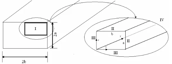
The problem under consideration is a hydrodynamically developing as well as developed section of a rectangular microchannel. The geometry specifications and the considered flow domain are presented by Fig. 1. Due to the symmetry condition prevailing in this system, only one quarter of the microchannel was considered as the computational domain.
Iranian Journal of Chemical Engineering, Vol. 6, No. 4 47 The following assumptions were made to
model the hydrodynamic behavior through the rectangular microchannel:
Steady State
Constant fluid properties Laminar flow
Non-Newtonian fluid (power law
model)
The aspect ratio of the rectangular channel () and its hydraulic diameter (Dh) are defined as: a b (1) b a ab Dh
2 (2)
The Ostwald-de Waele or power law model with the following form has been used to correlate the shear stress to shear rate:
n 1 / 2 1
k :
2
(3)
Where
is the shear stress tensor, is therate of deformation in Cartesian coordinates, n is the power law index, and k is the
consistency index.
The dimensionless hydrodynamic governing equation in Cartesian coordinates can be written as [Etemad et al. [30]]:
Continuity:
U V W
0
X Y Z
(4)
X-Momentum:
U U U P
U W
X Y Z X
1 C D E
Re X Y Z
(5) Y-Momentum:
V V V P
U V W
X Y Z Y
1 F D G
Re Y X Z
(6) Z-Momentum:
W W W P
U V W
X Y Z Z
1 H G E
Re Z Y X
(7) Where: X U C n
1)/2 ( 2 2 (8) X V Y U D
n1)/2 ( 2 (9) X W Z U E
n1)/2 ( 2 (10) Y V F n
1)/2 (
2
( n 1) / 2
V W
G
2 Z Y
(12) Z W H n
1)/2 (
2
2 (13)
2 2 2
2 2 2
U V W
2
2 X Y Z
U V W V U W
Y X Y Z Z X
(14)
The dimensionless parameters are defined as follows: h x X D , h D y Y ,
h D
z
Z (15)
x
e v U
v
, y
e v V
v
, z
e v W v (16) 2 e p p P v (17) + h y Y =
D .Re (18)
o n h n 2 e k D v Re (19)
In the analysis of the governing equations, the friction factor and the incremental pressure drop are used and are defined as follows: 2 u f 2 e w (20) ) ( ) 4 Re)( . ( 2
2 f Y K y
u p P e (21)
In the fully developed region, K(y) is designated as K().
) ( K ) Y 4 Re)( . f (
P
(22)
The following equations show the dimensionless hydrodynamic variables for different boundary conditions:
Boundary condition at the inlet (Boundary I, Y = 0):
U 0 , V 1 , W 0 (23)
Boundary condition at the wall (Boundary II, Z = a, X = b):
U 0 , V , W0 (24)
Boundary condition at on the symmetry planes (Boundary III, Z = 0, X = 0):
U V W U V W
0
X X X Z Z Z
(25)
The fluid at the outlet is assumed to be fully developed.
Hydrodynamic Boundary condition at the outlet (Boundary IV, Y = Y):
V
0 , U W 0 Y
Iranian Journal of Chemical Engineering, Vol. 6, No. 4 49
3- Result and Discussion
In this investigation the laminar flow of the power law fluid in the entrance region of rectangular microchannels with aspect ratios ranging from 1 to 5 were investigated. A control-volume finite difference method was used to solve the dimensionless equations of motion with appropriate boundary conditions and velocity-slip at the walls. The number of meshes (30×300×30 grids) was selected in such a way to achieve a solution that was independent of the mesh size. A finer mesh distribution was used in the entrance region and in the vicinity of the wall to accommodate the higher velocity gradient in these regions. The accuracy of the numerical procedure was validated by comparing the results for some specific cases with available analytical and numerical solutions.
The maximum fully developed velocity for laminar flow of Newtonian fluid in a rectangular duct (no-slip condition) was obtained by [Shah and Bhatti [31]]:
max
m
v M 1 N 1
v M N
+ +
⎛ ⎞⎛ ⎞
=⎜⎝ ⎟⎜⎠⎝ ⎟⎠ (27)
The value of M and N are given in Table 1 and also are expressed by the following relations:
( )
* 1.4M 1.7 0.5= + α − (28)
*
* *
1
2 for
3 N
1 1
2 0.3 for
3 3
⎧ α ≤
⎪⎪
= ⎨ ⎛ ⎞
⎪ + ⎜α − ⎟ α >
⎪ ⎝ ⎠
⎩
(29)
Where α* is equal to 1 α .
The product of the fully developed Fanning friction factor and the Reynolds number for the laminar flow of Newtonian fluids in rectangular channels is given by the following equation [Shah and Bhatti [31]]:
* *2 * 3
* 4 * 5
f.Re 24(1 1.3553 1.9467 1.7012 0.9564 0.2537 )
= − α + α − α
+ α − α
(30)
Table 1. Value of M and N for Eq.(27)
0.2 0.25
1 3 0.5
α*
6.60 5.19
3.78 2.37
M
2 2
2 2
N
The fully developed Fanning friction factor for laminar flow of power law fluids in a square duct was obtained by Rohsenow and Hartnett [32]:
n
1.7330
f .Re 1.874 5.8906 n
⎛ ⎞
= ⎜ + ⎟
⎝ ⎠ (31)
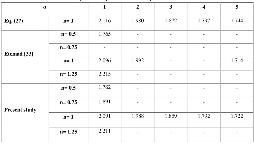
The results obtained in this investigation were compared with the equation of Shah and Bhatti [31], Rohsenow and Hartnett [32], and Etemad [33]. Results of this comparison are presented in Tables 2-4 and an excellent agreement was obtained, thereby validating the accuracy of the simulations performed in this study.
a decrease in the power law index which is due to the mass conservation requirement. The centerline velocity and the maximum axial velocity increase with an increase in the axial distance which is directly related to flow development. The data for fully developed maximum axial velocity are tabulated in Table 5. When the power law index decreases, the axial velocity of the fluid near the wall increases and the mass conservation constraint forces the fluid to
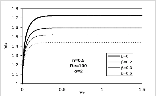
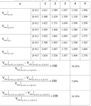
correspondingly slow down in the center of the microchannel. Based on the results of Table 5 for a square duct, an increase in the slip velocity at the walls decreases the maximum dimensionless velocity and this difference becomes more pronounced for higher geometry aspect ratios. The effects of the slip velocity for various power law indices are different and the variation of Vmax is larger for higher values of n.
Table 2. Comparison of the developed Vmax (no-slip condition)for different aspect ratios and non-Newtonian fluids obtained from the present study and available analytical and numerical solutions
5 4
3 2
1 á
1.744 1.797
1.872 1.980
2.116 n= 1
Eq. (27)
- -
- -
1.765 n= 0.5
- -
- -
- n= 0.75
1.714
1.992
2.096 n= 1
- -
- -
2.215 n= 1.25
Etemad [33]
- -
- -
1.762 n= 0.5
- -
- -
1.891 n= 0.75
1.722 1.792
1.869 1.988
2.091 n= 1
- -
- -
2.211 n= 1.25
Present study
Table 3. Comparison of the developed f.Re for a square duct obtained from the present study with available analytical and numerical solutions.
1.25 1
0.75 0.5
n
22.283 14.230
9.057 5.723
Eq. (31)
22.710 14.234
6.219
Etemad [33]
22.724 14.228
8.988 6.225
Iranian Journal of Chemical Engineering, Vol. 6, No. 4 51 Table 4. Comparison of the developed f.Re for Newtonian fluids obtained from the present study with available
analytical and numerical solutions for different aspect ratios.
5 4
3 2
1 á
19.071 18.234
17.095 15.557
14.223 Eq. (30)
19.073
15.559
14.234 Etemad [33]
19.075 18.239
17.098 15.557
14.228 Present study
Re=100 á=2
â=0.2
1 1.1 1.2 1.3 1.4 1.5 1.6 1.7 1.8 1.9
0 0.5 1 1.5
Y+
V
c
n=0.5 n=0.75 n=1 n=1.25
Figure 2. The effect of power law index on the centerline velocity
n=0.5 Re=100
á=2
1 1.1 1.2 1.3 1.4 1.5 1.6 1.7 1.8
0 0.5 1 1.5
Y+
V
c
â=0 â=0.2 â=0.3 â=0.5
Re=100 n=0.5
â=0
1 1.1 1.2 1.3 1.4 1.5 1.6 1.7 1.8
0 0.5 1 1.5
Y+
V
c
á=2 á=3 á=4 á=5
Figure 4. The effect of aspect ratio on the centerline velocity
Table 5. Results of developed Vmax for â = 0.2 and â = 0.5
5 4
3 2
1 á
1.496 1.518
1.547 1.589
1.611
â=0.2
1.309 1.330
1.359 1.439
1.488
â=0.5 max n 0.5
V
1.550 1.599
1.658 1.731
1.822
â=0.2
1.354 1.386
1.424 1.466
1.565
â=0.5 max n 0.75
V
1.575 1.627
1.695 1.801
1.952
â=0.2
1.363 1.398
1.441 1.503
1.708
â=0.5 max n 1
V
1.604 1.650
1.725 1.847
2.047
â=0.2
1.376 1.404
1.457 1.526
1.824
â=0.5 max n 1.25
V
10.42%
max n 0.5 , 2, 0.2 max n 0.5 , 2, 0.5
max n 0.5 , 2, 0.5
V V
100 V
7.69%
max n 0.5 , 1, 0.2 max n 0.5 , 5, 0.2
max n 0.5 , 5, 0.2
V V
100 V
16.24%
max n 1.25 , 2, 0.2 max n 0.5 , 2, 0.2
max n 0.5 , 2, 0.2
V V
100 V
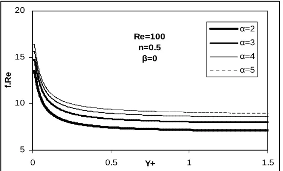
Iranian Journal of Chemical Engineering, Vol. 6, No. 4 53 The product of the friction factor and the
Reynolds number are presented in Figs. 5-7 for different values of the power law indices, slip coefficients and aspect ratios. The results presented in these figures show that the friction factor decreases with an increase of the axial distance. The higher initial values of the friction factor are related to the high pressure drop in the developing section of the channel. The data for the fully developed friction factor are tabulated in Table 6. When the power law index increases, for the same slip coefficient and aspect ratio, the velocity gradient of the fluid close to the wall
increases and the wall shear stress, and consequently the friction factor, increases. For a given power law index and channel aspect ratio, an increase in the slip coefficient leads to a decrease in the product of the friction factor and the Reynolds number. This decrease in fRe is caused by lower wall
velocity gradients due to higher slip coefficients. The results of Fig. 7 and Table 6 emphasize the importance of the aspect ratio. Indeed, narrowing the cross section by increasing the aspect ratio enhances f.Re because of the resulting higher velocity gradient close to the walls.
Re=100
á=2
â=0.2
0 10 20 30 40
0 0.5 1 1.5
Y+
f.
R
e
n=0.5 n=0.75 n=1 n=1.25
Figure 2. The effect of the power law index on the product of the friction factor and the Reynolds number
n=0.5 Re=100
á=2
4 6 8 10 12 14 16
0 0.5 Y+ 1 1.5
f.
R
e
â=0 â=0.2 â=0.3 â=0.5
Re=100 n=0.5
â=0
5 10 15 20
0 0.5 Y+ 1 1.5
f.
R
e
á=2 á=3 á=4 á=5
Figure 4. The effect of the aspect ratio on the product of the friction factor and the Reynolds number
Table 6. Results of developed f.Re for â = 0.2 and â = 0.5
5 4
3 2
1 á
7.908 7.524
7.207 6.382
5.688
â=0.2
6.205 5.912
5.493 5.481
4.922
â=0.5 n 0.5
f .Re
11.157 10.653
10.206 8.934
7.017
â=0.2
7.852 7.500
7.030 6.722
5.278
â=0.5 n 0.75
f .Re
15.354 14.547
13.760 12.539
11.313
â=0.2
9.614 9.187
8.592 7.834
7.173
â=0.5 n 1
f .Re
21.373 20.525
18.968 17.529
16.465
â=0.2
11.840 11.366
10.532 9.711
8.671
â=0.5 n 1.25
f .Re
16.44%
n 0.5 , 2, 0.2 n 0.5 , 2, 0.5
n 0.5 , 2, 0.5
f .Re f .Re
100 f .Re
39.03%
n 0.5 , 5, 0.2 n 0.5 , 1, 0.2
n 0.5 , 1, 0.2
f .Re f .Re
100 f .Re
174.66%
n 1.25 , 2, 0.2 n 0.5 , 2, 0.2
n 0.5 , 2, 0.2
f .Re f .Re
100 f .Re
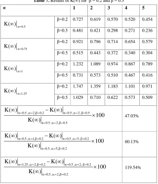
Iranian Journal of Chemical Engineering, Vol. 6, No. 4 55 Table 7. Results of K(∞) for â = 0.2 and â = 0.5
5 4
3 2
1 á
0.454 0.520
0.570 0.619
0.727
â=0.2
0.236 0.271
0.298 0.421
0.481
â=0.5 n 0.5
K( )
0.579 0.654
0.714 0.796
0.921
â=0.2
0.304 0.340
0.372 0.443
0.515
â=0.5 n 0.75
K( )
0.789 0.867
0.974 1.089
1.232
â=0.2
0.416 0.467
0.510 0.573
0.731
â=0.5 n 1
K( )
0.971 1.101
1.183 1.359
1.747
â=0.2
0.509 0.573
0.622 0.710
1.029
â=0.5 n 1.25
K( )
47.03%
n 0.5 , 2, 0.2 n 0.5 , 2, 0.5
n 0.5 , 2, 0.5
K( ) K( )
100 K( )
60.13%
n 0.5 , 1, 0.2 n 0.5 , 5, 0.2
n 0.5 , 5, 0.2
K( ) K( )
100 K( )
119.54%
n 1.25 , 2, 0.2 n 0.5 , 2, 0.2
n 0.5 , 2, 0.2
K( ) K( )
100 K( )
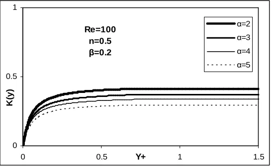
Incremental pressure drops are presented in Figs. 8-10 for different values of the power law indices, slip coefficients and aspect ratios. Results of these figures show that K(y) increases with an increase in the axial distance. This increase is the result of the higher difference between the dimensionless pressure drop in the developing section and in the developed part of the channel. In addition, results show that a decrease in the power law index increases the hydrodynamic entrance length which is due to a flatter velocity profile for pseudoplastic fluids. There are two important factors affecting the
Re=100
á=2
â=0.2
0 0.5 1 1.5 2 2.5
0 0.5 Y+ 1 1.5
K
(y
)
n=0.5 n=0.75 n=1 n=1.25
Figure 5. The effect of the power law index on the incremental pressure drop
Re=100 n=0.5
á=2
0 0.5 1
0 0.5 Y+ 1 1.5
K
(y
)
â=0 â=0.2 â=0.5
Figure 6. The effect of the slip coefficient on the incremental pressure drop
Re=100 n=0.5
â=0.2
0 0.5 1
0 0.5 Y+ 1 1.5
K
(y
)
á=2 á=3 á=4 á=5
Iranian Journal of Chemical Engineering, Vol. 6, No. 4 57
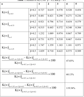
Table 7. Results of K(∞) for β = 0.2 and β = 0.5
5 4
3 2
1
α
0.454 0.520
0.570 0.619
0.727
β=0.2
0.236 0.271
0.298 0.421
0.481
β=0.5
n 0.5
K( )∞ =
0.579 0.654
0.714 0.796
0.921
β=0.2
0.304 0.340
0.372 0.443
0.515
β=0.5
n 0.75
K( )∞ =
0.789 0.867
0.974 1.089
1.232
β=0.2
0.416 0.467
0.510 0.573
0.731
β=0.5
n 1
K( )∞ =
0.971 1.101
1.183 1.359
1.747
β=0.2
0.509 0.573
0.622 0.710
1.029
β=0.5
n 1.25
K( )∞ =
47.03%
n 0.5 , 2, 0.2 n 0.5 , 2, 0.5
n 0.5 , 2, 0.5
K( ) K( )
100 K( )
= α= β= = α= β=
= α= β=
∞ − ∞
× ∞
60.13%
n 0.5 , 1, 0.2 n 0.5 , 5, 0.2
n 0.5 , 5, 0.2
K( ) K( )
100 K( )
= α= β= = α= β=
= α= β=
∞ − ∞
× ∞
119.54%
n 1.25 , 2, 0.2 n 0.5 , 2, 0.2
n 0.5 , 2, 0.2
K( ) K( )
100 K( )
= α= β= = α= β=
= α= β=
∞ − ∞
× ∞
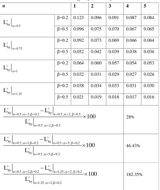
Conclusion
In the present paper, a numerical study is carried out to investigate the flow field of non-Newtonian fluids through rectangular microchannels. The problem was solved for different aspect ratios and various slip velocities at the walls. Generally for microchannels, the effect of the aspect ratio and the slip velocity for pseudoplastic fluids is less significant than for dilatant fluids which are due to the flatter velocity profile for lower power law indices. Results show that the product f.Re, the maximum centreline velocity and K(∞) increase, and L+hy decreases with an increase in the power
Table 8. Results of L+hy for â = 0.2 and â = 0.5
5 4
3 2
1 á
0.084 0.087
0.091 0.096
0.123
â=0.2
0.065 0.067
0.070 0.075
0.096
â=0.5 hy n 0.5
L
0.064 0.066
0.069 0.073
0.092
â=0.2
0.036 0.038
0.039 0.042
0.052
â=0.5 hy n 0.75
L
0.053 0.054
0.057 0.060
0.064
â=0.2
0.026 0.027
0.029 0.031
0.032
â=0.5 hy n 1
L
0.030 0.031
0.033 0.034
0.038
â=0.2
0.016 0.017
0.018 0.019
0.021
â=0.5 hy n 1.25
L
28%
hyn 0.5 , 2, 0.2 hyn 0.5 , 2, 0.5
hy n 0.5 , 2, 0.5
L L
100 L
46.43%
hyn 0.5 , 1, 0.2 hyn 0.5 , 5, 0.2
hy n 0.5 , 5, 0.2
L L
100 L
182.35%
hyn 0.5 , 2, 0.2 hyn 1.25 , 2, 0.2
hy n 1.25 , 2, 0.2
L L
100 L
Nomenclature
a Half height of the rectangular microchannnel (Fig. (1)), m
b Half width of the rectangular microchannnel (Fig. (1)), m
C Defined by Eq.(8), dimensionless D Defined by Eq.(9), dimensionless Dh Hydraulic diameter, m
E Defined by Eq.(10), dimensionless F Defined by Eq.(11), dimensionless
f Friction factor w 2 e 1 2 v
G Defined by Eq.(12), dimensionless H Defined by Eq.(13), dimensionless K(∞) Fully developed incremental
pres-sure drop number, dimensionless K(y) Incremental pressure drop number,
dimensionless k
Consistency index at reference temperature. N sn/m2
Kn Knudsen number, dimensionless L+hy Hydraulic developing length,
di-mensionless
Iranian Journal of Chemical Engineering, Vol. 6, No. 4 59 n Power law index, dimensionless
N Defined by Eq.(29), dimensionless p Pressure, Pa
p Pressure at the inlet, Pa
P Dimensionless pressure 2 e p p
v
Re Reynolds number
2 n n e h v D
k
v Axial velocity, m/s
U Dimensionless velocity in the x direction x
e v v
, dimensionless
V Dimensionless velocity in the y direction y
e v v
, dimensionless
W Dimensionless velocity in the z direction z
e v v
, dimensionless
x Transverse horizontal distance, m X Dimensionless transverse horizontal
distance h x D
, dimensionless
y Axial distance, m
Y Dimensionless axial distance
h y D
, dimensionless
Y+ Dimensionless hydrodynamic axial distance
h y D .Re
z Transverse vertical distance, m Z Dimensionless transverse vertical
distance h z D
, dimensionless
Greek symbols
á Aspect ratio, dimensionless
á* Reversed of á
â Slip coefficient s
m v v
,
dimensionless
ô Shear stress, N/m2
Ä Deformation tensor in cylindrical
coordinate, s-1
2
Defined by Eq.(14), dimensionless
ë mean free path, m
Subscripts
c Centerline value
e Evaluated at entrance condition m Mean value
max Maximum value s Slip value
w Calculated at wall condition x x direction
y y direction z z direction
References
[1] Wang, S. Q., “Molecular transition and dynamics at polymer/wall interfaces: Origins of Flow Instabilities and Wall Slip”, Adv. Polym. Sci, vol. 381, pp. 225-238, (1999).
[2] Leger, L., Raphael, E. and Hervet, H.,
“Surface-Anchored Polymer Chains: Their role in adhesion and friction”, Adv. Polym. Sci, vol. 138, pp. 185-225, (1999).
[3] Erich, F. R., Rheology: Theory and Application, Academic Press Inc., New York, (1978).
[5] Brochard F. and De Gennes, P. G., “Shear dependent slippage at a polymer/solid interface”, Langmuir, vol. 8, pp. 3033-3037, (1992).
[6] Hill, D. A., “Wall Slip in Polymer Melts: a Pseudo-Chemical Model”, J. Rheol., vol. 42, pp. 581-601, (1998).
[7] Kandlikar, S. G., Joshi, S. and Tian, S.,
“Effect of channel roughness on heat transfer and fluid flow characteristics at low reynolds numbers in small diameter tubes”, Proc of 35th National Heat Transfer Conference, Anaheim CA, USA, (2001). [8] Shen, S., Xu, J.L., Zhou, J. J. And Chen,
Y., “Flow and heat transfer in microchannels with rough wall surface”, energy conversion and management vol. 47, pp. 1311–1325, (2006).
[9] Wu, P. and Little, W. A., “Measurements of friction factors for the flow of gases in very fine channels used for micro miniature Joule–Thomson refrigerators”, Cryogenics, vol. 23, pp. 273–277, (1983).
[10] Pfahler, J., Harley, J., Bau, H., and Zemel, J. N., “Gas and liquid flow in small channels, Proceedings of ASME Winter Annual Meeting, Micro Mechanical Sensors, Actuators, and Systems”, DSC-32, ASME,, New York, pp. 49–60,New York, (1991).
[11] Beskok, A. And Karniadakis, G. E.,
“Simulation of slip-flows in complex microgeometries”, J. Micromech. Syst. DSC, vol. 40, pp. 355–370, (1992).
[12] Beskok, A. And Karniadakis, G. E.,
“Simulation of heat and momentum transfer in complex micro geometries”, J. Therm. Heat Transfer, vol. 8, pp. 647-653, (1994).
[13] Arkilic, E. B., Breure, K. S., And Schmidt, M. A., “Gaseous flow in microchannels,
application of micro-fabrication to fluid mechanics”, ASME FED 197, pp. 57-66, (1994).
[14] Arkilic, E. B., Schmidt, M. A. and Breuer, K. S., “Gaseous slip flow in long microchannels”, J. Microelec-tromech. Syst., vol. 6, pp. 167–178, (1997).
[15] Harley, J. C., Huand, Y., Bau, H. and Zemel, J. N., “Gas Flow in Micro-channels”, J. Fluid Mech, vol. 284, pp. 257–274, (1995).
[16] Morinim, G. L. and Spiga, M., “Slip flow in rectangular microtubes”, Microscale Thermophys. Engrg. , vol. 2, pp. 273–282, (1998).
[17] Beskok, A., “A model for flows in channels, pipes, and ducts at micro and nano-scales”, Microscale Thermophys. Engrg., vol. 3, pp. 43-77, (1999).
[18] Meinhart, C. D., Wereley, S. T. and Santiago, J. G., “PIV Measurements of a Microchannel Flow”, Experiments in Fluids, vol. 27, pp. 414–419, (1999). [19] Jang, J. and Wereley, S. T., “Pressure
Distribution of Gaseous Slip Flow in Straight and Uniform Rectangular Microchannels”, Microfluid Nanofluid, vol. 1, pp. 41–51, (2004).
[20] Xue, H. and Fan, Q., “A New Analytic Solution of the Navier–Stokes Equations for Microchannel Flows”, Microscale Thermophys. Engrg., vol. 4, pp. 125– 143, (2000).
[21] Araki, T., Kim, M. S., Iwai, H. and Suzuki, K., “An Experimental Inves-tigation of Gaseous Flow Charac-teristics in Microchannels”, Microscale Thermophys. Engrg., vol. 6, pp. 117–130, (2002).
Iranian Journal of Chemical Engineering, Vol. 6, No. 4 61 Transfer, vol. 47, pp. 3877–3887, (2004).
[23] Turner, S. E., Lam, L. C., Faghri, M. And Gregory, O. J., “Experimental Investigation of Gas Flow in Microchannels”, J. Heat Transfer, vol. 126, pp. 753–763, (2004). [24] Colin, S., “Rarefaction and Compressibility
Effects on Steady or Transient Gas Flows in Microchannels”, Second International Conference on Micro-channels and Minichannels, Rochester, New York, USA, pp. 13–24, (2004).
[25] Morini, G. L., Spiga, M. and Tartarini, P.,
“The rarefaction effects on the friction factor of gas flow in microchannels”, Superlattices Micro-struct, Vol. 35, pp. 587–599, (2004).
[26] Shih, J. C., Ho, C., Liu, J. and Tai, Y.,
“Monatomic and polyatomic gas flow through uniform microchannels”, 1996 National Heat Transfer Conference, Micro Electro Mechanical System (MEMS), Atlanta, GA, DSC 59, pp. 197-203, (1996). [27] Renksizbulut, M., Niazmand, H. and Tercan, G., “Slip-flow and heat transfer in rectangular microchannels with constant wall temperature”, Int. J. Thermal Sciences, vol. 45, pp. 870–881, (2006). [28] Del Giudice, S., Nonino, C. and Savino, S.,
“Effects of viscous dissipation and temperature dependent viscosity in thermally and simultaneously developing laminar flows in microchannels”, Int. J. Heat and Fluid Flow, vol. 28, pp. 15–27, (2007).
[29] Barkhordari, M. and Etemad, S. Gh.,
“Numerical study of slip flow heat transfer of Non-Newtonian fluids in circular microchannels”, J. Heat and Fluid Flow, vol. 28, pp. 1027-1033, (2007).
[30] Etemad, S. Gh., Mujumdar, A. S. and Nassef, R., R., “Simultaneously developing flow and convection heat transfer in semi-circular and equilateral triangular duct”, Appl. Math. Modelling, vol. 20, pp. 898-908, (1996). [31] Shah, R. K. and Bhatti, M. S., Handbook of
Single-Phase Convective Heat Transfer, John Wiley and Sons, pp.3-45 ,3-51, New York, (1987).
[32] Rohsenow, W. M. and Hartnett, J. P., Handbook of Heat Transfer, Third Edition, Mc Graw-Hill, Chapter 10, pp.14-20, (1998).