Available Online at www.ijpret.com
147
INTERNATIONAL JOURNAL OF PURE AND
APPLIED RESEARCH IN ENGINEERING AND
TECHNOLOGY
A PATH FOR HORIZING YOUR INNOVATIVE WORK
EFFECT OF CIRCULAR TUNNEL ON EXESTING BUILDINGS UNDER SEISMIC
LOADING
DHATRAK A. I.1, DHENGLE S. D.2
1. Associate Professor, Department of Civil Engineering, Government College of Engineering,
Amravati, Maharashtra, India.
2. PG Student, Department of Civil Engineering, Government College of Engineering, Amravati,
Maharashtra, India.
Accepted Date: 27/02/2014 ; Published Date: 01/05/2014
\
Abstract: The paper deals with analysis of the time history response of the soil profile surrounding tunnel during earthquakes. The analysis presented illustrates the behavior of buildings due to tunneling under seismic loading condition. Generally tunnels have a fairly high safety against earthquakes. However , at the earth surface the reaction to the earthquake action may lead to more complicated consequences. The proposed approach can also be used for estimation of dynamic load influence on development of differential settlement for nearby structure. A real tunnel model which is subjected to earthquake forces was considered and for the purpose of analysis modified numerical program MIDAS 2D was used.
Keywords: Tunnel excavation, superstructure, Earthquake, MIDAS 2D
Corresponding Author: MR. DHENGLE S. D.
Access Online On:
www.ijpret.com
How to Cite This Article:
SD Dhengle, IJPRET, 2014; Volume 2 (9): 147-155
Available Online at www.ijpret.com
148 INTRODUCTION
One of the most important factors affecting the design of the structures is the impact of the seismic loadings on the design displacements. Where as, the influences of the near structures on the existing buildings, which sometimes can cause great changes in forces and displacements. Thus, the induced displacement in the adjacent buildings due to newly constructed underground tunnel will be investigated in this study. The behaviour of the super structures, such as buildings, bridges, under seismic conditions is highly affected by the underlying soil layer. So far, extensive studies have been carried out to know the impact of the earthquakes on underground and ground structures and it can be evaluated, whether the amount of variations in displacements are in the allowable ranges, and what measures are needed to save the structures in case of excessive displacement. Different shapes of tunnels are shown in figure1.
Figure 1: Circular, Horseshoe and Curvilinear (Oval) Tunnel (FHWA, 2005a)
Engineering Approach to Seismic Analysis and Design
Available Online at www.ijpret.com
149 inertial effects of the structure itself. This led to the development of design methods such as the Seismic Deformation Method that explicitly considers the seismic deformation of the ground. Many researchers present a review on the seismic behavior and design of underground structures in soft ground with an emphasis on the development of the Seismic Deformation Method. The behavior of a tunnel is sometimes approximated to that of an elastic beam subject to deformations imposed by the surrounding ground.
1. Numerical Programme
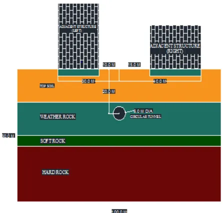
The numerical program reported herein, that involves a real tunnel model which is subjected to earthquake forces are considered. A tunnel of 6 m diameter and overburden depth 17 m was considered. Which was embedded in the formation comprises four alternating hard rock, soft rock weather rock and top clay layers. The left and right structures are placed at a distance of 10 m and 15 m from the center of tunnel and the length of structures are 20m and 25m respectively. A typical cross section shows the information about strata, the alignment of tunnel and other related details is shown in Fig. 2.
Figure 2: Ground Profile and The Positions of the Existing Structures and Tunnel in the Selected Model.
2.1 Material
Available Online at www.ijpret.com
150 Table 1: Material Properties of Ground Medium
Depth (m) DryUnit Weight (kN/m) Poisons Ratio (µ) Elastic Modulus
E (kN/m2)
Angle of
Friction Ø
Cohesion
C
(kN/m2)
15 18 0.3 40000 33 28
15 21 0.3 200000 37 40
5 24 0.27 1350000 37 100
25 26 0.2 8900000 55 500
Table 2: Material Properties of Structural Medium.
Sr. No Material Type Modulus of Elasticity
(kN/m2)
Poisons Ratio
(µ )
Unit Weight
(kN/m3)
1 Structure 20000000 0.2 25
2 Soft Shotcrete 5000000 0.3 24
3 Hard Shotcrete 15000000 0.3 24
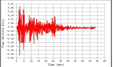
2.2 Dynamic Analysis
A set of input acceleration time history had been seleced from data base records. The finite element software MIDAS GTS 2D has been used to perform two dimensional dynamic analysis.
Available Online at www.ijpret.com
151 2. Numerical Results and Discussion
The numerical analysis presented hear was used to examine the effect of dynamic loads on the stability of nearby structures perticularly buildings, tunnels and especially due to earthquakes. Vertical and horizontal displacements were estimated to examine the behavior of structure under following cases, as mentioned in table.3
Table 3: Different Loading Cases.
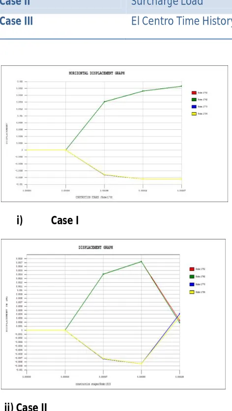
Case I Self Load of Structure
Case II Surcharge Load
Case III El Centro Time History Loading.
i) Case I
Available Online at www.ijpret.com
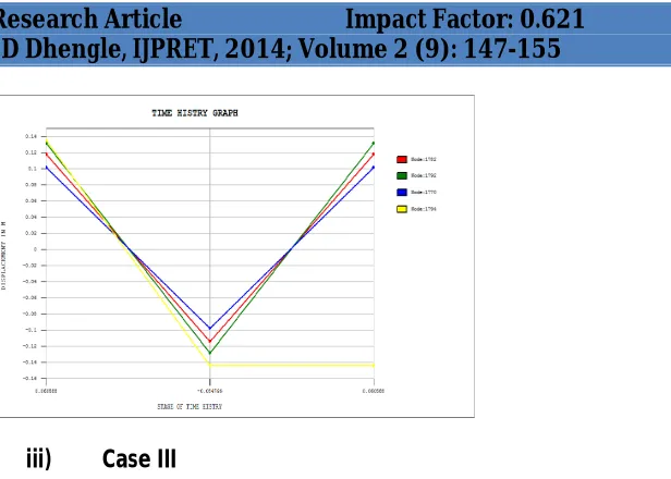
152 iii) Case III
Figure 4: Horizontal Displacement of Structure for Different Cases.
i) Case I
Available Online at www.ijpret.com
153 iii) Case III
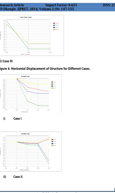
Figure 5: Vertical Displacement of Structure For Different Cases.
The maximum vertical displacement of about -2.217 mm was obtained for case I at nearest point of structure from tunnel, where horizontal displacement was 1.865 mm . In case II maximum vertical displacement occurred was -14.248 mm and horizontal displacement was 0.407 mm . for case III maximum vertical and horizontal displacements were 144.172 mm and -93. 413 mm respectively. The details of results are present below in tabular format as shown in table .4
Table 4: Summary of Results Obtained From Analysis Cases.
i) Case I
Division Distance Displacement (mm)
Structural Effect Check Adjacent Structure (Left)
10 M Horizontal 1.865
Vertical -2.217
30 M Horizontal 1.865
Vertical -1.044
Adjacent Structure (Right)
20 M Horizontal -0.852
Vertical -1.218
40 M Horizontal -0.848
Available Online at www.ijpret.com
154 ii) Case II
Division Distance Displacement (mm)
Structural Effect Check Adjacent Structure (Left)
10 M Horizontal 0.190
Vertical -14.248
30 M Horizontal 0.243
Vertical 1.849
Adjacent Structure (Right)
20 M Horizontal 0.407
Vertical -12.186
40 M Horizontal 0.345
Vertical 2.843
iii) Case III
Division Distance Displacement (mm)
Structural Effect Check
Adjacent Structure (Left)
10 M Horizontal -93.413
Vertical 118.169
30 M Horizontal -93.299
Vertical 131.473
Adjacent
Structure (Right)
20 M Horizontal -61.102
Vertical 101.253
40 M Horizontal -60.335
Vertical -144.172
Available Online at www.ijpret.com
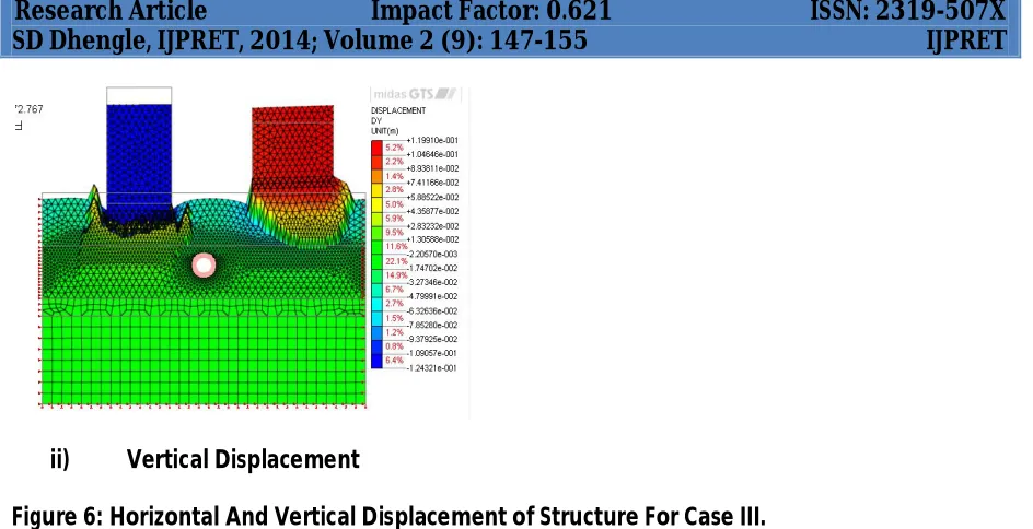
155 ii) Vertical Displacement
Figure 6: Horizontal And Vertical Displacement of Structure For Case III.
4. Concluding Remarks
It was observed that maximum displacement occurred at a point closer to tunnel excavation. Differential settlement occurred in case of vertical displacement. Also displacement was maximum in case of high rise building and less influence on low rise building. Under seismic loading condition tunnel survived but structure over which was damaged. It was found that at the upperearth surface the reaction to earthquake waves might lead to higher amplitudes of acceleration.
REFERENCES
1. Abdel, M. M., Rowe, R. K. and Lo, K. Y. (2002). “3D effects of surface construction over
existing subway tunnels.” The International Journal of Geomechanics., Volume 2, Number 4, 447–469.
2. Azadi, M. (2007). “The impact of underground tunnel excavation on adjacent buildings
during earthquake case study: Shiraz underground, Iran,. “electronics journal of geotechnical engineering.”
3. Mallika, S., Srividya, A. and Venkatachalam, G. (2012). “Uncertainty modelling and limit
state reliability of tunnel supports under seismic effects.”IJRET., http://www.ijret.org/.
4. Sliteen I., Mroueh, H. and Sadek, M. (2000).“Three-dimensional modeling of the behavior of