Available Online at www.ijpret.com 70
INTERNATIONAL JOURNAL OF PURE AND
APPLIED RESEARCH IN ENGINEERING AND
TECHNOLOGY
A PATH FOR HORIZING YOUR INNOVATIVE WORK
LIGHT- WEIGHT MACHINE GUN OPTICAL SIGHT
RAO PN1, SHRIVASTAVA SK2, LIKHITHA CH3, NAGAMANI R41. Retired Scientist ,Research Centre Imarat, Hyderabad, AP– 500069, India 2. Department of Physics, Bundelkhand University, Jhansi, UP - 284128, India 3. MLR Institute of Technology, Hyderabab-5000043, India.
4. National Institute of technology, Warangal, TS-506004, India.
Accepted Date: 13/11/2014; Published Date: 01/12/2014
\
Abstract: The optical design of the smallest day use telescopic sight in the 0.4μm to 0.7 μm wavelength range for mounting on solider light – weight machine gun is presented. It is a 2X. Sight with an objective focal length of 53082mm and the combined focal length of eyepiece – erector is 26.13mm.the field – of view of the sight in object space is 15 degrees and the apparent field is 30 degrees. The vertex to vertex length of the telescopic sight is 260.15 mm. The eye relief or eye safe distance of sight is 54.2 mm. The telescopic sight acquires and recognizes 2 -400 meter distant ambient illuminated military targets of soldier interest in warfare. All the optical surfaces of optics are spherical the physical dimensions of the sight for viewing and aiming enemy military targets illuminated in day light are dimensioned so that it can be mounted to light – weight machine gun with the use of mounting brackets and hardware of a standard size and spacing.
Keywords: Visible spectrum, day light illuminated targets, soldier light- weight machine gun sight and compact telescopic sight.
Corresponding Author: DR. P. NAGESWARA RAO
Access Online On:
www.ijpret.com
How to Cite This Article:
Rao PN,IJPRET, 2014; Volume 3 (4): 70-81
Available Online at www.ijpret.com 71 INTRODUCTION
Light- weight machine gun (LMG) is intended to be carried along with several belts of ammunition by individual soldier in combat and to deliver sustained firepower during enemy engagements. In a close quarter combat ,typically in the ranges of 2 – 800 meters, soldiers are required to rapidly acquire , identify and accurately fire an enemy targets. Soldiers use weapon mounted optical sights that works in visible light to assist in the aiming process during day time mission. In target shooting, the moving target is not a target for very long. The soldier must react to the initial vision of the target, bring the gun to sighting position, locate the target in the sight, fine tune the aiming the gun on the enemy target through the sight and fire. These activities must take place in time frame of a second or less. One of the most critical of these activities is target acquisition within the sight. That is, it is not enough merely to the soldier to see the target and shoot. Reliable accuracy is required actually finding the target within the gun sight. This is called target acquisition. Thus it is required to minimize the time or maximize the speed with which the target can be acquired within the sight. the quicker this can be done , the quicker the later steps of actually refining the aim and pulling the trigger can be accomplished .Soldier sees the visible target with a naked eye and direct the weapon towards the visible target. The sights used by military are to be short, light weight and small so that they are integral part of the weapon. These requirements are met by telescopic sights and can be mounted on a gun. The telescopes magnify the area of scene or the target area and enhances the ability of soldier to aim the gun during combat mission.. In addition to magnification, telescopic sights provide sufficiently bright images of dimly lighted distant military targets to the soldier under bright or dim light and against light or dark back ground conditions. The targets which the human eye cannot see, shall be seen through telescopic sight.
Refractive optics for telescopic sight is used in a wide variety of applications to obtain increased magnification of scene. In one common application, a viewing and aiming optics is affixed to the upper side of a small arm, in our case, soldier light–weight machine gun. The soldier sights through the viewing and aiming optics to acquire a target and aim the LMG towards the target to increase the likely hood of hitting the target with a bullet fired from the LMG. The telescopic sight for LMG sight will have limited field –of- view and magnification. The field –of –view and magnification are interlinked for such optics the larger the magnification, the smaller the field of view and vice versa. The field –of- view is smaller than the unaided eye.
Available Online at www.ijpret.com 72 -400 meters to the targets, the soldier is more effective in viewing and aiming the target with a moderate magnification of2x -6x magnification using one eye.
The physical dimensions of telescopic sight for viewing and aiming are important to maintain so that it can be mounted to LMG with the use of mounting brackets and hardware of a standard size and spacing. Light rays in 0.4 μm to 0.7 μm wavelength band reflected or emitted from an observed distant ambient illuminated target enter the telescopic sight of soldier LMG through a fixed objective portion passes through each optical element of the telescopic sight and exit the optics through eyepiece for viewing by the soldier. The lens design of telescopic sight for LMG delivers a resolution better than 1.0 minutes of arc in eye relief space for day use (or photopic use) for both magnification and field –of- view when the soldiers eye is at an eye relief distance of >25.0 mm The 1.0 minutes of arc resolution mentioned is also the limiting resolution of human eye of observer under best working conditions. Since the best conditions are not prevailed in ware field, the telescopic sight is designed for 2.0 minutes of arc resolution.
The telescopic sight also delivers long eye relief to accommodate eye guard made of resilent material which protects the soldier eye from LMG recoil. The publication presents the optical design and design data of 260.15 mm vertex to vertex length , 15 degrees field- of –view , 2x, sixteen element telescopic sight for mounting on soldiers lmg. The reticle is incorporated in the image plane of objective lens the design uses five optical glasses and sixteen lenses. The all spherical optical design delivers an eye relief of 54.2 mm. The all spherical optics is preferred here because it is easy s easy to fabricate and test the spherical optics .This is an added advantage when the required number of sights are in thousands. The optical design results 40 arc seconds on – axis and off- axis parallax errors due to the targets at different ranges. The optical design places the equal diameter lenses at equal distance from the centre of optical path of the sight for minimum deviation of Centro gravity of the sight so that the minimum bore sighting error appears between sight and gun barrel after mounting the sight on LMG
1. Requirements of telescopic sight for mounting on soldiers LMG
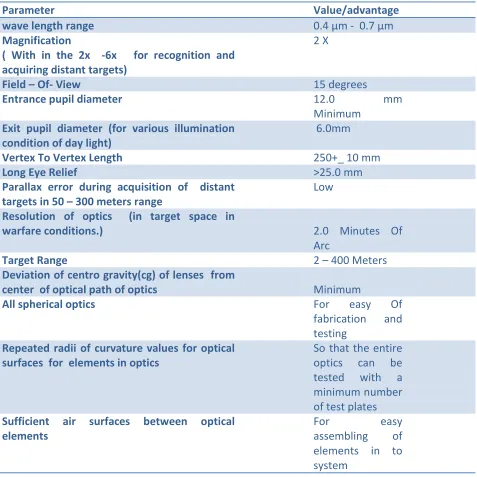
Available Online at www.ijpret.com 73 Table 1: Requirements of telescopic sight
Parameter Value/advantage
wave length range 0.4 μm - 0.7 μm
Magnification
( With in the 2x -6x for recognition and acquiring distant targets)
2 X
Field – Of- View 15 degrees
Entrance pupil diameter 12.0 mm
Minimum Exit pupil diameter (for various illumination
condition of day light)
6.0mm
Vertex To Vertex Length 250+_ 10 mm
Long Eye Relief >25.0 mm
Parallax error during acquisition of distant targets in 50 – 300 meters range
Low
Resolution of optics (in target space in
warfare conditions.) 2.0 Minutes Of
Arc
Target Range 2 – 400 Meters
Deviation of centro gravity(cg) of lenses from
center of optical path of optics Minimum
All spherical optics For easy Of
fabrication and
testing Repeated radii of curvature values for optical
surfaces for elements in optics
So that the entire
optics can be
tested with a
minimum number of test plates Sufficient air surfaces between optical
elements
For easy
assembling of
Available Online at www.ijpret.com 74 Figure 1: Typical soldier LMG
3.0 Configuration of telescopic sight for LMG mounting
The soldiers’ telescopes for shooting are erected class of focal systems with long eye relief. The telescopic sight is constructed with an objective lens , a reticle in the image plane of the objective , an erector lens with an aperture stop in the object space of the erector and an eyepiece. The focal lengths of objective, erector and eyepiece of telescopic sight of vertex to
vertex length of 250+ -10mm formounting on soldiers LMG are shown in Table2.
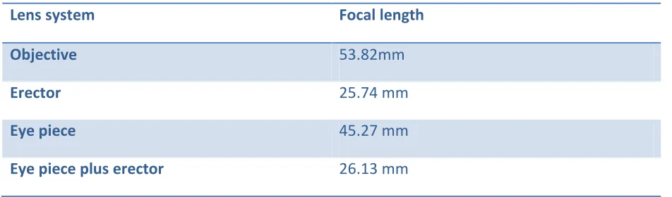
Table 2: Focal length of Objective, Erector and Eye piece
Lens system Focal length
Objective 53.82mm
Erector 25.74 mm
Eye piece 45.27 mm
Eye piece plus erector 26.13 mm
4.0 System design of telescopic sight
Available Online at www.ijpret.com 75 sight make the focal lengths of erector and eyepiece smaller than objective. In view of the desired long eye relief, the aperture stop is considered in between in between reticle and erector first lens the aperture stop location at this position provides long eye relief and place the elements in the optical path of sight at a minimum deviation position of CG of telescopic optics [1-3].
4.1Aberration corrections of telescopic sight Optical glasses for sight
As large number of sights is required, readily available and low cost optical glasses are considered in the optical design of telescopic sight for LMG. The number of optical glasses used in the sight is restricted to five considering their future availability and to store the glass stock for future needs. Design efforts are made to use low density optical glasses in order to reduce the weight of the telescope optics.
4.1.1 Optical design of objective lens
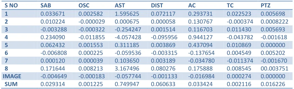
Available Online at www.ijpret.com 76 objective lens. The efforts are not made in the design of objective to reduce the distortion .It is decided to correct the distortion of objective in the design of telescope reticle. [4-8]. The well corrected objective lens for telescopic sight has a positive meniscus element in front ,a first biconvex-negative meniscus cemented doublet and second negative meniscus- biconvex cemented doublet behind. It covers a 15 degrees field of view at 53.82 mm focal length. The Seidel aberrations of objective including a reticle in 0.4 μm - 0.7 μm wave length range is given in Table 3.
Table 3: Seidel aberrations of objective including reticle in 0.4 μm-0.7 μm wave length range
S NO SAB OSC AST DIST AC TC PTZ
1 0.033671 0.002582 1.595625 0.072117 0.293731 0.022523 0.005698
2 0.010224 -0.000029 0.000675 0.000058 0.130767 -0.000374 0.0008222
3 -0.003288 -0.000322 -0.254247 0.001514 0.116703 0.011430 0.005693
4 0.234090 -0.011855 -4.057428 -0.095956 0.944127 -0.043782 -0.001618
5 0.062432 0.001553 0.311185 0.003869 0.437094 0.010869 0.000000
6 -0.006808 0.000225 -0.059536 -0.003315 -0.137654 0.004549 0.005202
7 0.000120 0.000039 0.103650 0.003189 -0.034780 -0.011374 -0.001670
8 0.171644 0.008213 3.167496 0.080276 0.175888 0.008545 00.003751
IMAGE -0.004649 -0.000183 -0.057744 -0.001133 -0.016984 0.000274 0.000000
SUM 0.029314 0.001225 0.749947 0.060633 0.033424 0.002116 0.016226
4.1.2 Erector lens
Available Online at www.ijpret.com 77 positive meniscus and Plano convex lenses. The erector covers a 15 degrees field of view at 25.74 mm focal length. The Seidel aberrations of the erector lens are shown in table.
4.1.3 Eyepiece
The eye pieces are designed for wide angles and small apertures (4.0mm) for different eye safe distances. The conventional eye pieces have optical elements ranging from two to eight. The eye relief of these eyepieces varies from 0.8 to 1.5 times the focal length. They all designed for unit or one inch focal length. The eyepiece for use in telescopic sight for mounting on lmg shall have a focal length of 45.26 mm and an eye relief of not less than 50.0 mm. A long focal length eyepiece is constructed with two cemented doublets and a single negative lens that meets the requirements of telescopic sight for mounting on soldiers LMG .
4.1.4 Aberration corrections of erector and eye piece
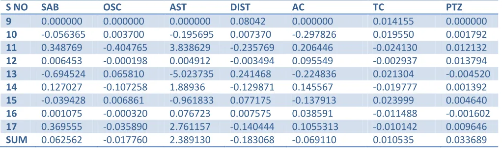
The erector and eye piece are designed separately for minimum on–axis and off- axis aberrations. The Seidel values qualified the lens systems for Petzval sum and two color aberrations. They are improved for coma and astigmatism using bending technique. The actual aberrations are calculated by trigonometric ray trace .Bending and optical glassy substitutions are implemented for satisfactory solution for aberrations of these systems. The corrected erector and eyepiece are combined into a single system with aperture stop in the image space of eyepiece and erector combination and again corrected for aberrations of the combined system [4-8]. The combined focal length of eyepiece and erector is 26.13426mm. The Seidel aberrations of erector and eyepiece combination are calculated by ray tracing from eye end and are shown in Table4.
Table 4(a): Seidel aberrations of Eye piece plus erector from Eye piece end in 0.4 μm - 0.7 μm wave length range
S NO SAB OSC AST DIST AC TC PTZ
9 0.000000 0.000000 0.000000 0.08042 0.000000 0.014155 0.000000
10 -0.056365 0.003700 -0.195695 0.007370 -0.297826 0.019550 0.001792
11 0.348769 -0.404765 3.838629 -0.235769 0.206446 -0.024130 0.012132
12 0.006453 -0.000198 0.004912 -0.003494 0.095549 -0.002937 0.013794
13 -0.694524 0.065810 -5.023735 0.241468 -0.224836 0.021304 -0.004520
14 0.127027 -0.107258 1.88936 -0.129871 0.145567 -0.019777 0.001392
15 -0.039428 0.006861 -0.961833 0.077175 -0.137913 0.023999 0.004640
16 0.001075 -0.000320 0.076723 0.007575 0.038591 -0.011488 -0.001602
17 0.369555 -0.035890 2.761157 -0.140444 0.1055313 -0.010142 0.009646
Available Online at www.ijpret.com 78 Table 4(b): Seidel aberrations of Eye piece plus erector from Eye piece end in 0.4 μm - 0.7 μm
wave length range
S NO SAB OSC AST DIST AC TC PTZ
18 0.003076 0.000219 1.046486 0.061624 -0.3222220 0.022963 0.004641
19 -0.006738 -0.000263 -0.888833 -0.023710 -0.484589 -0.021503 -0.001222
20 0.131395 0.002213 2.497504 0.029742 0.412015 0.006940 0.007026
21 -0.000311 -0.000069 -1.038344 -0.003381 0.032958 0.007363 0.0068547
22 -0.047101 -0.001184 -1.994671 -0.027347 -0.627517 -0.015778 -0.001227
23 0.093463 0.001410 1.425266 0.012889 0.586667 0.008852 0.001925
24 -0.089246 -0.001326 -1.319164 -0.011721 -0.569446 0.008459 -0.001760
25 0.030443 0.000135 0.040316 -0.000301 0.328252 0.001460 0.001193
SUM 0.114981 0.001100 -0.321439 0.037847 0.000561 0.001837 0.015044
4.1.5 Optical design of telescopic sight
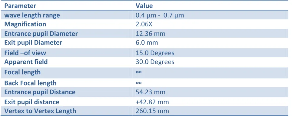
The individually corrected objective reticle combination and eyepiece –erector combination are integrated into a telescopic sight. An axial ray tracing through the sight provides the focal length, back focal length, entrance and exit pupil distances of sight. The exit pupil distance is the eye relief of the sight. The axial and field bundle ray trace gives the apertures of lens elements of sight. The optical characteristics, optical configuration and optical design data of complete telescopic sight, objective -retile combination, erector, eyepiece and eyepiece- erector combination are shown in Table5, figure 2and Table 6.
Table 5(a): optical characteristics of telescopic sight
Parameter Value
wave length range 0.4 μm - 0.7 μm
Magnification 2.06X
Entrance pupil Diameter 12.36 mm
Exit pupil Diameter 6.0 mm
Field –of view 15.0 Degrees
Apparent field 30.0 Degrees
Focal length ∞
Back Focal length ∞
Entrance pupil Distance 54.23 mm
Exit pupil distance +42.82 mm
Available Online at www.ijpret.com 79
Number of lenses 016
Number of optical glasses 05
Reticle In the objective image plane
Targets military ambient illuminated targets of soldier interest in combat at a range of 50 – 400 meters
Table 5(b): optical characteristics of telescopic sight
Lens system Entrance pupil Distance
Exit pupil distance
Objective -150.0 mm 25.48mm
Eye piece plus erector
-54.0mm +0.351229mm
Figure 2: optical characteristics of telescopic sight
Table 6(a): optical design data of telescopic sight
LENS GLASS R1 R2 R3 R4 R5 R6 R7 R8 CT CA
I LAC
697562
72.10 VEX
500.0 CAV
6.0 16.0
II BSC
510644
59.3 VEX
49.5 VEX
10.0 16.0
III DEDF
717295
49.5 CAV
∞ 5.0 16.0
IV DEDF
717295
80.3 VEX
47.7 CAV
1.5 14.5
V BSC
510644
47.7 VEX
90.0 VEX
Available Online at www.ijpret.com 80 CT= Centre thickness, CA= clear aperture
ALL THE DIMENSIONS ARE IN MM
Table 6(b): optical design data of telescopic sight
LENS GLASS R9 R10 R11 R12 R13 R14 R15 R16 R17 CT CA
VI BSC
510644
35.0
CAV 50.0
CAV
8.0 14.0
VII DEDF
717295
50.0
VEX
90.0
VEX
3.0 14.0
VIII DEDF
717295
300.0
CAV 17.0
CAV
3.0 14.0
IX BK7
517642
7.0
VEX 24.7
VEX
6.0 14.0
X MBC
572577
30.0
CAV
30.0
VEX
6.0 14.0
XI DEDF
717295
30.0
CAV
∞ 1.5 14.0
CT= Centre thickness, CA= clear aperture
ALL THE DIMENSIONS ARE IN MM
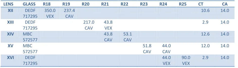
Table 6(c): optical design data of telescopic sight
LENS GLASS R18 R19 R20 R21 R22 R23 R24 R25 CT CA
XII DEDF 717295
350.0 VEX
237.4 CAV
10.6 14.0
XIII DEDF
717295
217.0 CAV
43.8 VEX
2.9 14.0
XIV MBC
572577
43.8 CAV
53.1 CAV
12.6 14.0
XV MBC
572577
51.8 CAV
44.0 CAV
12.0 14.0
XVI DEDF 717295
44.0 VEX
90.0 VEX
Available Online at www.ijpret.com 81 CT= Centre thickness, CA= clear aperture
ALL THE DIMENSIONS ARE IN MM
5.0 CONCLUSIONS
A sixteen element telescopic sight is designed for mounting on soldier light – weight machine gun. The telescopic sight consists of objective, erector and an eyepiece. The magnification, field- of – view entrance pupil diameter and exit pupil diameter of the optics are 2.06x, 15.0 degrees, 12.36 mm, 6.0mm respectively. The vertex to vertex length of the telescopic sight is 261.34mm. The telescopic sight is designed using only five optical glasses in sixteen elements. The telescopic sight images 2 -400 meter distant day time ambient illuminated military targets in objective image plane which is reimaged by erector lenses in the object plane of eyepiece. Soldier sees the images of distant targets through an eyepiece from a distance equal to the eye relief of 54.23mm. All the optical surfaces of telescopic sight are spherical. The optical design is unique in its optical characteristics.
REFERENCES
1. Cox. A “A System of Optical Design “, Focal Press, London, p 606, 1964.
2. Bruce H. Walker, Optical Engineering Fundamentals Second Edition, SPIE Press, Washington ,
Chapter 4 on Thin Lens Theory, pp 47-76, 2008.
3. Handbook of Optical Systems Vol3.Aberration Theory and Correction of Aberrations. Edited
by Herbert Cross, Wiely-VCH Verlag GmbH & Co, Weinheim, Chapter 29, 2007.
4. A. E. Conrady, Applied Optics and Optical Design Part 2, Dover Publication, New York,
pp640-661, 1960.
5. Rudolf King slake and R. Barry Johnson, Lens Design Fundamentals, pp 318-322, Elsevier,
Oxford, 2010.
6. Donald. H. Jacobs, Fundamentals of Optical Engineering, McGraw Hill, New York.pp381-389,
1943.
7. W. J. Smith,” Modern Optical Engineering “, McGraw-Hill. Inc., New York. pp 272-278;
pp247-256; pp 300-302; pp 324-325, 1966.
8. Daniel Malacara, Zacaris Malacara, Handbook of Optical Design. Second Edition, Marcel