Available Online at www.ijpret.com 47
INTERNATIONAL JOURNAL OF PURE AND
APPLIED RESEARCH IN ENGINEERING AND
TECHNOLOGY
A PATH FOR HORIZING YOUR INNOVATIVE WORK
COMMUNICATION PROTOCOL IMPLEMENTATION IN FPGA
BETTY GEORGE1,TINA RAJA2
1.PG Student [Applied Electronics], Dept. of ECE, MG University College of Engineering, Thodupuzha, Kerala, India.
2.Scientist/Engineer "SE", QDAC/QRAG/SR/ VSSC, Trivandrum, Kerala, India.
Accepted Date: 05/10/2015; Published Date: 01/11/2015
\
Abstract: - Protocols are needed for establishing communication between devices. The most
widely used protocols are UART and I2C. This paper proposes a new approach in implementation of these protocols along with a memory which could be implemented onto a FPGA which makes the implemented device capable of communicating with peripheral devices connected that have any one of the specified communication protocol such as UART or I2C protocol in it. UART is a serial communication protocol that includes a transmitter, receiver and baud rate generator. I2C is a less complex communication protocol that ensures connection between devices using two lines. The protocol implementation is done in ModelSim platform.
Keywords:FPGA, I2C, MODELSIM, UART
Corresponding Author: MS. BETTY GEORGE
Access Online On:
www.ijpret.com
How to Cite This Article:
Betty George, IJPRET, 2015; Volume 4 (3): 47-55
Available Online at www.ijpret.com 48 INTRODUCTION
UART is the abbreviated form of Universal Asynchronous Receiver Transmitter. Universal Asynchronous Receiver Transmitter is commonly included in microcontrollers and is designed to be used for various applications. UARTs are used for devices such as modems, wireless communication etc. It is a serial communication protocol which consists of a transmitter, receiver and baud rate generator. The transmitter converts the parallel data to serial fashion and then transmits it bit by bit. While the receiver receives the data in a serial manner and converts the data to parallel form. UART interface chip could follow various serial bus interface standards such as RS-232, RS-422 and RS-485.
I2C is the abbreviated for of Inter Integrated Circuit, offers very advanced feature; automatic multi-master capability. ADC (Analog-to-Digital Converter), EEPROM (Electrically-Erasable Programmable Read-Only Memory), DAC (Digital-to-Analog Converter), RTC (Real-time clocks), microcontrollers, sensors are largely available with I²C interface. The two I²C signals are serial data (SDA) and serial clock (SCL). There is no need of slave select even though the protocol could be used for any number of slaves. The slaves have a unique address which could be used for selection purpose. It is also bidirectional mode of communication. A Multi master criterion is also acceptable for the I2C protocol.
The microcontroller is embedded with many communication protocols. The communication protocol includes UART and I2C. The paper proposed is a forehand for the testing of microcontroller specified by PIC18F65XX. The test station includes UART (RS232) for the communication with FPGA. The UART and I2C interfaces implemented in FPGA are used to test the interfaces of the PIC microcontroller. The Device Under Test (DUT) is PIC microcontroller and test station is usually a PC. The basic structure of test system is as in Fig.1.
Available Online at www.ijpret.com 49 SOFTWARE ENIVORMENT
The implementation and synthesis of the main controller is done in ModelSim and Xilinx software platform. ModelSim is an HDL simulation environment developed by Mentor Graphics. Development of HDL design involves creating the working library, compiling of design, loading the simulator with design and running the simulation and debugging of results.
WORKING PRINCIPLE
UART
UART communication follows data frame that starts with start bit (logic “0”), 5-8 data bits, stop bit (“1”), parity bit (even or odd) and idle state. The data frame is given in Fig.2.
Fig. 2. Data Frame.
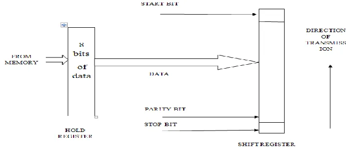
UART transmitter is used for conversion parallel data to serial for and its transmission long the line. The two type of registers used for the transmission process are the Transmit Shift Register and Transmit Buffer Register. As the name suggest, shift registers are used for the function of shifting in data and buffer registers are employed for temporary storage of data. Fig.3. illustrate the transmission of data through UART transmitter.
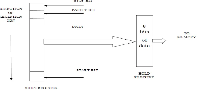
Available Online at www.ijpret.com 50 UART Receiver section consists of Receiver Shift Register and Receiver Buffer Register. FIG.4. shows the receiver section of the UART. Here the valid reception is marked by the reception of a start bit followed by data bits and parity bits. The reception termination is marked by stop bit.
Fig. 4. UART Receiver
I2C
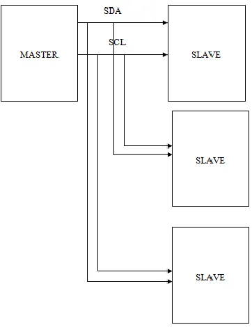
I²C is a multi-master protocol. The two signals used are SDA and SCL. The SDA line is used to carry data either from master or slave. The acknowledgement from the master in case of a read signal and an acknowledgement signal from the slave in case of the write signal and the data bit transfer to slave or master could be made possible using the SDA line. The clock is provided by the master through the SCL line. 7-bits slave addresses are used for the identification of slaves and initiation of transmission to it. The data rate could be 100 kbps, 400 kbps and 3.4 Mbps, respectively called standard mode, fast mode and high speed mode.
Available Online at www.ijpret.com 51 Fig. 5. I2C Basic Block Diagram
IMPLEMENTATION AND SYNTHESIS
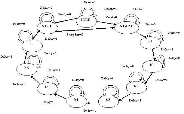
UART transmitter and receiver are realized using state machines. The state machines provide the functionality of the implemented design. Fig.6. shows the transmitter state machine. Eleven states are defined in the state machine. Idle state is where no operation occurs and when a start bit polled obtains a 0 value, the transmission is initiated and a stop bit marks the end of transmission.
Available Online at www.ijpret.com 52 UART receiver state machine is given in Fig.7. The state machine of receiver also poses eleven states. The idle state is where the reception is polled for. A change in reset value marks the reception operation. Start bit is received and when it is logic 0, the state is changed to b0 where the first bit among the 8 bit is received and stored and thus 8 bits are recei ved and stop bit indicates termination of reception process.
Fig. 7. Reciever state machine
Available Online at www.ijpret.com 53 Fig. 8. I2C state machine
RESULT
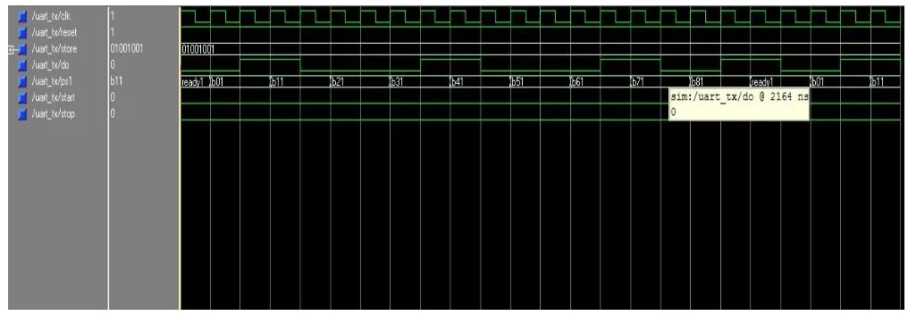
UART transmitter VHDL implementation plot is given in Fig.9. Here store value is the value that needed to be transmitted and the state are defined by ready, b01, b11, b21, b31, b41, b51, b61, b71, b81. The output value that is transmitted is given by d0. Here the parallel data being transmitted in serial fashion is depicted.
Fig. 9. UART Transmitter.
Available Online at www.ijpret.com 54 Fig. 10. UART Receiver
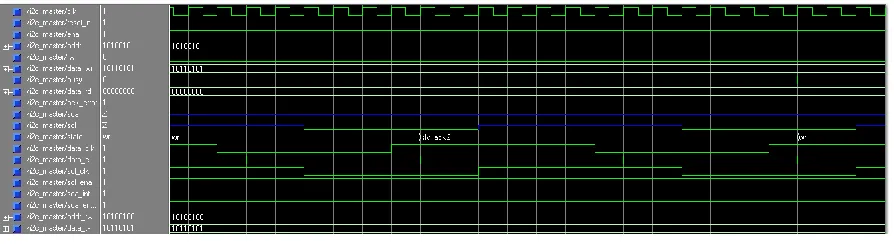
There are two operation carried out using the I2C communication protocol. One is read operation and other is write operation. Fig.11 shows the I2C write operation where master writes onto a slave. Here the logic is implemented and it is not connected to any slave device, so the sda and scl lines are not defined. The state denotes that a slave acknowledgement is acquired as a result of the completion of write operation cycle.
Fig. 11. I2C Write operation
Fig.12 shows the read operation by I2C protocol. The state carried out is read as the concatenated value is read. The value is read from the slave but as the slave is not connected, the logic is implemented. Here a master controlled I2C is implemented.
Available Online at www.ijpret.com 55 CONCLUSION
Communication protocols that are widely used are implemented in HDL. UART and master controlled I2C are widely used for communication. The implemented design could be used to design an FPGA that could act as a controller for the testing of communication protocols of a microcontroller. The selectable frequency and baud rate for I2C and UART help the FPGA to test the microcontroller’s I2C and UART for different speeds. Extensive simulations were carried out to test the implemented modules.
REFERENCES
1. Dr G. B. Wakle, I. Aggarwal and S. Gaba, “Synthesis and Implementation of UART using VHDL Codes”, International Symposium on Computer, Consumer and Control, pp.1-3, June 2012.
2. Y. Wang and K. Song, “A New Approach to Realize UART,” in Electronic and Mechanical Engineering and Information Technology (EMEIT), International Conference, vol. 5, pp. 2749 – 2752, 2011.
3. T. P. Blessington, B. B. Murthy, G. V. Ganesh and T.S.R Prasad, “Optimal Implementation of UART-SPI Interface in SOC”, Devices, Circuits and Systems (ICDCS), International Conference, pp.673-67, 2012.
4. Philips Semiconductors, “I2C Manual,” March 2003.