Organized by C.O.E.T, Akola. Available Online at www.ijpret.com
151
INTERNATIONAL JOURNAL OF PURE AND
APPLIED RESEARCH IN ENGINEERING AND
TECHNOLOGY
A PATH FOR HORIZING YOUR INNOVATIVE WORK
FREE VIBRATION ANALYSIS OF RECTANGULAR PLATES USING FINITE ELEMENT
PROCEDURES
R. R. GADPAL, M. D. KULKARNI
Department of Applied Mechanics, Govt. Polytechnic, Arvi , Dist.(Wardha)
Accepted Date: 05/09/2017; Published Date: 10/10/2017
Abstract:
The generalised problem in free vibration analysis of any structure is that of evaluating an eigenvalue ωmn, which is a measure of the frequency of vibration together with the corresponding eigenvector x indicating the mode shape. This presentation consists of determination of fundamental vibration frequenciesof an isotropic rectangular thin plate. The stiffness and mass matrices are determined by the finite element method using Kirchhoff plate theory. Numerical results obtained from FEM of the simply supported rectangular plate show good agreement with those determined by classical method. Moreover the results showed that the variation of plate thickness does not affect the frequency parameter.
Keywords:
Free vibration analysis, Fundamental natural frequencies, Mode shapes, Stiffness and mass matrices, Kirchhoff plate theory, Finite Element Method..
Corresponding Author: R. R. GADPAL
Co Author: - M. D. KULKARNI
Access Online On:
www.ijpret.com
How to Cite This Article:
R. R. Gadpal, IJPRET, 2017; Volume 6 (2): 151-162
PAPER-QR CODE
SPECIAL ISSUE FOR
INTERNATIONAL LEVEL CONFERENCE
"ADVANCES IN SCIENCE,
Organized by C.O.E.T, Akola. Available Online at www.ijpret.com
152
INTRODUCTION
Free vibration analysis is often required for most of the plate like structural elements in the field of civil, mechanical, automobile, aerospace, optical, marine, nuclear and structural engineering. The differential characteristics in free vibration analysis enable engineers to design better and lighter structures. In case of complicated shapes generally it is difficult to obtain an accurate analytical solution for the structures with different sizes, various loads and different material properties. Hence, we need to apply on approximate numerical methods for obtaining appropriate solutions of static and dynamic problems.
The finite element method is widely used and powerful numerical method. The basic concept of finite element method is to discretise the continuum structure into elements called finite elements. A displacement function is associated with each finite element. Actually, elements are connected together all along the common edge and not at nodes only. In finite element method, the displacements at the nodes are treated as primary unknowns. These nodal displacements are obtained by solution of simultaneous equations which arise when conditions of minimum total potential energy of the structure are applied. If the nodal displacements are known, then other dependent quantities can be found at any location of the structure. Thus, from stress/strain properties of the material of the structure, one can determine the behaviour of the node in terms of the properties of every other element in the structure. The finite element method of structural analysis enables the designer to find stress, vibration and thermal effects during the design process and to evaluate design changes before the construction of a possible prototype.
II LITERATURE REVIEW
The literature of vibration problems is quite large, both for theoretical aspects and numerical algorithms, and only a small fraction of it can be cited. Hughes T.J.R. [1], Bathe K. J. [2] and Kardestuncer H. [3] have written extensive discussions about vibration problems in their Finite Element Books. Wilkinson J.H. [4] wrote a book about the algebraic vibration problem in 1965. Bathe K. J. and Wilson E.L. [5] published a paper on solution methods for vibration problems in structural mechanics in 1973. In 1980, Parlett B.N. [6] introduced the method for solution of the symmetric vibration problem. In 1984, Jennings A. [7] wrote about eigenvalue methods for vibration analysis. Tanaka et.al. [8] studied the integral equation approach for free vibration problems of elastic plate structures in 1988. Cheung Y.K. and Leung A.Y.T. [9]. published a book on finite element methods in dynamics in 1991. In 1997, Karunasena and Kitipornchai [10] determined the free vibration analysis of shear deformable triangular plate element.
In the current century researchers have developed the new methods for free and forced vibration analysis of plate structures. Moon and Choi [11] have formulated transfer dynamic stiffness co-efficient method vibration analysis of frame structure. Taking this as base, Myang [12] has developed the finite element-transfer stiffness coefficient method for free vibration analysis of plate structures. Liew et.al. [13] have investigated a mesh-free Galerkin method for free vibration analysis of unstiffened and stiffened corrugated plates. Lu et.al. [14] have investigated differential quadrature method for free vibration analysis of rectangular Kirchhoff plates with different boundary conditions.
Organized by C.O.E.T, Akola. Available Online at www.ijpret.com
153
frequencies of rectangular plate by solving eigenvalue problem. Numerical results of simply supported rectangular plate showed that these present method can be successfully applied to the free vibration analysis of any thin rectangular plate structure. In the case of varying thickness of rectangular plate structures natural frequencies parameter error varies and it is constant with increase in the plate thickness.III. FINITE ELEMENT FORMULATION
1. Kirchhoff Plate Theory
The classical thin plate theory developed by Love- Kirchhoff is based on the following assumptions:
(i) Middle plane of the plate remains unstretched.
(ii) Normal to the middle plane at a point, before bending, remains straight and normal to the middle plane after bending. See fig.1 (b) and (c).
(iii) Normal is inextensible. Hence the strain in thickness direction (ɛzz) is absent.
(iv) Normal stress in thickness direction is neglected. Thus, both, stress σzz and strain ɛzz are treated as absent. This is inconsistent. But, it is accepted in Love’s assumption.
(v) Plate is defined by middle plane. All unknowns are referred to a point on the middle plane.
Fig.1. Plate and displacements
Considering the various assumptions mentioned above, the displacement model for thin plate is written as
U(x,y,z) = - z (x,y)
V(x,y,z) = - z (x,y)
W(x,y) = w(x,y) ... (1)
Organized by C.O.E.T, Akola. Available Online at www.ijpret.com
154
ɛxx = - z = z χxɛyy = - z = z χy
γxy = -2z = z χxy
ɛzz = 0, γxz = 0, γyz = 0 ...(2)
Hence the generalised strains (curvatures in this case) are written as
{χ }= = (-) ... (3)
The stresses in xy plane are related to strains in terms of elasticity matrix of plane stress condition are
= ... (4)
Stresses Eq.(4) vary linearly along thickness direction. Hence, the stress resultants (bending and twisting moments in this case) are obtained as
[ Mx My Mxy ]T = [ ]T dz ...(5)
Substituting stresses in terms of strains Eq.(4) and strains in terms of curvatures Eq.(2) and carrying out integral in z direction
= D ... (6)
Where, D = and is called flexural rigidity of the plate.
Organized by C.O.E.T, Akola. Available Online at www.ijpret.com
155
... (7)
Where q is the transverse distributed loading on the plate and and are the transverse shear loads.
Substituting the moment-curvature expressions in the Eq. (7) and solving for and , and substituting the results into the Eq. (6) above , the governing differential equation for isotropic thin plate in bending is obtained as:
D = q ... (8)
2. Formulation for 4 - noded rectangular element
Fig.2 shows a rectangular element of size a b lying in xy plane. It has four corner nodes. Each node is associated
with transverse displacement w and two derivatives and . The element vector {δe} of 12 x 1 size is defined as
{δe} = { w1 1 1 ... w4 4 4 }T ...(9)
Fig.2. Element and Polynomial Terms
Hence the element has 12 degrees of freedom and the displacement function of the element can be represented by a polynomial is having twelve terms defined as:
Organized by C.O.E.T, Akola. Available Online at www.ijpret.com
156
This function is a complete cubic to which have been added two quadratic terms x3y and y3x which are symmetrically placed in Pascal’s triangle. This will ensure that the element is geometrically invariant. It is convenient to develop the formulation in terms of shape functions. Based on the polynomial in Eq.(10) . Meghre and Kadam[15] have developed explicit expressions for twelve shape functions in terms of r and s such thatr = x/a and s = y/b ... (11)
Table 1 . Shape Functions
Node Shape
Function
Multiplier Coefficients of Polynomial Terms
1 r s r2 rs s2 r3 r2s rs2 s3 r3s rs3
1 N1 1 1 0 0 -3 -1 -3 2 3 3 2 -2 -2
N2 a 0 1 0 -2 -1 0 1 2 0 0 -1 0
N3 b 0 0 1 0 -1 -2 0 0 2 1 0 -1
2 N4 1 3 1 0 -2 -3 -3 0 2 2
N5 a -1 0 0 1 1 0 0 -1 0
N6 b 0 1 0 0 0 -2 0 0 1
3 N7 1 -1 0 0 3 3 0 -2 -2
N8 a 0 0 0 -1 0 0 1 0
N9 b 0 0 0 0 -1 0 0 1
4 N10 1 1 3 0 -3 -3 -2 2 2
N11 a 1 0 0 -2 0 0 1 0
N12 b 0 -1 0 0 1 1 0 -1
These shape functions are given in Table 1. As an example, shape function N11 is written as
N11 = a ...(12)
The displacement variation in terms of shape functions is written as
w(x,y) = [N1 N2 N3 ... N12] {δe}
w(x,y) = [N ] {δe} ... (13)
Organized by C.O.E.T, Akola. Available Online at www.ijpret.com
157
{χ } = = [B ] {δe} = [B1 B2 B3 ... B12] {δe} ... (14)A typical sub-matrix [B]i is
= (-) ... (15)
Eq.6 gives relation between moments and curvatures. The flexural strain energy in the element is written as
U = [D] {χ} dA = [M] dA ... (16)
Substituting for {χ} and [M] from Eqs.14 and 16, we get
Ue = {δe} ... (17)
Thus, the element stiffness matrix is
[ke] = ...
(18)
Stiffness matrix of size 12 x 12 can be evaluated using numerical integration. However, an explicit form of stiffness matrix is given in this presentation. A typical element in ith row and jth column of stiffness matrix is expressed as
keij = ... (19a)
keij = ... (19b)
keij =
Organized by C.O.E.T, Akola. Available Online at www.ijpret.com
158
After carrying out explicit integrations, the stiffness matrix is expressed in compact form as[ke] = [L] [L] ... (20)
Matrices [K1], [K2], [K12] and [K3] are given in Table 2. [L] is a diagonal matrix having diagonals as
[L] = diagonals [ 1 a b 1 a b 1 a b 1 a b ] ... (21)
Table 2 : Explicit Form of Element Stiffness Matrix [15]
[K1] =
Organized by C.O.E.T, Akola. Available Online at www.ijpret.com
159
[K12] =[K3] =
Element mass matrix is derived as
[m]e = ρh [N]T[N] dA ...(22)
The element and mass matrices are assembled in to get global matrices.
The equation of motion of the plate can be written as:
[K]g ωmn2 [M]g ... (23)
IV NUMERICAL EXAMPLE
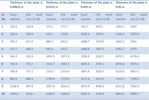
Example 1: The simply supported rectangular plates of size 0.6 m x 0.4 m of varied thicknesses from 6.25 mm to 50
mm (double the thickness each time) are to be analysed for free vibration. Determine first ten natural frequencies of the plate on the basis of above formulation. Take E for aluminum = 70 GPa, Density ρ = 2700 kg/m3, Poisson’s ratio ν = 0.3.
Organized by C.O.E.T, Akola. Available Online at www.ijpret.com
160
Using standard finite element procedure [15], we obtain the stiffness and mass matrices as per Eqs.20 and 22 and determine first ten natural frequencies with the help of developed program. The results of the same are tabulated in Table 3.Table 3: First Ten Natural Frequency Values (Hz)
Thickness of the plate is 0.00625 m
Thickness of the plate is 0.0125 m
Thickness of the plate is 0.025 m
Thickness of the plate is 0.05 m
Sr. No.
Exact solution
FEA mesh size (12 x8)
Exact solution
FEA mesh size (12 x8)
Exact solution
FEA mesh size (12 x8)
Exact solution
FEA mesh size (12 x8)
1 136.5 135.8 273.1 271.7 546.2 543.5 1092.5 1087
2 262.6 259.9 525.2 519.8 1050.4 1039.7 2100.9 2079.4
3 420.1 417.6 840.3 835.2 1680.7 1670.5 3361.5 3341
4 472.7 466.8 945.4 933.7 1890.8 1867.5 3781.7 3735
5 546.2 535.9 1092.5 1071.9 2185.0 2143.7 4370.1 4278.4
6 756.4 733.7 1512.7 1467.5 3025.4 2935.1 6050.8 5870.2
7 766.9 757.1 1533.7 1514.4 3067.4 3028.7 6134.8 6057.5
8 892.9 888.3 1785.8 1776.6 3571.6 3553.3 7143.3 7106.5
9 1018.9 997.8 2037.9 2024.2 4075.9 4048.3 8151.8 7982.4
10 1050.4 1012.1 2100.9 2263.4 4201.9 4526.9 8403.9 8096.7
Frequency Parameter Equation
= ωmn ) ...
(24)
Table 4: Frequency ParameterValues (Hz)
S.No. Thickness 0.00625 m Thickness 0.0125 m Thickness 0.025 m Thickness 0.05 m
Organized by C.O.E.T, Akola. Available Online at www.ijpret.com
161
Frequency Parameter is calculated based on the results obtained from exact solution as well as FEA solutions. In case of rectangular element have four nodes, each node three degrees of freedom. The mesh size 12 x 8 means that the total number of elements 96. By using this analysis it has been concluded that the frequency parameter is carrying more weight with increasing the plate thickness. Illustrated results in Table 4 shows the frequency parameter values at different thickness. Here only fundamental natural frequency parameter variation is considered with varying its thickness.V CONCLUSIONS:
The approximate technique finite element method is used for analysing a rectangular plate based on the classical plate theory. In this paper free vibration analysis has been carried out for a rectangular plate. By varying the thickness of the plate it has been concluded that the frequency parameter is constant. The results showed current methodology solutions closely converged to the exact solutions. Increase in the thickness of plate does not affect the frequency parameter.
References:
1. Hughes T.J.R., “The Finite Element Method: Linear Static and Dynamic Finite Element Analysis”, Prentice Hall, Englewood Cliffs, NJ, (1987)
2. Klaus.-.Jurgen Bathe - Finite Element Procedures , Fourth Reprint, Prentice Hall of India Pvt. Ltd. (1997).
3. Kardestuncer H.,ed,- Finite Element Handbook, McGraw Hill, New York, (1987).
4. Wilkinson J.H.,- The Algebraic Eigenvalue Problem, Clarendon Press, Oxford, U.K., (1965)
5. Bathe K. J. and Wilson E.L. “Solution Methods for Eigenvalue Problem in Structural Mechanics”, International Journal for Numerical Methods in Engineering, Vol.6, No. 2, pp 213-226 (1973).
6. Parlett B.N.- “The symmetric Eigenvalue Problem”’ Prentice Hall of India Pvt. Ltd, Englewood Cliffs, NJ, (1980).
7. Jennings A.– “Eigenvalue Methods for Vibration Analysis”, Shock and Vibration Digest, Vol. 16, No.1 , pp 25 -33 (1984).
8. Tanaka M., Yamagiva K., Miyazaki K., Yeda T. - “Free Vibration Analysis of plate structures by boundary element Method, Engineering Analysis, Vol. 5, No. 4, pp 182-188 . Dec. 1988
9. Cheung Y.K. and Leung A.Y.T.,-“Finite Element Methods in Dynamics, Kluwer Academic Publishers, Dordrecht (1991).
10.Karunasena W. and Kitipornchai S.,- “Free Vibration of shear deformable general triangular plates. Journal of Sound and Vibration, Vol. 199, No.5 , pp 595-613 (1997).
Organized by C.O.E.T, Akola. Available Online at www.ijpret.com
162
12.Myung Soo Choi,- “Free Vibration Analysis of Plate Structures using Finite Element – Transfer Stiffness Coefficient Method”, KSME International Journal, Vol. 17, No.6, pp 805-815 , (2003)13.Liew K.M., Peng L.X., Kitipornchai S., -“Vibration Analysis of Corrugated Reissner-Mindlin plates using a free mesh Galerkin Method”, International Journal of Mechanical Sciences,Vol.51, Issues 9&10, pp 642-652, (2009)
14.Lu C.F., Zhang Z.C., Chen W.Q., -“Free vibration of generally supported rectangular Kirchhoff plates, State – space based differential quadrature method”, International Journal for Numerical Methods in Engineering, Vol. (70), pp 1430-1450 (2007).
15.Meghre A.S. and Kadam K.N.,- “ Finite Element Method in Structural Analysis”, Khanna Publishers, First Edition (2014)
![Table 2 : Explicit Form of Element Stiffness Matrix [15]](https://thumb-us.123doks.com/thumbv2/123dok_us/8707921.1740220/8.612.71.482.179.575/table-explicit-form-element-stiffness-matrix.webp)