http: // www.ijrtsm.com© International Journal of Recent Technology Science & Management 1
ISSN : 2455-9679
[Gauri Shankar et al. , 3(10), Oct 2018 Impact Factor : 2.865
IJRTSM
INTERNATIONAL JOURNAL OF RECENT TECHNOLOGY SCIENCE & MANAGEMENT
“DESIGN & THERMAL TRANSIENT ANALYSIS OF SPUR GEAR USING DIFFERENT
MATERIAL BY ANSYS SOFTWARE”
Gauri Shankar Vishwakarma
1, Rajneesh Kumar Gedam
21,PG, Scholar, Dept. of Mechanical Engineering, RKDF Bhopal, MP, India
2Assistant Professor, Dept. of Mechanical Engineering, RKDF Bhopal, MP, India
ABSTRACT
In the gear design the bending stress and surface strength of the gear tooth are considered to be one of the main contributors for the failure of the gear in a gear set. Thus, the analysis of stresses has become popular as an area of research on gears to minimize or to reduce the failures and for optimal design of gears In this paper contact stresses are calculated by using analytical method as well as Finite element analysis. To estimate bending stress modified Lewis beam strength method is used. CATIA solid modeling software is used to generate the 3-D solid model of spur gear. ANSYS workbench software package is used to analyze the bending stress. Contact stresses are calculated by using modified AGMA contact stress method. In this also CATIA modeling software is used to generate contact gear tooth model. ANSYS software package is used to analyze the contact stress. Finally these two methods contact stress results are compared with each other.
Keyword: CATIA,ANSYS, Contact stress, Gear, Spur gear, FE method.
I.
I
NTRODUCTIONGears are used for a wide range of industrial applications. They have varied application starting from textile looms to aviation industries. They are the most common means of transmitting power. They change the rate of rotation of machinery shaft and also the axis of rotation. For high speed machinery, such as an automobile transmission, they are the optimal medium for low energy loss and high accuracy. Their function is to convert input provided by prime mover into an output with lower speed and corresponding higher torque. Toothed gears are used to transmit the power with high velocity ratio. During this phase, they encounter high stress at the point of contact. A pair of teeth in action is generally subjected to two types of cyclic stresses:
i) Bending stresses inducing bending fatigue ii) Contact stress causing contact fatigue.
1.1 SPUR GEAR:
Spur gears are the most common type of gears. They are used to transmit rotary motion between parallel shafts i.e., they are usually cylindrical in shape, and the teeth are straight and parallel to the axis of rotation. Sometimes many spur gears are used at once to create very large gear reductions. Spur gears are used in many devices but not in cars as they produce large noises.
http: // www.ijrtsm.com© International Journal of Recent Technology Science & Management 2
ISSN : 2455-9679
[Gauri Shankar et al. , 3(10), Oct 2018 Impact Factor : 2.865
`
II.
PROBLEM DEFINITIONOne of the main causes for failure of the gear tooth is bending stresses near the root of the gear and the contact stresses where the gears meet. The main objective of this paper is to analyze the bending stresses in the spur gear. When the spur gears mesh a tangential and a radial load acts upon the gear tooth and this generates stresses in the gear tooth. The radial load induces compressive stress of relatively small magnitude therefore its effect on the tooth may be neglected. The tangential load induces a bending stress which tends to break the tooth.
Failure by bending will occur when the significant tooth stress equals or exceeds either the yield strength or the bending endurance strength of the material. This paper investigates bending stress developed in gear set while transmitting power for both the steel and Aluminium as gear material. Both above said material find many applications and also each material exhibits their own characteristics during service condition, high strength, durability and load carrying capacity creates an opportunities to use Steel as gear material and in contrast aluminium as a gear material shows up unique characteristics like corrosion resistance, light weight and easy of machining.
.
III
.
SPECIFICATION OF THE GEARHistogram equalization is used for enhancing the gray level contrast of the image [2]. The contrast of the image is enhanced by transforming these values using contrast limited adaptive histogram equalization, which operates on small regions in the image called tiles. Each tile's contrast is enhanced in such a way that the histogram of the output region approximately matches the histogram specified by the distribution parameters. While combining the neighbouring tiles the problem of artificially induced boundaries are found and it is eliminated using bilinear interpolation [3].
Parameters Symbols Unit Value
Number of teeth Z --- 40
Module m mm 6
Power P kW 1500
Speed N RPM 1500
Pitch circle diameter D mm 250 Pressure Angle α Degree 14.5
Face width b mm 22
IV
.
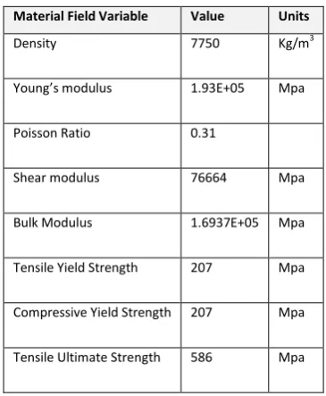
SPECIFICATION OF THE GEARMaterial Field Variable Value Units
Density 7750 Kg/m3
Young’s modulus 1.93E+05 Mpa
Poisson Ratio 0.31
Shear modulus 76664 Mpa
Bulk Modulus 1.6937E+05 Mpa
Tensile Yield Strength 207 Mpa
Compressive Yield Strength 207 Mpa
Tensile Ultimate Strength 586 Mpa Table. 3.1: Specifications of Gear.
http: // www.ijrtsm.com© International Journal of Recent Technology Science & Management 3
ISSN : 2455-9679
[Gauri Shankar et al. , 3(10), Oct 2018 Impact Factor : 2.865
Material Field Variable Value Units
Density 2770 Kg/m3
Young’s modulus 7.1E+10 Mpa
Poisson Ratio 0.33
Shear modulus 2.6692E+04 MPa
Bulk Modulus 6.9608E+04 MPa
Tensile Yield Strength 280 Mpa
Compressive Yield Strength 280 Mpa
Tensile Ultimate Strength 310 Mpa
V.
THEORETICAL
STRESS
CALCULATION
Pitch line velocity
V = П DpNp/60 = П x 0.125x 1500/60 = 9.81 m/s
14.5 T YG = 0.124 – 0.684/Tp = 0.124 – 0.684/20 = 0.089
Ordinary cut gears and operating at velocity ratio is up to 12.5m/s Cv = 3/3+v
Cv = 3/3+9.81 = 0.234 Design Tooth load WT = P Cs/v
WT = 15000 x1 /9.81 = 1529.1 N
WT = ϭw.b.pc.y = ϭw.b.П m.y = (ϭo.Cv) b.Пm.y ϭw. = WT / b.Пm.y
ϭw. = 1529.1 / 22x 3.14x 6 x 0.089
ϭw. = 116.5 MPa
Theoretical bending stress of the designed gear = 116.5 Mpa
VI.
BENDING
STRESS
CALCULATION
USING
ANSYS
The gear is first designed in the ANSYS designer workbench. The calculated co-ordinates are plotted and an involute profile is generated. The addendum circle and dedendum circles are drawn and the profile is connected to for the individual gear tooth.
Material Field Variable Value Units
Density 4620 Kg/m3
Young’s modulus 9.6E+10 Mpa
Poisson Ratio 0.36
Shear modulus 3.528E+11 Mpa
Bulk Modulus 1.1429E+11 Mpa
Tensile Yield Strength 930 Mpa
Tensile Ultimate Strength 930 Mpa
Table 4.2 Aluminium Alloy Mechanical properties
http: // www.ijrtsm.com© International Journal of Recent Technology Science & Management 4
ISSN : 2455-9679
[Gauri Shankar et al. , 3(10), Oct 2018 Impact Factor : 2.865
Fig. 6.3 Equivalent Von misses Stress for Structural Steel Fig. 6.4 Total Deformation on Spur gears for Structure steel
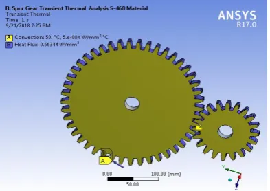
Fig.6.5 Transient Thermal S-460 Boundary Condition Fig.6.6 Temperature S-460 materials
Fig. 6.7 Total heat Flux S-460 Fig.6.8 Equivalent Von misses Stress for Aluminium Alloy
Fig. 6.9 Total Deformation on Spur gears for Aluminium Alloy Fig.6.10 Temperature Aluminium Alloy
http: // www.ijrtsm.com© International Journal of Recent Technology Science & Management 5
ISSN : 2455-9679
[Gauri Shankar et al. , 3(10), Oct 2018 Impact Factor : 2.865
VII.
RESULT
AND
DISCUSSIONS
In this work we find value of vonmisses stresses, Aluminium A y S с S T A y p с y 66.255 MP 66.924MP d 65.553MP d d k S с S A A y d T A y d p с y 0.027328 0.076619 d 0.05645 mm.
T p k S с S A A y d T A y d p с y 127.1 С 126.99 С d 126.97С.
T x k S с S A A y d T A y d p с y 1.1081 w/mm² , 1.1145 w/mm² and 1.1134 w/mm² .
Fig.6.11 Total Heat Flux Aluminium Allo Fig. 6.12 Equivalent Von misses Stress for Titanium Alloy
Fig. 6.13 Total Deformation on Spur gears for Titanium Alloy Fig.6.14 Temperature Aluminium Alloy
http: // www.ijrtsm.com© International Journal of Recent Technology Science & Management 6
ISSN : 2455-9679
[Gauri Shankar et al. , 3(10), Oct 2018 Impact Factor : 2.865
H с d d b с d A A yb с g g d y d y d d g с d b d heat flux value is maximum from other materials.
H с d d b с d A y b с g g d y d y d d g с d b .
Fig.7.1 Frictional Von misses comparison graph for different materials
http: // www.ijrtsm.com© International Journal of Recent Technology Science & Management 7
ISSN : 2455-9679
[Gauri Shankar et al. , 3(10), Oct 2018 Impact Factor : 2.865
Fig.7.3 Temperature comparison graph for different materials
Fig.7.4 Total heatFlux comparison graph for different materials
VII.
CONCLUSION
http: // www.ijrtsm.com© International Journal of Recent Technology Science & Management 8
ISSN : 2455-9679
[Gauri Shankar et al. , 3(10), Oct 2018 Impact Factor : 2.865
REFERENCES
1.
Prashant Kumar Singh , Siddhartha, Akant Kumar Singh An investigation on the thermal and wear behavior of polymer based spur gears, Tribology International 118 (2018) 264–2722.
Wu Jiateng, Yang Yu, Yang Xingkai, Cheng Junsheng, Fault feature analysis of cracked gear based on LOD and analytical-FE method, Mechanical Systems and Signal Processing 98 (2018) 951–9673.
Franulovic, Kristina Markovic, Zeljko Vrcan, Matija Soban, Experimental and analytical investigation of the influence of pitch deviations on the loading capacity of HCR spur gears, Mechanism and Machine Theory 117 (2017) 96–1134.
N k. R g .“E Back-Side contact on mess stiffness of spur gear pair by Finite E M d.”P d E g g 173 ( 2017 ) 1538 – 15435.
Paras Kumar, Harish Hirani, Atul Agrawal Fatigue failure prediction in spur gear pair using AGMA approach, Materials Today: Proceedings 4 (2017) 2470–24776.
Miryam B. Sánchez, Miguel Pleguezuelos, José I. Pedrero, Approximate equations for the meshing stiffness and the load sharing ratio of spur gears including hertzian effects, Mechanism and Machine Theory 109 (2017) 231–2497.
Dattatray B. Vaitkar1a, Prashant N.Ulhe, Experimental Investigation and Finite Element Analysis of Contact Stresses of Spur Gear Used in Automated Lathe Machine, International Journal of Innovative and Emerging Research in Engineering Volume 4,Issue 6, 20178.
Xihui Liang, Hongsheng Zhang, LibinLiu , MingJ.Zuo, The influence of tooth pitting on the mesh stiffness of a pair of external spur gears, Mechanism and MachineTheory106(2016)1–15.9.
Santosh S. Patil, Saravanan Karuppanan, Ivana Atanasovska ,Experimental measurement of strain and stress state at the contacting helical gear pairs, Measurement 82 (2016) 313–32210.
Miriam B. Sánchez, Miguel Pleguezuelos, José I. Pedrero, Calculation of tooth bending strength and surface durability of internal spur gear drives,Mechanism and Machine Theory 95 (2016) 102–11311.
Ankur Saxena, Anand Parey, Manoj Cooksey, Effect of shaft misalignment and friction force on time varying mesh stiffness of spur gear pair, Engineering Failure Analysis 49 (2015) 79–9112.
Putti Srinivasa Rao, Nadipalli Sriraj, Mohammad Farookh, Contact Stress Analysis of Spur Gear for Different Materials using ANSYS and Hertz Equation, International Journal of Modern Studies in Mechanical Engineering (IJMSME) Volume 1, Issue 1,June 2015, PP 45-52