Solid State Bonding of Carbon Material to Copper with Nickel Insert
*1Hidekazu Sueyoshi and Hisayoshi Fukudome
*2Graduate School of Science and Engineering, Kagoshima University, Kagoshima 890-0065, Japan
Carbon material/nickel/copper system was heated under a compressive stress of 13 MPa in a vacuum at 1073 K for different keeping times, and the bending strength of the joint, the microstructure, hardness and carbon concentration near the joining interface were examined. Thermal stress induced in the joint was estimated by a finite element method. In carbon material/copper system solid state bonding is difficult. However, good solid state bonding becomes feasible when nickel is used as an insert metal. Axisymmetric thermoelastic finite element analysis reveals that the maximum tensile thermal stress is induced on the surface of carbon material near the joining interface, and it decreases with increasing nickel thickness. The maximum residual tensile thermal stress in practical joints is less than the maximum tensile thermal stress calculated by finite element method because the thermal stress is released. [doi:10.2320/matertrans.H-MRA2008819]
(Received April 2, 2008; Accepted May 27, 2008; Published July 24, 2008)
Keywords: solid state bonding, carbon material, copper, nickel, insert metal, thermal stress, bending strength
1. Introduction
Carbon materials have excellent electrical conductivity, thermal conductivity, heat resistance, corrosion resistance and tribological properties are, and also are light weight. Thus they are widely used in various fields such as electrical, high temperature, tribological, wear resistant, nuclear fusion reactor and aero-space plane materials. However, hybrid structures in which carbon materials are combined with metallic materials are generally adopted for various devices and machinery because carbon materials are brittle. Hybrid-ization is usually performed by mechanical joining. Brazing is also employed in the manufacture of nuclear fusion reactors.1) On the other hand, soldering and solid state
bonding are utilized on the joining of metal to ceramics such as oxide, nitride and carbide.2) However, few studies have
systematically examined the joining of carbon materials to metals.
The present authors previously reported the solid state bonding of carbon materials to carbon steel, austenitic stainless steel, nickel and nickel-based superalloy.3–9)Copper
has excellent electrical and thermal conductivities, and also is ductile. If the excellent characteristics of both copper and carbon materials are maintained by joining, new prospects can be offered for development of various devices and machinery with high efficiency. However, there are few reports on the solid state bonding of carbon materials to copper. According to copper-carbon phase diagram,10) the
solubility of carbon in copper is very low. This suggests that no diffusion bonding is achieved in copper/carbon material joining system. The present authors reported previously that diffusion bonding is achieved in nickel/carbon material joining system.5,7)Since nickel and copper form a continuous
series of solid solution,11) good diffusion bonding may be
achieved by interdiffusion in copper/nickel joining system. These suggest that solid state bonding of carbon materials to copper is possible by using nickel as an insert material.
In the present study, solid state bonding of carbon material to copper with nickel insert was experimentally examined.
2. Experimental Method
As test materials, a graphite rod (Mechanical Carbon Co, Ltd.) having a purity of 99.9 mass%, a modulus of elasticity of 10 GPa, a Poisson’s ratio of 0.16 and a thermal expansion coefficient of5:94106K1, copper rod (Niraco Co. Ltd.)
having a purity of 99.9 mass%, a modulus of elasticity of 130 GPa, a Poisson’s ratio of 0.34 and a thermal expansion coefficient of1:66105K1, and nickel sheet (Niraco Co. Ltd.) having a purity of 99 mass%, a modulus of elasticity of 209 GPa, a Poisson’s ratio of 0.31 and a thermal expansion coefficient of 1:37105K1 were used. The joining
specimen of carbon material was a column 5 mm in diameter and 31 mm in length, and that of copper was a column 5 mm in diameter and 15 mm in length. The joining surface of the carbon material was finished by grinding using #3000 emery paper followed by dry-buffing, and that of copper was finished by polishing using a 1mm diamond. Nickel as an insert metal was a disk 5 mm in diameter and 0.5 and 1 mm in thickness. The joining surfaces of nickel were finished by polishing using a 1mmdiamond.
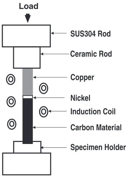
Figure 1 shows a schematic illustration of joining system using RF-induction furnace. The carbon material, nickel and copper were placed in the center of RF-induction coil. Bonding was performed under a compressive stress of 13 MPa in a vacuum (4103Pa) at 1073 K for different
keeping time. The conditions of compressive stress and joining temperature were set on the basis of the results5,7)
which were previously reported by the present authors and proof stress of copper.
The fracture strength of the joint was then measured by the four-point bending test (distance between upper fulcrums: 10 mm, distance between lower fulcrums: 30 mm, crosshead speed: 0.05 mm). The microstructure and element distribu-tion of the longitudinal secdistribu-tion traversing the joining inter-face were examined using an electron probe micro-analyzer (EPMA). The distribution of Vickers hardness (Load: 0.49 N) in nickel was also measured in the direction of depth from the joining interface on the same longitudinal section.
*1This Paper was Originally Published in Japanese in J. Japan. Soc. Heat
Treatment47(2007) 271–276.
*2Graduate Student, Kagoshima University, Present address: Nakayama
Thermal stress induced by cooling from the joining temperature to room temperature was calculated by axisym-metric thermoelastic finite element method (FEM). The general-purpose program I-DEAS was used for this analysis. The joining model was a column of 5 mm in diameter and (30+nickel thickness) mm in length (carbon material: 15 mm, copper: 15 mm, nickel: 0.5 and 1 mm). Concentration of the thermal stress on the surface near the joining interface resulted in fine division of elements near the joining interface. The physical properties of carbon material, copper and nickel were assumed to be constant (the values at room temperature) in this analysis.
3. Results and Discussion
Figure 2 shows the relationship between the bending strength of carbon material/nickel/copper joints and keeping time at 1073 K. The dashed line shows the bending strength of monolithic carbon material. When the keeping time was short (300 s), no bonding was achieved. At keeping time of 600 s, bonding was achieved. However, fracture in bending test occurred at carbon material/nickel interface, resulting in low bending strength. This is because bonding of carbon material to nickel was incomplete. When the keeping time was longer than 1.2 ks, fracture in bending test occurred in carbon material near the joining interface in every case. This suggests that bonding strength at the carbon material/nickel and nickel/copper interfaces is larger than that of carbon material. As shown in Fig. 2, the bending strength of the joint was almost constant when good bonding of carbon material
to nickel was achieved. However, the bending strength of the joint was lower than that of monolithic carbon material and the magnitude of reduction decreased with increasing nickel thickness, suggesting that thermal stress influences the bending strength of the joint.
Figure 3 shows Vickers hardness and carbon concentration of nickel-longitudinal section of the joint bonded by heating at 1073 k for 1.2 ks. The hardness of the area from the joining interface to a depth of about 200mmwas higher than that of the matrix and also the hardness increased near the joining interface. Carbon concentration was obtained by solving Fick’s second law12) under the boundary conditions of an
initial carbon content of 0 mass% and the carbon concen-tration at the joining interface being equal to the solubility of carbon in nickel (0.12 mass%).13,14)The values used for frequency factor and activation energy for carbon diffusion in nickel were D0¼1:3105m2/s, Q¼144kJ/mol,
respectively.15)As shown in Fig. 3, the change in hardness corresponded to that in carbon concentration, suggesting that
SUS304 Rod
Ceramic Rod
Copper
Carbon Material
Induction Coil
Specimen Holder
Nickel
Load
Fig. 1 Schematic illustration of joining system using RF-induction furnace.
0 10 20 30 40 50
0
Keeping Time, t / s
Bending Strength,
σb
/ MP
a
1.0 mm Ni 0.5 mm Ni
Monolithic Carbon Material
3000 2400
1800 1200
600
Fig. 2 Relationship between the bending strength of carbon material/ nickel/copper joints and keeping time at 1073 K.
Vic
ker
s Har
dness,
Hv
Carbon Concentration
0 20 40 60 80 100 120 140 160 180 200
0
0.00 0.02 0.04 0.06 0.08 0.10 0.12 0.14 0.16 0.18 0.20
Hv
1000 800 600 400 200
Carbon Concentration,
C
(mass%)
Distance from Interface, z /µm
[image:2.595.59.275.72.378.2] [image:2.595.306.546.73.258.2] [image:2.595.308.549.313.499.2]the increase in hardness near the joining interface is due to solution hardening by carbon atoms. Thus good diffusion bonding of carbon material to nickel is achieved by carbon diffusion into nickel.
[image:3.595.49.290.72.260.2]Figure 4 shows a secondary electron (SE) image near nickel/copper interface of the longitudinal section of the joint bonded by heating at 1073 K for 1.2 ks. The left-hand side is nickel, the right-hand side is copper and the center is the position of joining interface. As shown in Fig. 4, no joining interface and no intermetallic compounds were observed. This is because nickel and copper form a continuous series of solid solution.11)
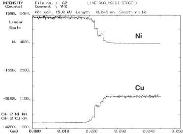
Figure 5 shows line analysis near nickel/copper interface of the longitudinal section of the joint bonded by heating at 1073 K for 1.2 ks. Interdiffusion between nickel and copper having a diffusion distance of about 10mm was confirmed from the changes in nickel and copper profiles. Disappear-ance of joining interface shown in Fig. 4 is due to this interdiffusion, resulting in strong bonding of nickel to copper. As mentioned above, the bending strength of the joint was lower than that of monolithic carbon material because of induced thermal stress. Thermal stress induced by cooling from joining temperature (1073 K) to room temperature (293 K) was examined by FEM. Figure 6 shows thermal stress distribution on the surface of carbon material/copper joint. Tensile thermal stress was induced in carbon material, whereas compressive thermal stress was induced in copper. This is because the thermal expansion coefficient of carbon material is smaller than that of copper. The tensile thermal stress in carbon material reaches the largest value at a distance about 0.5 mm from the joining interface, and thereafter decreasing with increasing distance from the joining interface.
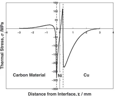
Figure 7 shows thermal stress distribution on the surface of carbon material/0.5 mm thickness nickel/copper joint. Ther-mal stress distribution in the joint was similar to that of carbon material/copper joint (Fig. 6). Nickel has a thermal expansion coefficient halfway between carbon material and copper, resulting in the induction of compressive thermal stress at carbon material side in nickel and tensile thermal stress at copper side in nickel. In Fig. 7 the maximum tensile stress in carbon material is smaller than that of carbon material/copper joint. This is because the thermal expansion coefficient of nickel is smaller than that of copper, while the modulus of elasticity of nickel is larger than that of copper.
Fig. 4 SE image near nickel/copper interface of the longitudinal section of the carbon material/nickel/copper joint bonded by heating 1073 K for 1.2 ks.
Ni
Cu
[image:3.595.110.482.486.760.2]As shown in Fig. 7, the maximum tensile thermal stress in carbon material is located about 0.5mm from the joining interface. In the bending test, the position of fracture corresponded to that of maximum tensile thermal stress, suggesting that the bending strength of the joint is closely related to thermal stress.
Figure 8 shows thermal stress distribution on the surface of carbon material/1.0 mm thickness nickel/copper joint. The thermal stress distribution was similar to that in Fig. 7. However, the value of maximum tensile thermal stress in carbon material is smaller than that of carbon material/ 0.5mmthickness nickel/copper joint (Fig. 7), resulting in the increase in bending strength as shown in Fig. 2.
Figure 9 shows the relationship between the maximum tensile thermal stress on the surface of carbon material and the thickness of nickel. The difference between the bending strength of monolithic carbon material and that of the joint is regarded as the residual thermal stress on the surface of carbon material in the joint. These values estimated from bending strength were also shown in Fig. 9. The maximum tensile thermal stress calculated by FEM decreased with increasing nickel thickness up to the thickness of 2 mm
and thereafter tended to be constant when the thickness of nickel was larger than 2 mm. This suggests that the joint with remarkably thick nickel is regarded as carbon material/nickel joint rather than carbon material/nickel/ copper joint. Thus, it is found that the limitation of nickel thickness as an insert metal is about 2 mm. As shown in Fig. 9, the residual thermal stress was very small compared with the maximum tensile thermal stress calculated by FEM. Because temperature dependence of the thermal expansion coefficient of nickel is similar to that of copper, the effect of temperature dependence of the thermal expansion coefficient on calculated maximum tensile thermal stress may be small. These results suggest that thermal stress is considerably released by some action during bonding process. Point defects in carbon material near the joining interface increase with the increase in the amount of carbon atoms which diffuse into nickel. The increase in the concentration of the point defects allows carbon material to be deformed easily, resulting in relaxation of thermal stress.
–350 –300 –200 –150 –100 –50 0 50 100 150 –4
Distance from Interface, z / mm
Thermal Stress,
σ
/MP
a
Carbon Material Ni
4 3 2 1 0 –1 –2 –3 Cu –250
Fig. 7 Thermal stress distribution on the surface of carbon material/ 0.5 mm thickness nickel/copper joint.
–450 –400 –350 –300 –250 –150 –100 –50 –200 0 50 –4
Distance from Interface, z/ mm
Thermal Stress,
/MP
a
σ
Carbon Material Cu
4 3 2 1 0 –1 –2 –3
Fig. 6 Thermal stress distribution on the surface of carbon material/copper joint.
Carbon Material Cu
–400 –300 –200 –100 0 100 200 300
–4 –3 –2 –1
Distance from Interface, z/mm
Thermal Stress, /MP a σ Ni 4 3 2 1 0
Fig. 8 Thermal stress distribution on the surface of carbon material/ 1.0 mm thickness nickel/copper joint.
0 5 10 15 20
0 1 4
25
Thickness of Ni, TN/mm
σMAX
/ MP
a
Calculated by FEM
Estimated from Bending Strength
3 2
[image:4.595.51.290.73.221.2] [image:4.595.289.545.74.252.2] [image:4.595.50.291.273.475.2] [image:4.595.308.548.309.495.2]4. Conclusions
Carbon material/nickel/copper system was heated under a compressive stress of 13 MPa in a vacuum at 1073 K for different keeping times, and the bending strength of the joint, the microstructure, hardness and carbon concentration near the joining interface were examined. Thermal stress induced in the joint was estimated by a finite element method. The conclusions obtained are as follows:
(1) In carbon material/copper system solid state bonding is difficult. However, good solid state bonding becomes feasible when nickel is used as an insert metal. (2) Axisymmetric thermoelastic finite element analysis
reveal that the tensile thermal stress is induced on the surface of carbon material near the joining interface, the maximum tensile thermal stress is located about 0.5mm
from the joining interface, and it decreases with increasing nickel thickness.
(3) In practical carbon material/nickel/copper joints, the tensile thermal stress induced in carbon material is considerably released.
REFERENCES
1) New Comprehensive Bibliography on Joining Technology, Ed. by K. Nishiguchi, (Sangyou Gijutsu Service Center, 1994) p. 1075. 2) Data Handbook on Joining Technology, Vol. II, Ceramic System, Ed.
by M. Douyama and O. Takai, (Science Forum, 1992) p. 50. 3) H. Sueyoshi, N. Fukuda and T. Nishida: Mater. Trans., JIM39(1998)
1084–1092.
4) H. Sueyoshi and T. Nishida: Mater. Trans., JIM41(2000) 414–419. 5) H. Sueyoshi and T. Nishida: Mater. Trans.42(2001) 163–170. 6) H. Sueyoshi and T. Nishida: Mater. Trans.42(2001) 1945–1951. 7) H. Sueyoshi and T. Nishida: Mater. Trans.42(2001) 2559–2566. 8) T. Nishida and H. Sueyoshi: Mater. Trans.44(2003) 148–154. 9) T. Nishida and H. Sueyoshi: Mater. Trans.47(2006) 399–404. 10) ASM Handbook Vol. 3 Alloy Phase Diagrams, Ed. by H. Baker, (ASM
International, 1992) p. 2-100.
11) ASM Handbook Vol. 3 Alloy Phase Diagrams, Ed. by H. Baker, (ASM International, 1992) p. 2-173.
12) P. G. Shewmon:Diffusion in Solid, (McGraw-Hill, 1963) p. 6. 13) ASM Handbook Vol. 3 Alloy Phase Diagrams, Ed. by H. Baker, (ASM
International, 1992) p. 2-112.
14) Constitution of Binary Alloys, Ed. by M. Hansen and K. Anderko, (McGraw-Hill, 1958) p. 374.