ORIGINAL RESEARCH
INTERVENTIONAL
High-Resolution C-Arm CT and Metal Artifact Reduction
Software: A Novel Imaging Modality for Analyzing Aneurysms
Treated with Stent-Assisted Coil Embolization
X I. Yuki, Y. Kambayashi, A. Ikemura, Y. Abe, XI. Kan, A. Mohamed, XC. Dahmani, XT. Suzuki, XT. Ishibashi, XH. Takao, M. Urashima, and XY. Murayama
ABSTRACT
BACKGROUND AND PURPOSE: Combination of high-resolution C-arm CT and novel metal artifact reduction software may contribute to the assessment of aneurysms treated with stent-assisted coil embolization. This study aimed to evaluate the efficacy of a novel Metal Artifact Reduction prototype software combined with the currently available high spatial-resolution C-arm CT prototype implementation by using an experimental aneurysm model treated with stent-assisted coil embolization.
MATERIALS AND METHODS: Eight experimental aneurysms were created in 6 swine. Coil embolization of each aneurysm was performed by using a stent-assisted technique. High-resolution C-arm CT with intra-arterial contrast injection was performed immediately after the treatment. The obtained images were processed with Metal Artifact Reduction. Five neurointerventional specialists reviewed the image quality before and after Metal Artifact Reduction. Observational and quantitative analyses (via image analysis software) were performed.
RESULTS:Every aneurysm was successfully created and treated with stent-assisted coil embolization. Before Metal Artifact Reduction, coil loops protruding through the stent lumen were not visualized due to the prominent metal artifacts produced by the coils. These became visible after Metal Artifact Reduction processing. Contrast filling in the residual aneurysm was also visualized after Metal Artifact Reduction in every aneurysm. Both the observational (P⬍.0001) and quantitative (P⬍.001) analyses showed significant reduction of the metal artifacts after application of the Metal Artifact Reduction prototype software.
CONCLUSIONS: The combination of high-resolution C-arm CT and Metal Artifact Reduction enables differentiation of the coil mass, stent, and contrast material on the same image by significantly reducing the metal artifacts produced by the platinum coils. This novel image technique may improve the assessment of aneurysms treated with stent-assisted coil embolization.
ABBREVIATIONS:MAR⫽Metal Artifact Reduction; HR⫽high-resolution
S
tent-assisted coil embolization has recently become a com-mon treatment strategy for wide-neck aneurysms.1-4 How-ever, poor visibility of the deployed stent during the procedure is considered a limitation because digital subtraction angiography does not allow the visualization of many intracranial stents. Ovalization or kinking of the deployed stent in the parent artery is another limitation.5-8This phenomenon, also called“inappropri-ate stent apposition,” can hinder the growth of neointimal cover-age on the stent.9Consequently, treated patients are required to undergo a prolonged postprocedural antiplatelet therapy.
Recent reports show that C-arm CT with contrast has superior spatial resolution compared with conventional CT and allows the visualization of both the deployed stent and the contrast mate-rial.8,10-12However, once coil embolization is completed, prom-inent metal artifacts produced by the platinum coils degrade the image quality in the region adjacent to the coil mass, making it extremely difficult to evaluate the minuscule structures around the coil mass.
A new prototype software, Metal Artifact Reduction (MAR; Siemens, Erlangen, Germany), dramatically reduces the metal artifacts in C-arm CT imaging by using a novel image-reconstruc-tion algorithm.13,14Combined with currently available high spa-tial-resolution C-arm CT prototype implementation, the soft-ware enables visualization of meticulous structures around highly attenuated materials like platinum coils.
Received January 27, 2015; accepted after revision June 17.
From the Department of Neurosurgery, The Jikei University School of Medicine, Tokyo, Japan.
This work was supported by a Siemens Research Grant.
Part of this paper was previously presented at: International Stroke Conference, February 12–14, 2014; San Diego, California.
Please address correspondence to Ichiro Yuki, MD, Department of Neurosurgery, The Jikei University School of Medicine, 105-8461 Nishi-Shinbashi 3-25-8, Minato-ku, Tokyo, Japan; e-mail: [email protected]; @ichirodyna
Indicates open access to non-subscribers at www.ajnr.org
To evaluate the efficacy of MAR, we treated experimental an-eurysms with coil embolization by using a stent-assisted tech-nique. Images obtained by using the high-resolution (HR) C-arm CT were processed with MAR. The images before and after MAR processing were compared, and an observational and quantitative analysis was performed.
MATERIALS AND METHODS
Image AcquisitionThe images were acquired by using a floor-mounted neuroangio-graphic unit equipped with 1920⫻2480 cesium iodide–amor-phous silicon flat panel detectors covering an area of approxi-mately 30⫻40 cm (Artis zee floor; Siemens). The motorized frontal C-arm, typically used for 3D rotational angiography or soft-tissue-optimized C-arm CT, was used to acquire 496 projection images over a 200° arc (rotation time, 20 seconds) at 80 kV(peak) and a total of 260 mAs. The radiation dose for 1 rotational acquisition ranged from 187 to 233 mGy, depending on the position of the scanned animal and the actual conditions of the scan. The focal spot and source-to-detector distances were 0.3 and 1200 mm, respectively. The objects of interest were positioned at the center of rotation, 750 mm from the source.
To maximize spatial resolution, we used a nonbinned mode instead of the 2⫻2 pixel binning typically used to provide supe-rior contrast resolution for soft-tissue imaging of the C-arm CT. The source projection frames were acquired in a 512⫻512 matrix covering an FOV of 22 cm diagonally. The rotational datasets were processed with a “normal” (or “sharp”) kernel type, and each acquisition was reconstructed to 2 volume datasets with a 512⫻512 matrix and an isotropic voxel size ranging from 0.06 to 0.08 mm (corresponding to approximately 30⫻30 mm and 40⫻ 40 mm FOVs, respectively). The first of these 2 volumes was un-corrected and showed significant metal artifacts, whereas the sec-ond featured a metal artifacts correction obtained through the application of the MAR prototype software.
In Vitro Evaluation of the Intracranial Stent by High-Resolution C-Arm CT
To compare the image quality produced by conventional C-arm CT with that of the novel HR C-arm CT, 2 Neuroform stents (4.5⫻20 mm) (Stryker Neurovascular, Kalamazoo, Michigan) were deployed in a silicone vessel model that simulated a bifurca-tion of a 4-mm vessel. This was scanned by 2 different types of C-arm CT modalities: one with a conventional C-arm CT (Axiom Artis dBA; Siemens), and the other with the high-resolution C-arm CT (Artis zee floor). The 3D volume-rendering images were created by using a Syngo Workplace (Siemens). The obtained 2 images were compared.
Creation of Swine Sidewall Aneurysms followed by Stent-Assisted Coil Embolization
All of the animal experiments were approved by The Jikei Univer-sity Animal Research Committee. In every treated swine, a side-wall aneurysm was surgically created on each common carotid artery by using a venous graft. Eight experimental aneurysms were created in 6 swine. The aneurysms were designed to be uniformly approximately 6 – 8 mm in size. To reproduce a wide-neck
aneu-rysm, we adjusted the size of the neck to 4 –5 mm in length. The detailed surgical technique was described elsewhere.15
After the creation of an aneurysm on each side of the common carotid artery, a 6F short sheath was placed on the right femoral artery. Using the sheath, we advanced a 6F guiding catheter to the ipsilateral common carotid artery and DSA was performed to confirm sufficient contrast filling in the aneurysm. Via the guid-ing catheter, a microcatheter, Excelsior 1018 (Stryker), was placed in the aneurysm. An intracranial stent was then deployed across the neck of the aneurysm via another microcatheter, Excelsior XT-27 (Stryker).
Three aneurysms were treated with Neuroform EZ stents (Stryker Neurovascular). One aneurysm was treated with an En-terprise stent (Codman & Shurtleff, Raynham, Massachusetts), and 4 were treated with a prototype stent with a closed-cell design (4⫻20 mm). Using a jailing technique, we deployed 3 coils of different sizes into the aneurysms, including Matrix2(Stryker),
10⫻30 cm; GDC-10 (Stryker), 6⫻10 cm; and GDC-10, 3⫻6 cm. Every aneurysm was intentionally left underpacked so that the resid-ual aneurysm could be evaluated postoperatively. In 2 aneurysms, part of the deployed coil was intentionally herniated through the stent lumen, to simulate a situation sometimes encountered in the clinical setting.
HR C-Arm CT with Contrast (Intra-Arterial Injection Protocol) followed by MAR Processing
Using the guiding catheter placed at the proximal common ca-rotid artery, we injected 20% diluted contrast material with an injection speed of 2 mL/s for 22 seconds. The image-acquisition-delay time was set at 2 seconds. The raw data of the HR C-arm CT was sent to a postprocessing workstation syngo XWP (Siemens), and the 3D reconstruction of the obtained images was performed by using syngo InSpace software (Siemens). These were saved as the original preprocessing images.
The raw data of the obtained images were then recon-structed by using the MAR prototype software. The post-MAR images were further processed by using an image-processing application, Aquarius iNtuition, Version 4.4.7.108.0 (TeraRe-con, San Mateo, California) to build modified volume-render-ing images.
Observer Analysis of the Efficacy of MAR Image Processing
Quantitative Analysis of the Efficacy of MAR and HR C-Arm CT
Quantitative analysis of the efficacy of MAR was also performed by measuring the volume of the streak artifacts produced by the coil material. First, by using 3D reconstruction data of a post-MAR image, we created the baseline coil image by setting the window level that provided the best visualization of the coil mass alone. The volume of the metal obtained from this baseline coil image was defined as “baseline metal volume.” This volume was calculated by using a free open-source software package for image analysis and scientific visualization (3D Slicer, Version 4.3; http://www.slicer.org).
Second, the window level of the post-MAR image was adjusted for optimal visualization of the parent artery, stent, and coil mass. The same window level was also applied to the pre-MAR image. This adjusted viewing was defined as “optimized visualization” pre- and post-MAR. The volume of the object observed in each of these optimized visualizations (ie, pre- and post-MAR) was then calculated by using the same software, 3D Slicer.
Last, the baseline metal volume was subtracted from each of the pre- and post-MAR volumes, and the differences between the obtained volumes (pre-MAR in optimized visualization minus baseline metal volume and post-MAR in optimized visualization minus baseline metal volume) were considered as the amount of streak artifacts produced by the coil mass.
The average volume of streak artifacts in the pre-MAR images was compared with the average volume calculated in the post-MAR image. Statistical analysis was performed by the Studentt test. Significance was set at a 2-tailedP⫽.05.
RESULTS
In Vitro Evaluation of the Intracranial Stent by High-Resolution C-Arm CT
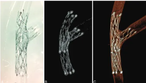
A photograph of the Neuroform stents deployed in a silicone vessel model by using the stent-in-stent technique is shown in
Fig 1A. The image obtained by using the conventional C-arm CT (Fig 1B) shows the 2 Neuroform stents (4⫻20 mm) placed in the silicone vessel model with limited visualization of de-tailed structures (eg, stent struts). The image obtained by the HR C-arm CT (Fig 1C) demonstrates the meticulous struc-tures of the deployed stents, including the small gaps between the struts, which were the structural features of the open-cell-design stent.
HR C-Arm CT with Contrast Injection followed by MAR All 8 aneurysms in the 6 swine were successfully created and were treated by coil embolization by using the stent-assisted technique. Embolization was stopped before complete occlusion of the an-eurysm so that the residual anan-eurysm could be evaluated by post-treatment angiography.
In all aneurysms, thin-section MIP images of the HR C-arm CT obtained immediately after the procedure revealed metal ar-tifacts produced by the coil mass. In the pre-MAR image, the image quality near the coil mass was degraded due to the metal artifacts, and differentiating the coils from the stent was difficult. The thin-section MIP images of the post-MAR image showed reduction of the metal artifacts (Fig 2A). The microcatheter placed in the aneurysm via the stent struts became visible after MAR (Fig 2B).
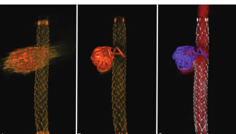
[image:3.594.54.532.46.317.2]The volume-rendering images of an aneurysm treated with coil embolization by using an Enterprise stent are shown inFig 3. Again, the visibility of the structures around the coil mass in the pre-MAR
image (Fig 3A) was improved after MAR processing (Fig 3B). The post-MAR image was further processed by using an image-processing application, Aquarius iNtuition, Version 4.4.7.108.0, to build special FIG 2. Thin-section MIP images of the aneurysms treated with stent-assisted coil embolization.A, Comparison of the pre- (left) and post-MAR (right) images of an aneurysm treated with a combination of bare platinum coils and a Neuroform stent (4⫻20 mm) reveals improved visibility of the stent structures near the coil mass after MAR processing.B, Another aneurysm that was treated with coil embolization by using a Neuroform stent. Note the improved visibility of the microcatheter inserted in the aneurysm and contrast filling in the aneurysm after the MAR processing (right).
[image:4.594.53.533.48.317.2] [image:4.594.56.532.366.637.2]volume-rendering images (Fig 3C). The coil mass (purple) is clearly differentiated from the stent (silver), and the coil loop protruding into the stent lumen is clearly visualized.
Observer Analysis of the Efficacy of MAR and HR C-Arm CT
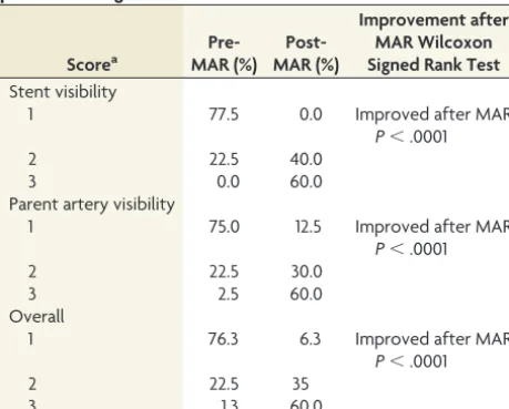
The results of the observer study are summarized in theTable. First, the stent visibility near the orifice of the coil mass was evaluated by using the pooled data analysis. In the pre-MAR images, 77.5% of the samples rated had a score of 1 (insufficient for the diagnosis), while
22.5% had a score of 2 (sufficient for the diagnosis). No sample was rated 3 (excellent). In the post-MAR images, 0%, 40%, and 60% of the samples rated had scores of 1, 2, and 3, respectively.
Similarly, the visibility of the parent artery near the coil mass was evaluated. In the pre-MAR images, 75% of the samples rated had a score of 1, 22.5% had 2, and 2.5% had 3. In the post-MAR images, 12.5%, 30%, and 60% of the samples had scores of 1, 2, and 3, respectively.
Overall, in the pre-MAR images, 76.3% of the samples had a score of 1, 22.5% had 2, and 1.3% had 3. In the post-MAR images, 6.3% of the samples had a score of 1, 35% had 2, and 60% had 3. By the Wilcoxon matched pairs signed rank test, for all cate-gories, the pooled scores given by the observers to the C-arm CT images before MAR were significantly improved after the images were processed with MAR (P⬍.0001).
Quantitative Analysis of the Efficacy of MAR and HR C-Arm CT
The baseline coil image is shown inFig 4A. Using the workstation syngo Workplace, we adjusted the width and level of the window, the slab thickness, and the position of the images in the post-MAR image (Fig 4B). The same parameters were applied to the pre-MAR image (Fig 4C). The baseline coil volume was subtracted from both the pre- and post-MAR images, and the difference was defined as the “streak artifacts.”
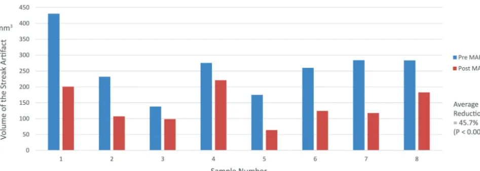
The volume of streak artifacts in the pre-MAR images was compared with that in the post-MAR images (Fig 5). In all 8 an-eurysms, the volume of streak artifacts calculated in the pre-MAR images was significantly reduced in the post-MAR images. The
FIG 4.Quantitative measurement of the streak artifacts.A, Using the 3D reconstruction data of a post-MAR image, we calculated the baseline metal volume by setting the window level that provides the best visualization of the high-attenuation metal component.B, The window level of the post-MAR image is adjusted for the optimal visualization of the parent artery, stent, and coil mass.C, The same window level is applied to the pre-MAR image. The volume of the streak artifacts is determined by the difference of the volume of the pre-MAR image and the volume of post-MAR image. The volume of each image is calculated by using the image analysis software 3D Slicer.
Results of the observer study rating the visibility of pre- and post-MAR images
Scorea
Pre-MAR (%)
Post-MAR (%)
Improvement after MAR Wilcoxon Signed Rank Test Stent visibility
1 77.5 0.0 Improved after MAR
P⬍.0001
2 22.5 40.0
3 0.0 60.0
Parent artery visibility
1 75.0 12.5 Improved after MAR
P⬍.0001
2 22.5 30.0
3 2.5 60.0
Overall
1 76.3 6.3 Improved after MAR
P⬍.0001
2 22.5 35
3 1.3 60.0
[image:5.594.54.284.194.379.2]greatest volume reduction was observed in sample 5, in which the volume of streak artifacts decreased from 174.6 to 63.9 mm3,
yielding a 63.4% artifacts reduction. The lowest volume reduction was seen in sample 4, from 275.1 to 220.8 mm3, yielding an
arti-facts reduction of 19.8%. The average artiarti-facts reduction for all samples was 45.7%. By the Studentttest, there was a statistically significant difference between the examined datasets (P ⫽ .00034).
DISCUSSION
Application of Metal Artifact Reduction Software on Currently Available High-Resolution C-Arm CT Images van der Bom et al14reported the efficacy of a metal artifacts cor-rection software on high-resolution C-arm CT images of patients treated with stent-assisted coil embolization. They concluded that the MAR software they used was not capable of fully removing artifacts caused by the implants, even though the image quality of the C-arm CT data was drastically improved after MAR.
The algorithm of the MAR used in the aforementioned study is based on the procedure proposed by Prell et al,13whereas the algorithm used in the present work is a modified and extended implementation of the procedure.16 The main difference is a higher dimension of the matrix used for the reconstruction of the C-arm CT volume (5123compared with 2563), resulting in a
po-tentially higher resolution of the obtained images with relatively smaller voxel sizes for the same FOV. Compared with the cur-rently available normal-resolution C-arm CT images, the quality of the postprocessing images was further improved, allowing bet-ter differentiation among the stent, coils, and contrast dye.
Results of the observational analysis revealed significant improvement in the visibility of the meticulous structures after MAR, which was probably due to the prominent reduction in streak artifacts, as shown in the results of the quantitative anal-ysis. Moreover, the high spatial resolution may have contrib-uted to the improved visibility of the minuscule structures after MAR.
Limitations of the Study
The swine aneurysm model used in this study simulates the sim-ilar size (of the aneurysm and parent artery) and simsim-ilar biofluid mechanical parameters (ie, cardiac output and blood viscosity) observed in human aneurysms. However, the parent arteries in human aneurysms are normally more tortuous and are sur-rounded by a skull. Whether the quality of the images presented in this study can be reproduced in the clinical setting is uncertain.
The effectiveness of the metal artifact reduction can be influ-enced by the volume and attenuation of the high-attenuating ma-terial adjacent to the target vessel. If the stent was surrounded by high-attenuating materials, visualization of the stent will become more challenging. The aneurysm model used in this study was a wide-neck aneurysm, though it does not necessarily represent an extremely wide-neck/fusiform aneurysm. Further study investi-gating the effectiveness of the MAR in such aneurysms treated with stent-assisted coiling should be conducted.
The quantitative analysis of the metal artifacts focuses on the measurement of the streak artifacts, the high-attenuation radiat-ing artifacts from the coil material that are components of several different types of artifacts, including noise, beam-hardening, par-tial volume effect, and scatter. Because the streak artifacts are only 1 component of such complex phenomena, establishing a mea-surement method for the true metal artifacts in reconstructed image data is essential. Notably, the calculated streak artifacts in this study not only include the true artifacts arising from the coil but also the following: 1) part of the stent in the considered vol-ume of interest, 2) the contrast medium in the parent artery con-fined in that same VOI, and 3) artifacts related to other high-attenuation objects (eg, vertebral bones in the VOI).
[image:6.594.58.532.78.247.2]tained from the sequence is essential for the decision-making in the course of treatment. However, it is still crucial to minimize the radiation dose by collimating the ROI as much as possible.
Future Applications
When an extremely wide-neck aneurysm or a fusiform aneurysm is treated with a stent-assisted technique, separating the coil mass from the parent artery in the DSA images often becomes difficult. Intraoperative use of the C-arm CT with MAR may allow distin-guishing the stent, parent artery, and coils. This distinction may contribute to the prevention of technical complications during the procedure.
Second, to date, most patients undergo prolonged antiplatelet therapy after stent-assisted coil embolization due to the concern of a thromboembolic event related to the deployed stent. In fact, in the field of cardiovascular intervention, studies have shown that inappropriate stent apposition causes delay in neointimal coverage, which can lead to the increased risk of a thromboem-bolic event.9
Intra-arterial sonography or intravascular optical coherence tomography is the imaging modality mainly used for the evalua-tion of post-coronary stent placement. None of these modalities, however, are currently applicable to the intracranial artery, which is extremely tortuous and vulnerable compared with the coronary artery.
A combination of HR C-arm CT and MAR may contribute to the risk assessment of thromboembolic events related to the stent-assisted coil embolization by providing information about the postoperative stent apposition in the treated artery.
CONCLUSIONS
The combination of currently available high spatial-resolution C-arm CT with a prototype implementation of MAR enables the differentiation of the coil mass, stent, and contrast material by significantly reducing the metal artifacts produced by the plati-num coils. This novel image technique allows improved visualiza-tion of meticulous structures around the coil mass and may con-tribute to the evaluation of aneurysms treated with stent-assisted coil embolization.
Disclosures: Ichiro Yuki—RELATED:Grant: Siemens*;Support for Travel to Meetings for the Study or Other Purposes: Siemens;Provision of Writing Assistance, Medi-cines, Equipment, or Administrative Support: Stryker provided stents used in the experiment;UNRELATED:Patents (planned, pending or issued): 1) UC Case No. 2010-085-one (Method and Apparatus for a Surface-Modified Coil Material for Treatment of Brain Aneurysm); 2) UC Case No. 2009-668-one (Dual Rotational Stent Apparatus); 3) UC Case No. 2011-135–1; SSD No. 105837.00023 (Bioactive Spiral Coil Coating); Trav-el/Accommodations/Meeting Expenses Unrelated to Activities Listed: Siemens (for attending an international meeting). Ashraf Mohamed—UNRELATED:Employment: Siemens (full-time);Stock/Stock Options: Siemens ($30,000). Toshihiro Ishibashi—
RELATED: Stryker Japan,* Siemens*;Consulting Fee or Honorarium: Stryker Japan;
UNRELATED:Consultancy: Stryker Japan;Grants/Grants Pending: Stryker Japan,* NTT DOCOMO,* Siemens.* Yuichi Murayama—RELATED:Grant: Siemens*;Support for Travel to Meetings for the Study or Other Purposes: Siemens;UNRELATED:
Grants/Grants Pending: Siemens*;Payment for Lectures (including service on Speakers Bureaus): Siemens. *Money paid to the institution.
REFERENCES
1. Chalouhi N, Jabbour P, Singhal S, et al.Stent-assisted coiling of intracranial aneurysms: predictors of complications, recanaliza-tion, and outcome in 508 cases.Stroke2013;44:1348 –53CrossRef Medline
2. Fiorella D, Albuquerque FC, Deshmukh VR, et al.Usefulness of the Neuroform stent for the treatment of cerebral aneurysms: results at initial (3– 6-mo) follow-up.Neurosurgery2005;56:1191–201; discus-sion 1201– 02CrossRef Medline
3. Geyik S, Yavuz K, Yurttutan N, et al.Stent-assisted coiling in endo-vascular treatment of 500 consecutive cerebral aneurysms with long-term follow-up. AJNR Am J Neuroradiol 2013;34:2157– 62
CrossRef Medline
4. Wakhloo AK, Linfante I, Silva CF, et al.Closed-cell stent for coil embolization of intracranial aneurysms: clinical and angiographic results.AJNR Am J Neuroradiol2012;33:1651–56CrossRef Medline
5. Tsuruta W, Matsumaru Y, Hamada Y, et al.Analysis of closed-cell intracranial stent characteristics using cone-beam computed to-mography with contrast material.Neurol Med Chir (Tokyo)2013;53: 403– 08CrossRef Medline
6. Heller R, Calnan DR, Lanfranchi M, et al.Incomplete stent apposi-tion in Enterprise stent-mediated coiling of aneurysms: persistence over time and risk of delayed ischemic events.J Neurosurg2013;118: 1014 –22CrossRef Medline
7. Heller RS, Malek AM.Parent vessel size and curvature strongly in-fluence risk of incomplete stent apposition in Enterprise intracra-nial aneurysm stent coiling. AJNR Am J Neuroradiol 2011;32: 1714 –20CrossRef Medline
8. Patel NV, Gounis MJ, Wakhloo AK, et al.Contrast-enhanced angio-graphic cone-beam CT of cerebrovascular stents: experimental op-timization and clinical application.AJNR Am J Neuroradiol2011;32: 137– 44CrossRef Medline
9. Foin N, Gutie´rrez-Chico JL, Nakatani S, et al.Incomplete stent ap-position causes high shear flow disturbances and delay in neointi-mal coverage as a function of strut to wall detachment distance: implications for the management of incomplete stent apposition. Circ Cardiovasc Interv2014;7:180 – 89CrossRef Medline
10. King RM, Chueh JY, van der Bom IM, et al.The effect of intracranial stent implantation on the curvature of the cerebrovasculature. AJNR Am J Neuroradiol2012;33:1657– 62CrossRef Medline
11. Heller RS, Malek AM.Successful detection of embologenic ulceration in a symptomatic non-hemodynamic intracranial stenosis using C-arm cone beam CT.J Neurointerv Surg2013;5:e3CrossRef Medline
12. Struffert T, Lang S, Adamek E, et al.Angiographic C-arm CT visual-ization of the Woven EndoBridge cerebral aneurysm embolvisual-ization device (WEB): first experience in an animal aneurysm model.Clin Neuroradiol2014;24:43– 49CrossRef Medline
13. Prell D, Kalender WA, Kyriakou Y.Development, implementation and evaluation of a dedicated metal artefact reduction method for interventional flat-detector CT. Br J Radiol 2010;83:1052– 62
CrossRef Medline
14. van der Bom IM, Hou SY, Puri AS, et al.Reduction of coil mass artifacts in high-resolution flat detector conebeam CT of cerebral stent-assisted coiling. AJNR Am J Neuroradiol 2013;34:2163–70
CrossRef Medline
15. Murayama Y, Vin˜uela F, Suzuki Y, et al.Ion implantation and protein coating of detachable coils for endovascular treatment of cerebral aneurysms: concepts and preliminary results in swine models. Neurosurgery 1997;40:1233– 43; discussion 1243– 44CrossRef Medline