MICROPROCESSOR-CONTROLLED PERIPHERALS
A thesis
submitted in partial fulfilment of the requirements for the Degree
of
Master of Science in Computer Science in the
University of Canterbury by
C. P. Stott
University of Canterbury
ABSTRACT
The use of the microprocessor to control a computer's peripheral changes the criteria for the interface between the peripheral and computer. An interface is described in which the data handled by the peripheral is stored in the microprocessor's own memory and the minicomputer is provided with the means to access this data through its IO system.
The interface allows up to 16 microprocessor-controlled peripherals to be interfaced in a manner that places few
I would like to express my gratitude to my supervisors, Dr. M.A. Maclean and Mr. R.M. Harrington for their advice,
guidance and criticism during the course of this investigation. In particular, I would like to thank Mr. Harrington for
suggesting the initial problem and making available laboratory facilities and test equipment used during the development
TABLE OF CONTENTS
CHAPTER 1 INTRODUCTION
PAGE 1 3
3
CHAPTER 2 ARCHITECTURE OF IO SYSTEMS 2.1 CPU-PERIPHERAL COMMUNICATION
2.1.1 A SIMPLE APPROACH TO IO 4
2.1.2 POLLING PERIPHERALS 5
2.1.3 INTERRUPTS 6
2.2 PERIPHERAL-MEMORY COMMUNICATION 8 2.2.1 DIRECT MEMORY ACCESS FACILITIES 8
2.2.2 THE IO PROCESSOR 9
2.3 THE PERIPHERAL AS A PROCESSOR 11 CHAPTER 3 THE MICROPROCESSOR AS A PERIPHERAL
CONTROLLER 13
3.1 THE PRESENT FORM OF A COMPUTER-PERIPHERAL
INTERFACE 13
3.2 THE MICROPROCESSOR 15
3.2.1 REPLACING EXISTING HARDWARE WITH
A MICROPROCESSOR 15
3. 2. 2 .EXPLOITING THE MICROPROCESSOR'S
CAPABILITIES 16
3.3 DESIGN AIMS FOR A NEW HARDWARE
INTERFACE 17
3.3.1 EFFICIENCY 17
3.3.2 TRANSFORMATION OF THE HARDWARE
INTERFACE 18
3.3.3 FLEXIBILITY 18
3.3.4 PORTABILITY 19
3.4 MINICOMPUTER IO FACILITIES 19
3.4.1 REGISTER INTERFACES 20
3.4.2 DMA INTERFACES 20
3.5 AN INTERFACE FOR A
MICROPROCESSOR-CONTROLLED PERIPHERAL 21
3.6 THE SUITABILITY OF OTHER BUS SYSTEMS 24 CHAPTER 4 YAC-BUS ARCHITECTURE
4.1 YAC-BUS COMPONENTS 4 .1.1
4 .1. 2 4 .1. 3 4 .1. 4
YAC-BUS
THE MINICOMPUTER INTERFACE THE PERIPHERAL INTERFACE THE INTERRUPT SYSTEM
26 26 26
4.2.1 BUS CONTROL
4. 2. 2 BUS SYNCHRONISATION
CHAPTER 5 YAC-BUS IMPLEMENTATION
34 37 39
5.1 THE PDP-11 INTERFACE 39
5.1.1 UNIBUS BUFFERING AND TIMING 41 5.1.2 YAC-BUS INTERFACE REGISTERS 41
5.1.3 TAC-BUS TIMING 44
5.1.4 UNIBUS INTERRUPT 48
5.2 OTHER MINICOMPUTER INTERFACES 50
5.3 THE 6800 INTERFACE 51
5.3.1 PERIPHERAL CONTROL AND TIMING 53 5.3.2 DUAL-PORTED MEMORY
5.4 USING OTHER MICROPROCESSORS CHAPTER 6 USING YAC-BUS
6.1 SOFTWARE·FOR YAC-BUS 6.1.1 ALLOCATION OF TASKS 6.1.2 THE USER INTERFACE 6.1.3 USER FACILITIES 6.2 YAC-BUS EFFICIENCY 6.3 A MONITOR FOR YAC-BUS
6.3.1 OVERVIEW
6.3.2 THE 6800 MONITOR 6.3.3 THE PDP-11 MONITOR CHAPTER 7
7.1 7.2 BIBLIOGRAPHY APPENDIX A APPENDIX B
COMMENTS AND CONCLUSIONS CONCLUSIONS
FUTURE WORK AND IMPROVEMENTS
6800 MONITOR LISTING PDP-11 MONITOR LISTING
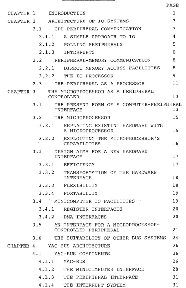
LIST OF FIGURES
FIGURE PAGE
3.1 YAC-Bus 22
4.1 YAC-Bus Configuration 27
4.2 YAC-Bus Memory System 29
4.3 YAC-Bus Interrupt System 32
4.4 YAC-Bus Timing 36
5.1 Block Diagram - Minicomputer
Interface 40
5.2 PDP-11 Interface Registers 42
5.3 Schematic Diagram - Unibus Buffering
and Timing 43
5.4 Schematic Diagram - YAC-Bus Interface
5.5
5.6
5.7
5.8
5.9
5.10
5.11
6.1
Registers 45
Schematic Diagram - YAC-Bus Timing
Timing Diagram - Minicomputer Interface
46
47
Schematic Diagram - Unibus Interrupt 49
Block Diagram - Peripheral' Interface 52
Schematic Diagram - Peripheral Control and Timing
Timing Diagram - Peripheral Interface
Schematic Diagram - Peripheral Dual-Ported Memory
YAC-Bus Access
54
55
56
65
6.2 Accessing YAC-Bus with the PDP-11
CHAPTER l
INTRODUCTION
Peripherals are very important parts of any computer - they are the means by which that computer communicates with its environment. A peripheral may be considered to consist of two parts:
l) the peripheral device - that hardware that interacts directly with the computer's environment; this hardware covers a very diverse range of equipment. It includes such things as
- electromechanical actuators and transducers - storage media such a~ magnetic disks and tapes - display equipment such as lights and cathode ray
tubes
- communication equipment to name but a few.
2) the peripheral controller - that hardware that interfaces the peripheral device with the rest of the computer; this hardware is essentially a collection of digital logic and signa~ level translators.
An important function of the peripheral controller is to provide conversions between the form of information used by the peripheral device and that used by the computer. A common process performed is the conversion between the serial data required by a device and the parallel data handled by the computer. Where the task performed by the peripheral is quite complicated (such as required in the operation of a disk drive or a line printer) , the logic
required within the peripherql controller is quite substantial and is expensive and difficult to design.
If one uses a microprocessor as the basis upon which to design a peripheral controller, the amount of logic
required in the controller can be substantially reduced.
2 .
In this thesis we are not so much interested in the task of the microprocessor as a peripheral controller but more in providing an interface between a computer and a microprocessor-controlled peripheral that makes use of the microprocessor's capabilities. Traditionally, the structure of the peripheral controller has influenced the design of the interface between the peripheral and the computer. Because the controller consisted of hardwired logic, i t meant for
instance that the information transferred across the interface was invariably rigidly formatted. The use of a microprocessor changes the criteria by which a peripheral controller is
designed, especially in respect to the interface.
It is the object of the thesis to examine how the use of a microprocessor may change the design of the interface
between the peripheral and the computer. In the next chapter, chapter 2, the traditional role of the peripheral controller is examirted with regard to the type of information that is required by the computer to control the peripheral and the
actions required of the controller. In chapter 3, we consider the use of a microprocessor as a peripheral-controller.
This leads to a set of design aims for the interface and we discuss in broad details a design that m~ets these aims.
The specifications of YAC-Bus are presented in chapter 4. YAC-Bus is a bus system proposed as a means of interfacing
microprocessor-controlled peripherals to a minicomputer. Chapter 5 details the implementation of interfaces to YAC-Bus for the PDP-11 ~inicomputer and the 6800 microprocessor. We also examine the changes necessary to the interfaces to
allow them to work with different types of minicomputers and microprocessors.
In chapt~r 6, the use of YAC-Bus is explored from a software point of view and there is an example illustrating some of the points raised.
ARCHITECTURE OF IO SYSTEMS
The purpose of this chapter is to examine the
architecture of the Input-Output system of computers, how the designs of two ntinicomputers typify present designs and what considerations influence the design of IO systems in larger computers.
The IO system provides the communication path between a computer's peripherals and the other components of a
computer such as the £entral Erocessing ~nit (CPU) and, in some cases, the memory. In considering these two paths of communication, this chapter examines some aspects of the design and structure of the IO system.
2.1 CPU - PERIPHERAL COMMUNICATION
The CPU - peripheral path is a means of communication in which the CPU plays an active and important role in IO operations. If we consider this path as being the sole means by which peripherals communicate with the rest of the computer then the CPU is responsible for the transferring of data between the peripherals and memory in addition to the task of controlling the peripheral. Thus the implementation of the interface between the peripherals and the CPU is
important on the grounds of efficiency and ease of use by the programmer.
If one or more registers within the peripheral controller are addressable by CPU instructions, data and control
information can be exchanged between the peripheral and the CPU. The design of the Dat~ General Nova minicomputer ~G 78] typifies the traditional approach in the design of this
4.
In contrast, the Digital Equipment PDP-11 [DEC 7 6) range of minicomputers treats the registers within the
peripheral controller as if they were part of memory. Each register is assigned an address within the memory address space so that all instructions that reference memory may
gain access to the registers. Thus no special IO instructions are needed and a large number of registers may be accommodated with few restrictions on the number available to a peripheral. This convenience is achieved through the sacrifice of 4096 words of the memory address space of the PDP-11.
We now consider the control requirements for IO
operations carried out by the CPU and show their implication for CPU and overall computer efficiency.
2.1.1 A SIMPLE APPROACH TO IO
An IO operation involves the transfer of data between peripherals and the rest of the computer. When this involves the CPU, i t could be so arranged that the CPU waits for the peripheral to present data to the interface register on an input operation. In the case of an output operation, the CPU waits until the peripheral is able to accept data for output. In either case, the operation of the CPU is held up until the IO operation has been completed by the peripheral.
An IO operation also involves the issuing of command information by the CPU to the peripheral. For a simple peripheral, this command might imply an input operation to be carried out to fill this register. For peripherals
capable of many functions, the function to be carried out may have to be "stated" by the loading of a special register with the appropriate command.
The main drawback to this type of IO operation is that the CPU is effectively halted for the duration of the operation. Such a system would be useless in a real-time control application where several peripherals are being controlled at the same time. Since a typical CPU is
capable of executing many instructions during the IO operation of a peripheral, the computer could be doing other and perhaps more important tasks. To allow the computer to do this, we must provide the peripheral with some means of indicating
that i t is busy performing an operation and the CPU with
instructions that test this information and allow the computer to take alternative courses of action.
2.1.2 POLLING PERIPHERALS
By providing the CPU with information about the status of its peripherals, more efficient use can be made of the computer. The status information should be sufficient to allow the CPU to determine what the peripheral is currently doing. Since the CPU can determine if a peripheral is busy or finished an operation, by periodically polling the
peripherals for this information, the CPU has the ability to keep the computer running efficiently.
The status information is generally presented in a series of 1-bit flag registers. One flag may indicate if the peripheral is busy performing some IO operation, another may be set when this is finished. Other flags may indicate error conditions or if there is valid data in other registers and so on.
As an example, the PDP-11 (DEC 75) has a status register associated with each of its peripherals. Although the format and contents of this register depend on, the design and function of the peripheral, one finds that one bit is designated the Done bit - when set to 1 by the peripheral i t indicates that the peripheral has completed the current
operation. Other bits indicate the presence of error
6 .
The Nova minicomputer assumes each peripheral has two 1-bit registers known as the Busy and Done registers. These registers can be tested with a special set of
conditional skip instructions. Other status information such as the presence of error conditions depends on the design of the peripheral and is usually provided within one of the 16-bit registers within the peripheral controller.
A particular problem with polling arises with input operations. Keyboard input, for example, can be infrequent and at random intervals but the CPU is obliged to check
if there has been any data input at a rate that has to ensure that all key depressions are registered - the majority of such checks will have nothing_to report.
For a computer with a lot of peripherals, the polling of peripherals can be a considerable task. Polling is
complicated by the presence of fast peripherals which, because of their higher data tr~nsfer rates, have to be checked more frequently than others.
Polling is an attempt at trying to match the orderly execution of programs in a computer with random events
occuring with the operation and use of its peripherals. Its inefficiencies result from the active role of the CPU required in the polling operation. If the peripherals could signal the CPU when they require servicing, the task of the CPU would be reduced considerably.
2.1.3 INTERRUPTS
An interrupt is an event which breaks into the normal operation of the CPU and evokes some response. This event may be the completion of an operation by a peripheral, or when some error condition arises in a peripheral, or i t may
' '
be some event internal to the CPU such as an arithmetic
error (overflow, divide by zero etc) or power failure. The response by the CPU has two parts:
1) the currently running program is halted and
always includes the contents of the program counter and may include the contents of other important registers.
2) automatic transfer of control to a routine to service the interrupt.
An interrupt system frees the CPU from the task of constantly polling peripherals to check their status.
However, there are extra requirements in the design of the computer that are needed in order to cope with interrupts. Beqause there may be many sources of interrupts, the CPU requires information to identify the source to allow for fast servicing. Interrupts can happen at any time, even simultaneously, so there must be a method of determining which interrupts have priority_ over others for servicing by the CPU. The interrupt service routine may itself be
interrupted as i t may be important for very fast peripherals to be able to preempt the servicing of slower ones.
By examining the 'interrupt system of the two mini-computers being cohsidered, i t is possible to see how such issues are resolved. The PDP-11 uses a vectored interrupt system in which the peripheral requesting the interrupt
supplies the CPU with an "interrupt vector", an address from which new values of the program counter and Erogram ~tatus ~ord
(PSW) are loaded, the previous values being pushed onto the stack. The PSW contains important information about the class of peripherals that may interrupt the program currently running. The effect of the vectored interrupt system is to quickly identify the interrupting peripheral as well as to branch to the particular interrupt service routine for the peripheral and change the priority conditions for future
interrupts. The interrupt service routine is responsible for the saving and restoring of the contents of any CPU registers used.
8.
Identification of the peripheral requesting the interrupt must be done by software, an "interrupt acknowledge"
instruction being provided to obtain this information
from the peripheral itself. T·hose classes of peripherals that may interrupt during the servicing of an interrupt are set through the use of the "mask out" instruction.
An enhanced version of the Nova, the Data General Eclipse minicomputer [DG 75] , has a special instruction that does a lot of the work required to service an interrupt. Known as the "vector on interrupting device code"· instruction, i t transfers control to the service routine appropriate to the interrupting peripheral with a series of options. These provide for changing the stack (important when a user program is interrupted) , providing a new interrupt mask and saving important CPU registers such as the accumulators.
2.2 PERIPHERAL - MEMORY COMMUNICATION
Peripherals such as disks and magnetic tapes are capable of quite high data transfer rates once the recording medium has been positioned correctly. To improve the efficiency of such peripherals, i t is usual for the data to be stored in blocks of several hundreds or even thousands of words or characters. IO operations involving these blocks of
information would be particularly wasteful of CPU capacity if carried out in the manner suggested in the previous section. In practice, i t is usual to find that such peripherals have specialised hardware to allow blocks of data to be transferred directly to and from memory once the transfer has been
initiated by instructions from the CPU. The ability to
transfer data directly to memory requires further capabilities on the part of the IO system.
2.2.1 DIRECT MEMORY ACCESS FACILITIES
of the IO system, memory address information is required as well for DMA transfer of data. In minicomputers, this address information is held by -the peripheral together with information as to the amount of data to be transferred.
The exact way in which a DMA is provided depends on the computer architecture. The PDP-11 is based on a
centralised bus system called Unibus which provides access to memory for its peripherals as well as the CPU. While the CPU is solely responsible for determining who has control of the bus, i t can surrender control to any peripheral that
requests the use of Unibus. This then allows the peripheral to access memory to transfer data to and from memory etc.
In contrast, the Nova CPU is responsible for the control of DMA, including the generation of timing signals for the peripherals to make DMA requests and for strobing address and data information onto the IO bus.
Although DMA greatly facilitates the fast transfer of blocks of data for IO operations, there are some limitations and problems. A particularly serious problem is that of memory contention on the larger minicomputer systems. When the CPU and peripherals compete with each other over obtaining access to memory, i t is usual for the CPU to have lowest priority. This is because the peripherals which use DMA such as disk and magnetic tape drives require the data to be transferred within a certain time which depends on the speed of the peripheral and any buffering of data within the peripheral controller. Where several operations involving DMA are running at the same time, the CPU is
essentially ''frozen" resulting in an overall degradation of performance. Improving performance under such
circum-stances requires the use of multiple-path access to memory, the interleaving of memory cycles, or simply the use of faster memory.
2.2.2 THE IO PROCESSOR
10.
routine operations associated with the IO system. As an example of the CPU's involvement, the Nova minicomputer CPU is responsible for all IO system timing and control as well as providing the interface to memory for the DMA facilities.
The IO processor may also centralise the DMA facilities. In a minicomputer, a substantial part of the operation of
DMA depends on hardware provided within the peripherals themselves. If a computer has many peripherals, each with its own DMA capability, there is considerable duplication of hardware. This duplication is inefficient and a waste of resources since the capacity of the memory limits the number of peripherals that can access memory simultaneously, regardless of the use of an IO processor. By centralising the operation of DMA facilities, duplication is avoided and also allows for the provision of DMA for all peripherals. This reduces the task of the CPU in the management of IO operations to simply initiating transfers of data and the servicing of interrupts.
Other features of an IO processor can be seen in examining a typical example, the IO processor of the
Burroughs B6700 [Burroughs 72] A B6700 configuration can support up to 3 IO processors controlling up to a total of 256 peripherals. A peripheral can be connected to
several IO processors so that, if one is busy or non-operational, the peripheral can still be used.
The facilities provided by the IO processor include DMA for all peripherals. Within the IO processor are buffers for the packing and unpacking of data from the 48-bit word size of memory to the 8 to 16 bits of data transferred by the peripheral. The IO processor supports from 4 to 10 simultaneous IO operations in a manner that suggests its alternative name of a multiplexor.
The IO processor is controlled by the "scan-in" and ''scan-out" instructions of the CPU(s). When used to
control the operation of the peripherals, these instructions provide information for a single operation of the peripheral
IO processor (or "channel") on the IBM 360/370 range of computers [IBM 74] has the ability to execute a "channel program", essentially a sequence of IO operations.
Information contained within a channel program selects the type of IO operations to be performed and the locations of buffers for a particular peripheral. Unfortunately,
channel programs are very limited in their capabilities and appear to be no more than a means of stringing together commands to'a peripheral to reduce the frequency of IO
interrupts.
In conclusion, the use of IO processors provides a means of taking care of the simple and repetitive operations involved in the transfer of data for peripherals by a
specialised processor that is available for the use of all peripherals. Although the IO processor reduces the involvement of the CPU in the transfer of data to and from the peripheral, the IO processor itself does little, if any, processing of the information.
2.3 THE PERIPHERAL AS A PROCESSOR
Until now i t had been assumed that the peripheral and, in particular the controller, had very limited processing capabilities; the reason being that any substantial
processing was the responsibility of the CPU. For a
peripheral that requires constant attention and considerable processing by the CPU to support, i t may pay if a dedicated processor is used to take over the "low level" control of the peripheral, reducing the involvement by the CPU to that of a supervisory role.
A typical and frequent application of such a dedicated processor is for the control of communication lineq. There may be considerable processing required to handle line
protocols and the conversion of data between the format used internally to the computer and that external to it. Although such a processor may be a separate computer with its own
There are several methods by which the idea of a dedicated processor to control a peripheral or group of peripherals may be expanded~ One could provide a
12.
pool of processors to which one allocates to the peripherals as the need arises. This approach was taken in the case of Control Data's 6600 range of computers [CDC 66] where up to 10 "peripheral 2rocessing units" (PPUs) could be provided in a single computer. Although some PPUs may hqve dedicated uses (e.g. monitor), the rest are available to be allocated to ahy peripheral.
An alternative approach is to provide each peripheral with its own dedicated processor. With the low cost of hardware, this approach is ve~y feasible and can be seen in computers like the IBM System/38 [IBM 78] An
advantage with this approach is that the processor can be tailored to fit the peripheral and costs can be further reduced by programming into the processor some of the functions of the hardware.
The low cost of microprocessors make them an attractive proposition for use as a dedicated processor for a peripheral in minicomputer applications where cost is important. The rest of the thesis examines this idea further and in
CHAPTER 3
THE MICROPROCESSOR·AS A PERIPHERAL CONTROLLER
This chapter considers the microprocessor in the role of a peripheral controller. The interface between peripheral and computer is examined in relation to the information passed across it. Using a microprocessor
efficiently as a peripheral controller presents difficulties when used with current interfacing techniques and a means of solving these problems is presented in providing the back-ground material for the design of YAC-Bus.
3.1 THE PRESENT FORM OF A COMPUTER-PERIPHERAL INTERFACE
The computer-peripheral interface can be studied at many levels. An applications programmer writing a program to use a peripheral sees· that peripheral through a software interface in terms of the abstract model of the peripheral assumed by the programming language. On the other hand, the actual hardware interface between peripheral and computer is generally oriented towards the physical characteristics of the peripheral. Bridging the gap between these two interfaces is software involving the run-time service routines of the programming language and the 11
device driver11
routines of the operating system.
The physical orientation of the hardware interface may mean that the device driver software has a considerable task to do in resolving the differences between the hardware and software interfaces. As an example of the task
required of the oevice driver, a disk drive requires data to be addressed in terms of head, sector and track numbers rather than the more abstract notions of file name and record number.
14.
programmer. The file structure is of particular importance as i t is one of the contributing factors to the overall
performance of the disk drive. Thus by "tuning" the file structure through the software, i t is possible to improve the performance of the system using the disk.
For a complex peripheral, the task of designing its controller and interface is difficult and expensive. One can simplify this task-bymaking the controller as simple as possible and letting the computer take over some of the controller functions. As ~ consequence, what seems to be a simple IO operation by an applications program may require several more primitive operations on the part of the
peripheral and considerable processing by the CPU.
The extent of the differences between the hardware and software interfaces can be gauged in reconsidering the example of the disk. Suppose a program issues a
request to read a certain record of a file stored on disk. Assuming that the location of the file is already known, i t is then necessary to determine where that record is in terms of head, track and sector numbers and then issue a read command to the disk for the appropriate sector (finding the record may involve more disk reads to get further
information about the location of the record) . Once
the data has been read from the disk, additional processing by the CPU may be necessary to extract the record and
provide- i t in a form suitable for the applications program (e.g. provide trailing blanks, translation (ASCII to EBCDIC perhaps) and formating of data and so on) . Status inform-ation returned to the program may indicate if the read was successful; alternatively if.the read failed, details of the error may be returned to the program to allow i t to attempt to remedy the situation. It should be n?ted that error conditions returned by a peripheral are usually
serious enough to force the operating system to abort the applications program whereas the error information supplied to the program mainly comes from the device driver software and is usually the result of some logical error by the
Although the information that passes across the hardware and software .interfaces may be classified into common ·categories of commands, status information and data, the above example shows that there are considerable differ-ences between the requirements of the information at the
two interfaces. At the hardware interface, one is concerned with the control of the peripheral whereas at the software interface, one is attempting to present a congenial abstract model of the peripheral to the applications programmer.
To reduce the task of the device driver software, the
differences between the two interfaces must be reduced. Thus one has to produce a peripheral that is closer to the require-ments of the software interface. To ease the task of
designing the hardware of the peripheral controller, we now consider the use of a microprocessor to control the peripheral.
3.2 THE MICROPROCESSOR
The microprocessor has been successful because of its low cost and the fact that its introduction has meant the lowering of hardware complexity in many applications. The processing capabilities of the microprocessor allow one to design quite powerful functions into a system which would otherwise require complex and expensive hardware to implement.
3.2.1 REPLACING EXISTING HARDWARE WITH A MICROPROCESSOR
As a peripheral controller, the microprocessor is well suited to carry out both control functions and data manipul-ation. For types of peripherals such as visual display units (VDUs) and matrix serial line printers, the speed of operation is such that a microprocessor is capable of
implementing the more sophisticated control functions as well as the more rudimentary ones. As examples, one finds VDUs with complex and comprehensive editing functions and printers with buffer management, bidirectional printing, alternative character sets and graphic mode printing.
16.
If one uses a microprocessor as a peripheral controller then the rationale of.the hardware interface is not
necessarily valid. How does the use of a microprocessor change the role of the hardware interface?
3.2.2 EXPLOITING THE MICROPROCESSOR'S CAPABILITIES
The use of a microprocessor as the controller of a peripheral frees the format of the information passed between computer and peripheral, especially the command and status information, from being too dependent on the physical characteristics of the peripheral. The command and status information required depends on ·the functions carried out by the peripheral. As an example, a card
reader has only one command - that to read a card. However, a disk drive has several functions - seek a new track,
block reads and writes. and so on.
By using the processing capability of the microprocessor, i t should be possible to take over the low level functions of the operating system software that in.volve the peripheral -the device-dependent aspects of -the device driver being a good place to start. This has the immediate advantages of
releasing memory and processing resources of the computer for other work. It also changes the type of information issued in commands to the peripheral and received in status inter-rogation.
The degree to which these changes are made depends on the relative processing capabilities of the microprocessor and the computer. A microprocessor with limited processing capabilities would require its information "pre-digested" while a more powerful microprocessor may be capable of
taking information in the form the applications programmer
J
uses in his program. The processing capability of the microprocessor could allow the hardware interface to be designed to different criteria and, in particular, closer
to the abstract model of IO seen by the applications programmer. The power of the microprocessor results from the fact that i t is programmable. The programs need not be a
in having them loaded only when the peripheral is to be used. For instance i t allows different programs to be used for different purposes; the program to be loaded depending on the programming language of the applications program running on the computer or even the particular
person writing the applications program. Other advantages result from the ability to change the operation of the
peripheral as requirements change during its lifetime.
This increases the flexibility and usefulness of the peripheral considerably.
Given these possible advantages of the use of microprocessor-based peripheral controllers, let us now
consider the design of an interface between the computer and the peripheral that exploits the processing capability of the microprocessor.
3.3 DESIGN AIMS FOR A NEW HARDWARE INTERFACE
The use of a microprocessor-controlled peripheral places different requirements on the design of the hardware interface. These requirements may be considered to lie in four main areas:
i) efficiency
ii) transformation of the hardware interface iii) flexibility
iv) portability.
3.3.1 EFFICIENCY
The interface must provide efficient communication. Although the transfer of _command and status information involves the handling of small and convenient amounts of information (characters or words) , the amount of data encountered in an IO operation may not necessarily allow for such easy handling.
To transfer information efficiently between peripheral and computer requires minimal processing
18.
applications program, the CPU should not have to unpack the data just to.output i t to the peripheral- the
peripheral should be able to handle the data in its original form.
Efficiency is not only required in the mechanism of information transfer but also in the way the inform-ation is formatted. There is little point in providing an efficient method of information transfer only to find that the CPU has to do considerable processing to
prepare the data in a suitable form for the applications program. Part of the data processing could be done by the microprocessor within the peripheral itself. This would increase the overa~l efficiency of the computer as i t releases memory and CPU resources for other work.
3.3.2 TRANSFORMATION OF THE HARDWARE INTERFACE
The use of a microprocessor-based controller allows the interface to be brought closer to the requirements of applications programs using the
peripheral. This is an important transformation of
'
the hardware interface as i t is usually designed with regard to the physical characteristics of the peripheral. The transformation is the result of the use of the
processing capabilities of the microprocessor which allow hardware restrictions (e.g. the format of information) to·be removed. The transformation particularly effects command and status information as i t is this information that is mostly hardware dependent. As an example, a disk could be accessed ~n terms of an address somewhat more abstract than the usual head, track and sector numbers. Overall, the effect is that the hardware
'
interface must now be capable of handling information whose format and other attributes are defined only by software.
3.3.3 FLEXIBILITY
the requirements of its operation can be met by
re-programming~ In fact, different types of peripherals could be presented to a common interface as the presence of a microprocessor allows their various idiosyncracies to be accommodated. Such standardisation is important to the applications programmer, both in learning about the computer system and in adapting programs for use with different peripherals. At the hardware interface, flexibility is important from the point of view of
handling information whose attributes are defined by software and so are liable to change at any time.
3.3.4 PORTABILITY
The hardware interface should be, as much as possible, independent of the particular computer or microprocessor used. This allows the basic design work involved with the hardware interface to be usable with different computers, microprocessors, or peripheral devices.
The above design aims give some guidelines to the design of the hardware interface. Unfortunately, they are not consistent in that considerations of efficiency conflict
with those of portability and flexibility and so on. Ultimately, i t is the facilities within a computer available to implement
the hardware interface that determine the extent to which one may achieve one's objectives.
examine these facilities.
It is now appropriate to
3.4 MINICOMPUTER IO FACILITIES
I
Minicomputer manufacturers provide detailed information about the structure and operation of the IO system for those users wanting to design and build their own customised IO interfaces. Interfaces to other parts of a computer
are not generally sanctioned and there may be the additional difficulty of finding adequate information for use in
20.
The IO systems of most minicomputers generally provide two paths for. the transfer of information between a computer and its peripherals:
registers within the periph~ral and accessible by the CPU direct access by the peripheral to memory (DMA) .
3.4.1 REGISTER IWTERFACES
The register interface between a computer and
peripheral consists of register storage within the peripheral controller accessible by the CPU. As an example, a disk drive has several registers holding command and status
information and other information necessary for the operation of the disk such as memory and disk addresses and so on.
The register interface is a feature common to all
minicomputers although the design of a particular minicomputer limits the size and number of these registers. The use of the register interface is the generally accepted method of controlling the peripheral by the CPU - in particular a DMA _transfer by a peripheral ~ay have the parameters set up in
registers within the peripheral.
3.4.2 DMA INTERFACES
DMA provides the peripheral with a direct access path to the ~omputer's memory which may be shared by several
peripherals. In operation, the peripheral requests and is granted a memory access cycle, giving the peripheral access to data anywhere in memory.
The power of DMA results from its ability to allow a peripheral to transfer data to and from memory independently of the CPU. However, this power is at the expense of
A decision was made to design an interface that attempted to do without the use of DMA for the transfer of data. Such an inter~ace would have to use the register interface as the sole means of ·communication between the peripheral and the computer.
3.5 AN INTERFACE FOR A MICROPROCESSOR-CONTROLLED PERIPHERAL
A microprocessor-controlled peripheral may be considered to consist of three main components (see figure 3.1):
i) the device (actuators, transducers and the like) used to communicate with the computer's environment
ii) the microprocessor
iii) memory for storing programs and providing working storage for the microprocessor.
The storage of data handled by the peripheral in the . course of its operation. is of particular importance as where and how i t is stored influences how efficiently such data can be transferred between the peripheral and a computer. Suppose this data is stored in the ~emory used by the microprocessor. To gain access to this data from outside of the peripheral, one must supply an address and a path to transfer the data. By making both the address and the data available through the register interface of the IO system of a minicomputer, the CPU can gain access to the data handled by the peripheral.
The data can be accessed quite efficiently by the CPU. The address is loaded into a register within the register interface, the data being made available through another
register. Note that the CPU cannot address the data directly as would be possible if the data were stored in the computer's memory. Instead one has to·use index register techniques where a register is used to hold the address of data being ·accessed by the CPU.
IO System
Figure 3.1
Data
Address
Register
Interface
YAC-Bus
'YAC- Bus'
Memory
Data & Program
- • I
Device
Micro-processor
Peripheral
register) is accessed, the address would be incremented and so remove the need for the CPU to perfor~ such a function.
It must be conceded that there are disadvantages in storing the data handled by th~ peripheral within the micro-processor's memory. For instance, since the data handled by the peripheral is stored outside of the computer's memory, i t restricts the type of instructions that can be used to manipulate the data, especially where the computer has
powerful addressing modes and instructions for manipulating strings of characters and decimal numbers.
Although the proposed bus as described above is usable, there are several items that are needed to make the hardware interface easier to use and provide i t with the essential· features of an IO system.
The first and most important item is the provision of an interrupt system. This is to allow the peripheral to
interrupt the minicomputer in a similar manner to a conventional peripheral. Equally important is the ability of the
mini-computer to interrupt the microprocessor. Because the micro-processor operates as a "slave" micro-processor, i t is important for the minicomputer to have control over its operation.
A feature allowing for the efficient use of the bus and interface is using the index register to address several
peripherals rather than just the one. Since the CPU only needs access to that memory used to store the data handled by the peripheral and not the whole address space, the spare bits within the index register can be used to select one of several peripherals.
The address and data lines (as well as the appropriate con·trol lines) transferring information between the minicomputer and the peripherals form a bus (henceforth called YAC-Bus) .
This bus provides a common interface to which one provides specialised adaptors to the minicomputers and peripherals.
24.
Rather than increase the complexity of the bus connecting the minicomputer and the peripherals, i t was decided to use part of the address space of YAC-Bus and
existing functions (read, write) of the bus to implement the the interrupt system. Thus the minicomputer interrupts a microprocessor by writing to a designated address via the bus and vice versa; the interrupt system being provided as functions of the minicomputer and peripheral interfaces to YAC-Bus.
3.6 THE SUITABILITY OF OTHER BUS SYSTEMS
At this stage the reader may be wondering why yet
another computer bus system (hence the name YAC-Bus) is being proposed, given the present proliferation of "standard"
bus systems. The simple answer is that such bus systems provide facilities that go far beyond those required to
implement YAC-Bus.
The implementation of YAC-Bus requires little more than providing addressing and data transfer capabilities. Bus sytems such as the S/100 [Elmquist 1979] provide many more facilities (system power, status signals, vectored
interrupts, DMA and so on) than could be hoped to be supplied through the minicomputer interface. Rather than implementing a subset of the facilities of an existing bus system, i t was decided to design a new one. This had the advantage of allowing experimentation in various aspects of bus design, especially in the area of bus protocols where i t was noticed that many bus systems have redundant signals and actions.
The architecture of YAC-'Bus is not unique. Hirschman et. al. [Hirschman 1979] describe a bus system that is
CHAPTER 4
YAC-BUS ARCHITECTURE
The purpose of this chapter is to examine the architecture of YAC-Bus, how the minicomputer and its peripherals may interface to it, and finally show the development of its signal protocols.
4.1 YAC-BUS COMPONENTS
26.
YAC-Bus provides a means of communication between a minicomputer and several microprocessor-controlled peripherals. It has been designed to be as machine-independent as possible, so that i t may be used with a variety of minicomputers and microprocessors. A block diagram of a typical YAC-Bus configuration is shown in figure 4 .1.
There are four principal components:
i) the bus itself, comprised of address, data and control lines
ii) the minicomputer interface iii) the peripheral interface
iv) the interrupt system (not shown in figure 4 .1) .
4.1.1 YAC-BUS
YAC-Bus consists of 29 signal lines which can be divided into two groups - 24 information lines (tri-state) and 5 control lines (open-collector) . The information lines may in turn be grouped-into 16 address lines and 18
data lines.
The address lines provide an address space, for 64k 16
Minicomputer IO System
YAC- Bus - Minicomputer
YAC-Bus
-C
Figure 4.1
Interface
...
Peripheral Interface ~-A..___---..
r '
Memory
. n - - - 1 }lp Device Control/
Timing
Typical Peripheral
28.
limitations of registers within the minicomputer interface, why different values of block size and number of blocks cannot be chosen. For the particular implementation shown here, the main factors determining the split were certain hardware limitations (e.g. bus loading) and the desire to reduce component count.
Since most of the common microprocessors work in bytes (8-bits), this was chosen as the word size. This means that YAC-Bus is mo'st efficient working with.bytes,
a common unit of information handled by many peripherals. A 16-bit word size would have been convenient from the point of view of the minicomputer but had the disadvantage of
increasing the hardware complexity.
Three of the control lines are used for bus control and synchronisation and are described in section 4.2. The other two lines are RESET, that performs a power-on reset function, and R/W (read/write) for access to the memory.
4.1.2 THE MINICOMPUTER INTERFACE
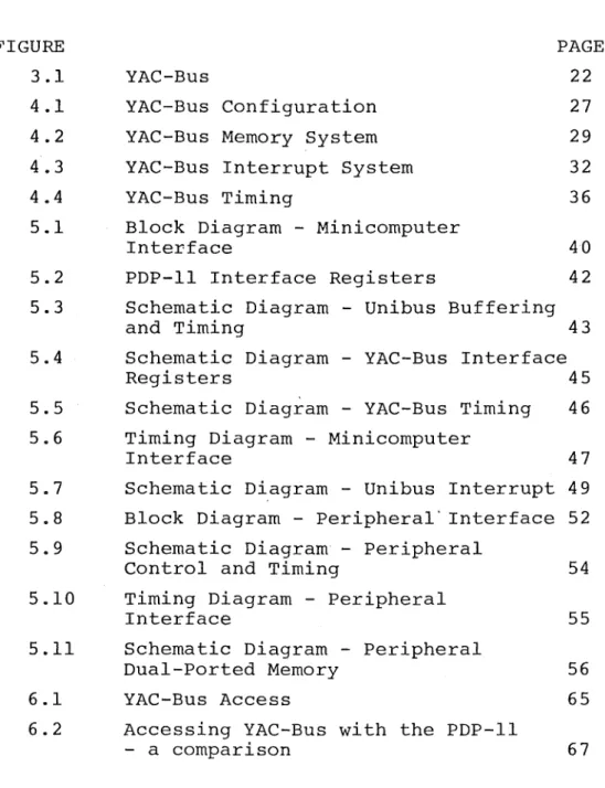
There are two registers provided within the
mini-computer interface that allow the minimini-computer to communicate with a peripheral via YAC-Bus. The index register addresses the peripheral and a byte within its 4k block of YAC-Bus
address space (see figure 4.2). The byte selected by the index register is accessed through another register, the data register. The index register is provided with an auto-incrementing function to make the task of transferring blocks of data more efficient, the contents being incremented after every access of the data register.
eraL
Y--byte
'··'
peri ph
1 - - - -'X'
r
---0 4k 8k
YAC- Bus Memo ry
t
I
Points to memory location
0
I
Contains byte selected by Index Register
Figure
4.2
YAC- Bus Memory System ·
I\.)location
18
19 lA lB lC
·contents
34
45
56
67
78
30.
If we load the·index register with 18, reading the data register will yield the value 34, and reading i t again gives the value of 45. The index register now points to location lA and if we were to read the data register again i t would contain 56. Instead, if we now write FE and ED successively to the data regist~r, our section of memory would have the following contents:
location
18
19 lA lB lC
contents
34
45
FE ED 78
The contents of the data register is now 78 as t~e index register now points to location lC.
Because the data register is only updated at the time the index register is altered, the programmer should be
A third regis~er, the interrupt register, contains information about a peripheral that requests an interrupt to the minicomputer. This register and the operation of the-interrupt system are described in section 4.1.4.
·Certain additional status and control registers are also required - their function and implementation being very machine dependent. These include the control of interrupts from the peripherals and the indication of whether or not the contents of the data and interrupt registers are valid.
4.1.3 THE PERIPHERAL INTERFACE
The peripheral interf~ce consists mainly of a block of dual-ported memory. The memory can be accessed by YAC-Bus or by the peripheral's microprocessor. The
micro-processo~ can access the memory independently of YAC-Bus
except when attempting to interrupt the minicomputer (see the next section) .
An ·access via YAC-Bus has priority over the micro-processor in using this block of memory, even when the memory is being accessed by the microprocessor. This is
to minimise as much as possible the time required to carry out an operation on YAC-Bus. As far as the microprocessor
~
is concerned, during a clash over memory access, the access appears to take longer than usual and only requires of the microprocessor the ability to handle slow memory.
The remainder of the logic within the interface
handles the YAC-Bus signal protocol and the interrupt system insofar as i t affects the peripheral.
4.1.4 THE INTERRUPT SYSTEM
Minicomputer Interface
Interrupt
Register
Per
Ide
-
.
I
I
ipheral
Interrupts
Minicomputer
~
n
•
I
1tification
Minicomputer writes to location 0
I
YAC-Bus
Microprocessor Interface
Peripheral's
block of
YAC-Bus memory
-""""'
1
·----
----0
Micr
writ
loca
oprocessor
es to
tion
1
t
Interrupts
Microprocessor
Figure 4.3
YAC-Bus Interrupt System
w
the same way as a conventional peripheral.
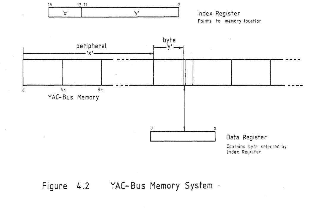
The key to the operatic~ of the interrupt system is the provision of special functions associated with two memory locations in the peripheral's block of memory. For convenience, these are locations 0 and 1 (see figure 4.3). Location 0 may be regarded as a command register. If this location is loaded from YAC-Bus, i t will cause the micro-processor to be interrupted as well as accepting a byte of data. This byte of information is used as a command from the minicomputer to the peripheral.
The function associated with location 1 is somewhat more complex. If written to by the microprocessor, i t will cause YAC-Bus to be accessed. The lower 12 address lines from the microprocessor are just sent through to YAC-Bus
(=001
16), denoting that the peripheral is attempting to interrupt the minicomputer, while the upper 4 address lines are set to the address of the peripheral. The result is to write the byte of data to the interrupt register within the minicomputer interface along with the upper 4 address
bits identifying the peripheral. This byte conveys status or error information. The minicomputer is then interrupted.
A lock associated with the interrupt regisuer prevents its contents from being overwritten until the register has been read'by the minicomputer. The YAC-Bus protocol
(described in the next section) informs the microprocessor if i t has been locked out of the interrupt register and allows i t to attempt further accesses until successful. To be sure that the minicomputer is interrupted by the
peripheral, the microprocessor must keep attempting to write to location 1 until i t is not interrupted.
4.2 YAC-BUS PROTOCOL
Any operation involving YAC-Bus goes through two phases:
i)· gaining control of YAC-Bus
34.
There are many signal protocols that could have been used to control these operations - the protocols being
almost as prolific as computer ·bus systems. A summary of the basic tec~niques used in the control of digital bus structures can be found in Thurber et al [Thurber 72]
Because YAC~Bus is intended to-be used close to a minicomputer, problems associated with the use of long lines
(noise, speed, skew etc) do not arise and simple protocols can be used. Such protocols have to be asynchronous
because the system was designed to be used with a variety of minicomputers and microprocessors, some of them like the PDP-11 being basically asynchronous in nature, and there was no hope of finding common-ground between them to use a synchronous protocol.
The protocols for YAC-Bus are designed to have minimal control requirements and a simple hardware implementation. To achieve some of the simplicity, i t was noted that many protocols have redundant actions and signals that can be combined. The nett result is that the control of YAC-Bus is based on only three signals whose actions are interlinked to some extent with each other and other aspects of the
operation of the bus as a whole.
4.2.1 BUS CONTROL
From previous discussions about the operation of YAC-Bus, the reader should be aware that the minicomputer shares the use of the bus with the peripherals. It is the function of the bus control protocol to unambiguously grant control of YAC-Bus to either the minicomputer or any of the peripherals that request its use. Once control has been granted, i t cannot be preempted in any way until
relinquished by whoever i t was granted to.
updated to reflect such a cha~ge. This requires the
minicomputer interface to gain control of YAC-Bus to retrieve data for the data register.
For most minicomputers there is sufficient time (several instruction cycles) between the altering of the
index register (i.e. supplying an address) and the subsequent accessing of the data register (the time by which the data has to be available) for the interface to await the
completion of the current operation of YAC-Bus and then access the bus itself. In the case of the PDP-11, the timing requirements are more flexible as the Unibus can delay the CPU for up to lOfs to allow data to be processed or become available. This allows several shortcuts to be taken in the design of the miniromputer interface, the details of which will be explained in the next chapter.
The bus-granting mechanism must therefore be under some measure of control by the minicomputer interface and should also.provide a priority system since this controls the relative priority of interrupts from the peripherals.
The bus control method used for YAC-Bus is a variation on that used fairly commonly for priority
handiing within an IO system. It makes use of two control lines, BG (~us ~rant) and BUSY. The BG line is chained through· all the peripheral interfaces connected to YAC-Bus.
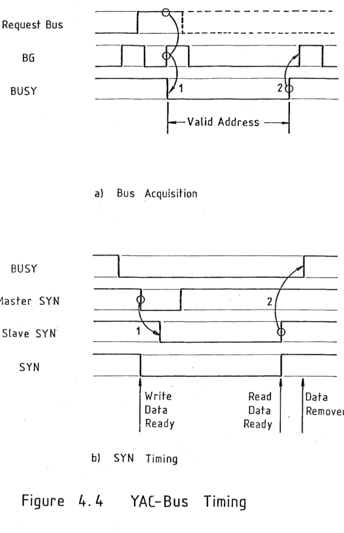
With reference to figure 4.4a, bus control works in the following way:
the BG signal is a series of pulses that originates from the minicomputer interface when YAC-Bus is not being used.
- when a particular peripheral wishes to use YAC-Bus, the low-high transition of BG is blocked at its interface from propagating further along the bus and the peripheral has control of YAC-Bus when the interface receives the low-high BG signal (event 1) .
Request Bus
BG
BUSY
BUSY
Master SYN
Slave SYN.
SYN
2
~Valid
Address
---l
a)
Bus Acquisition
Write
Data
Ready
b)
SYN
Timing
2
Read
Data
Ready
Figure 4. 4
YAC- Bus Timing
36.
Data
- low BUSY stops any further low-high transition of the BG line.
- when the peripheral has finished with YAC-Bus, BUSY is returned high and BG continues pulsing (event 2) .
- since the BG signal originates from the minicomputer interface, that interface has highest priority access to
YAC-Bus. This means that the minicomputer interface can always get control of YAC-Bus immediately the present access cycle has finished.
This bus control system has minimal requirements as regards the number of lines required but is complicated by the timing requirements of the BG signal. To reduce the latency in gaining access to YAC-Bus, the interval between successive BG signals when the bus is not in use should be as short as possible . . This interval, unfortunately, will vary with the application as i t depends on the length of the bus and the delay of the BG signal through the peripheral controllers under worst case conditions. The time must be sufficient to allow the last controller connected to the bus to gain control.
4.2.2 BUS SYNCHRONISATION
Once control has been granted to a minicomputer or peripheral interface, YAC-Bus is then available for a memory access cycle. This is signified by BUSY being pulled low and the memory address being placed on the memory address lines. To avoid possible side effects and spurious
switching, BUSY is used as an enable signal for the
address lines. Synchronisation in addition to that supplied by BUSY is needed as there is the problem of differing speeds between peripherals and the minicomputer interface and,
depending on the microprocessor, there may be some delay before the memory is available for access.
38.
of the two-line handshaking protocol used in the PDP-11 by reducing some of the redundant actions of the MSYN and SSYN signals by using a single line. The function of SYN depends on the fact that i t is an open-collector line and the signal level is the AND function of all the signals placed on the line.
Calling whatever is in control of the bus the 'master' and whatever is being addressed as the 'slave', the protocol works as follows (see figure 4.4b):
a) the master places the address on the bus and then pulses SYN low (event 1) .
b) the slave, in response to the address and SYN, pulls SYN low as well. SYN is held low by the slave until i t has processed the data (carried out a write or read cycle). c) upon receiving high SYN, the master completes the cycle by returning BUSY high, at which time the address and data are removed from the lines (event 2) . The master knows immediately after pulsing SYN whether or not a slave has
responded to the address as SYN would look exactly like master SYN if there was no response, an effect that can be easily detected. This fact has been used in the design .of the minicomputer and peripheral interfaces and in their
interaction. The minicomputer, for instance, can determine if a peripheral exists in a system. More importantly, in the communication between peripheral and minicomputer via the interrupt register in the minicomputer interface, a
lock exists on the interrupt register to prevent its contents from being overwritten. The lock ·on the interrupt register prevents the SYN response from being generated by the mini-computer interface~ this being detected at the peripheral interface and interrupting the microprocessor to·allow i t to attempt to interrupt the minicomputer again.
The time required for a bus cycle can be quite fast. SYN is low for what is essentially the access time of the buffer memory. With the components typically available, tnis access time is of the order of 450ns and can be as
YAC-BUS IMPLEMENTATION
The purpose of this chapter is to describe an
implementation of the minicomputer and peripheral interfaces to YAC-Bus. The interfaces were implemented for a PDP-11 minicomputer and a 6800 microprocessor used as a peripheral controller. The modifications necessary in order to adapt these interfaces for use with other types of minicomputers are also considered.
5.1 THE PDP-11 INTERFACE
The design of the PDP-11 interface had a major constraint - the interface had to fit onto a single board that could be plugged into the backplane of the computer. This limited the number of components ·that could be used in the implement-ation and to some extent influenced the design of YAC-Bus as a whole.
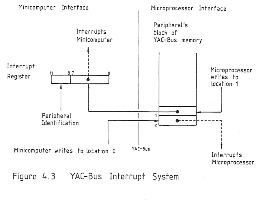
A block diagram of the minicomputer interface is shown in figure 5.1. The interface can be considered to consist of four parts:
i) Unibus buffering and timing providing a) address decoding and buffering b) data buffers and drivers
c) timing of the Unibus MSYN and SSYN signals ii) YAC-Bus Interface Registers consisting of
a) the index register and its YAC-Bus driver
b) the interrupt register and its address comparator c) drivers for the data "register"
d) a multiplexer to present data to the Unibus data drivers.
iii) YAC-Bus timing circuits providing timing for YAC-Bus control signals insofar as they affect the mini-computer interface - they also interact with the Unibus timing as well.
Unibus
Unibus
Buffering
-and
Timing
Unibus
-Interrupt
Figure 5.1 Block Diagram
YAC- Bus
l
YAC- Bus
Interface
Address __Data
Registers
YAC- Bus
Control