Abstract— The visual navigation of mobile robots rely mostly
on road edge detection from images taken from onboard camera. The algorithms used to detect road edges give globally satisfactory results if the scene variability is limited. However, sometimes even if the road edges are properly detected from the input image, the robot guidance task still fails. In this context, this paper investigates the subjective interaction between the scene model and the world model, and we propose a visual control scheme for robot guidance that minimizes the model error induced by processing raw image data. The involved control system includes the fuzzy approach at two levels: a fuzzy perception system which detects efficiently the road edges from the perception-domain image, and a fuzzy control system which uses the knowledge base information and the scene model to control the robot motion. On the other hand, the fuzzy control system is finely tuned through feed-backing mean square errors between the scene model parameters and the knowledge-base data. Hence, a road configuration from a preprocessed image is compared with a fuzzy template made from the fuzzy membership function based on the knowledge base module. Finally, the fuzzy controller uses results of this calculation to guide the robot on the planned path. This paper shows the principle of this system and the simulation results confirming the feasibility of the approach even in the presence of several image artifacts, such as sparse shadows and lighting changes..
Index Terms— Fuzzy Control, Road Edge Detection, Vision
System, Visual Robot Navigation.
I. INTRODUCTION
Most of the research efforts in the visual guidance of autonomous mobile robots have been concentrated on road edge detection. However, less attention has been paid to the after-detection process, especially the physical interpretation of what had been detected. In fact, there is a wide gap between the scene model built based on image processing algorithms and the physical model of the environment where the mobile robot progress. The problem of guiding autonomously a mobile robot in a real environment has attracted many researchers during the last decade [1], [2], [3], [4]. This problem is directly involved with the quality of information provided by mounted sensors which are in reality not perfect. In fact, the quality of edge detection is limited by the raw contents of the image and the edge detecting
Manuscript received January 11, 2008. This work was supported in part by the King Abdul-Aziz City for Science and Technology (KACST) under Grant AT-25-106.
M. Elarbi-Boudihir is with the AI and Robotics Research Laboratory. Computer Science Department, Imam University PO.Box 84880 Riyadh 11681, KSA (Tel/Fax: +966 12582137; e-mail: elarbi@ imamu.edu.sa).
S. F Khelifi is Computer Science Department, King Faisal University KSA (e-mail: [email protected]).
programs processing this image. As a human being, an experimenter knows there is an edge because he is using knowledge in addition to what is contained in the image. How to use such knowledge about the real world in the process of general edge detection is a huge topic that is still under investigation. For example, if the program identifies a road edge and it is likely that it will continue on the other side of a tree branch, then it may have a chance to detect the edge of each and every visible part of a road behind a tree; otherwise, some small and not so obvious pieces of the edge may remain undetected. Consequently, an edge detector may be tailored to take advantage of the domain knowledge. In this context, fuzzy logic allows us to take into account the sensor imperfections. Thus, by using fuzzy measures we can introduce a confidence degree on every source and between sources. Several techniques of data fusion have been proposed to improve the precision of information often perturbed by additive noise, and to reduce the incoherence rate [5], [6]. Furthermore, the choice of any technique is strongly dependent on the environment, sources of information and real time needs. The vision system to find real road edges must be able to operate robustly under a wide variety of environmental conditions including large amount of scene clutters. The clutters can be due to shadows, surface wears, tire skid marks, oil drops, occlusion by other objects, etc. It is difficult to select true edges corresponding to real edges while removing the edges corresponding to irrelevant clutters. A road edge algorithm has been proposed by Nourine et al [7] destined to painted or unpainted road. In this algorithm color cues were used to conduct image segmentation and remove the shadow of the road. Assuming that the roads are normally long and smooth curves, then its can considered as straight lines within a reasonable range for safety. The road edges were detected using Radon transformation applied to the edge image. In the road following phase, a temporal correlation is assumed between successive images. Specifically this algorithm is based on automatic extraction of road position during driving scenarios. Geometrics constraints are assumed on the road contours in order to reduce the search space. Moreover, temporal constraints were assumed in the form of a dynamic focus-of-attention windows in Radon space.
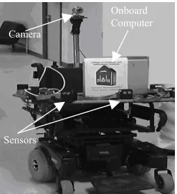
In this paper, we discuss the guidance process for a vision-based autonomous navigation using a fuzzy control approach. As a testing platform we will use a robotic wheelchair system developed for indoor and outdoor use. The robotic wheelchair is equipped with a camera, ultrasound and infrared sensors as illustrated by Figure 1. The development of this robotic wheelchair is part of a research project supported by KACST.
A Neuro-Fuzzy Visual Guidance System for
Autonomous Navigation
Robot
Fuzzy Perception Rf*
Pi
Is O
+ Camera
Platform Motion Target
Image
K Fuzzy Control
System Figure 1: Robotic Wheelchair as testing Platform
The development of the robotic wheelchair aims at improving independent mobility of multi-disabled individuals, and this project focuses on integrating sensory information and human-machine interaction
II. VISUAL NAVIGATION AND SERVOING
The autonomous navigation of mobile robotic systems is actually the objective of a number of research works. The navigation ability in the environment is strictly related to the quality of environment perception. The latter depend on the quantity, quality and reliability of sensors and actuators. The robotic navigation based on visual servoing needs proper image processing algorithms, for connecting actions to visual information. In fact, sensorial processes and motor processes evolve together, by undertaking respectively perceptions and actions, which are considered inseparable, ordered and aimed to the whole cognitive system growing.
Several vision-based road detection and tracking systems uses a model in order to do reliable recognition. The use of models simplifies the detection process, by limiting the search area on specific image-zones and restricted intervals of model parameters. However, many of model-based systems establish some constraints on the environment in order to have a unique solution in the boundaries detection process. In our case, we made the following constraints on the road structure:
• The robot is moving on a flat straight road or with slow curvature (intersections are processed separately).
• The road boundaries are assumed locally parallel.
• The road boundaries are continuous in the image plane, which implies their continuity in the physical world. This constraint makes the prediction of a missing boundary possible (when the boundary detection technique fails).
Moreover, the robot motion is supposed to be “regular”, without abrupt accelerations, which implies generally a temporal correlation between two successive images.
Under such circumstances, we have previously proposed a modular vision system for outdoor autonomous mobile robot navigation [9]. This system uses a visual servoing in which the control incorporates directly the visual feedback in order to guide the robot by detecting the road edges from the image space. The knowledge base module uses the acquired and predicted data to construct a scene model. This model is the main product of the vision system since it reflects the perception of the road edges necessary to a robust and secure
guidance. We have noticed experimentally that relying simply on this model is not sufficient since its derivation was based on an analytical approach. Accordingly, the resulting analytical model involves approximations and simplifications to ensure a solution. Here we introduce a fuzzy system to control the robot motion by considering the scene model parameters as fuzzy variables. The fuzzy parameters such as membership functions of the involved fuzzy variables are consequently tuned according to the knowledge base information. The basic configuration of the developed visual servoing technique is depicted in Figure 2. The approach is specified in terms of regulation in the image frame of the camera. Our application involves the motion control and specifically mobile robot guidance through roadways. This task requires a reliable road edge extraction algorithm which is ensured by the fuzzy perception system. The parameters of the visually perceived features constitute the elements of the state vector which enables to elaborate a fuzzy control model based on the state space representation. This representation is based on the 2D model of both the robot and the perceived scene. It takes into account the visual features of the scene and the modeling of the mobile robot. To realize a servoing technique, the knowledge base establishes a predicted scene model which should be taken as a reference. Hence, Rf* represents a reference target image to
be reached in the image space, Pi the perceived information,
K the gain vector, Is the system input parameters, and finally
[image:2.612.127.254.46.185.2]Os the outputs characterizing the behavior of the robot.
Figure 2: Visual Servoing System
The fuzzy controller uses as input the mean square errors between the parameters of the perceived scene model and those of the corresponding predicted model. The prediction is performed in collaboration between the scene prediction module, the environment map and the knowledge base [8]. To minimize the matching error, a fine tuning of the fuzzy system through feed-backing the mean square errors is performed. Consequently, the knowledge-based control of the mobile robot motion is considered as a hierarchical process involving road edge perception and guidance along a planned path. Most of the processing time is spent with the fuzzy perception module which is based mostly on image transforms. This module operates in two modes: the initial phase which includes all the processing applied to the first image acquired in order to initiate the navigation, and the continuous following mode which handles the processing of subsequent images taken at the end of each blind distance. This distance is linearly proportional to the total processing time. Moreover, the navigation security increases as the blind distance decreases.
III. FUZZY MAPPING AND SCENE MODEL
The perception of the road edges constitutes the most essential feature for the autonomous navigation of the robot. The main idea in our approach is to extract the edges from Camera
Sensors
the perception-domain image. This domain is defined by applying a mapping function on the gradient orientation image. The parameters of the mapping function enabled us to enhance and detect the edges having a specific orientation on the image plane. A prior rough knowledge of the road edge orientation makes it easy to detect it even under uneven conditions. In our work [9],[10], the problem of road edge detection is viewed as a phenomena of perceiving gradient direction levels and then tracing the locus of the vectors which correspond to dominant linear features. We have noticed experimentally that the dominant characteristic of the road edge was its direction since it varies very slowly through the sequence of the input images. Moreover, it is less sensitive to noise than the amplitude of the edge, thus making the fuzzy road edge perception more practical. Accordingly, in order to enhance pixels belonging to the desired intervals of both road edges, we apply a mapping function on the orientation image. This mapping represents a perception of such phenomenon as edge dominance around a predicted direction. Consequently, the detection of the road edges requires a bi-level thresholding around the dominant directions. To determine the thresholds we proceed by measuring the fuzziness of the orientation image using the Yager’s measure[11]. Thus; the minimization of this measure enables to determine the appropriate thresholds levels [12], [13]. The detection of the road edges permits the establishment of the scene model Ms as illustrated by Figure
3.
F
.
φ
δ
λ
Left road edge Rightroad edge image plane
road axis
Figure 3: The Scene Model Parameters
According to this configuration, we express the theoretical aspects of the scene modeling. The output scene model composed of a right and a left road edge may be described by four parameters Ms (F,φ,δ,λ) as shown Figure 3. The physical
parameters Δ and Φ (relative to δ and φ of the scene model) necessary to the robot guidance are determined by the vision system and involved with an uncertainty. Consequently, these parameters may be considered as fuzzy variables, and a fuzzy control system is hooked in the visual servoing system [9].
IV. THE FUZZY CONTROL SYSTEM
The scene is described by the mathematical model Ms
(F,φ,δ,λ). It seems convenient to take care of the fuzzy variables involved in the model through introducing a fuzzy system [16]. A rule base is established by the operator according to a prior knowledge. Nevertheless, the fuzzy parameters such as membership functions of the involved fuzzy variables must be tuned according to the knowledge base information; i.e., predicted data samples. The vanishing point F is defined by its Cartesian coordinates (xv, yv).
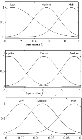
Moreover, fuzziness of variables F, φ, δ and λ is expressed by membership functions established by the operator as
illustrated by Figure 4. The fuzzy system inputs are as follows:
- Inputs 1 and 2 are x and y that specifies F.
- Input 3 and input 5 define the fuzzy variables λ and
δ respectively.
- Input 4 stands for angle φ. Its universe of discourse is variation Δφ around a central value φ0.
The universes of discourse of x, y, δ, and λ are normalized to 1 in order to accommodate any situation. The fuzzy system is then tuned using data of the knowledge base, according to a gradient descent algorithm scheme. Because of the feed-forward structure of the fuzzy systems, the back-propagation algorithm can be used in the same way as for feed-forward multi-layer neural networks. [3].
[image:3.612.353.502.209.658.2]
Figure 4: Membership plots of variables F (x and y), λ, φ, and
δ respectively
Sij represents the fuzzy singleton of output i in the j-th rule.
Hence, the output is expressed by the following:
∑ ∏
∑ ∏
= j k k jk j k ij k jk i x S x y ) ( ). ( μ μWhere we designate the outputs, the fuzzy rules, and the inputs by the indices i,j, and k, respectively. And μjk (xk) is
the membership grade of the input k in the j-th fuzzy rule. To derive the above model, the following fuzzy operations are used:
- The max-product inference scheme is used for evaluating the overall output fuzzy set.
- The output fuzzy sets are distinct singletons.
- The centroid defuzzification scheme is used to produce a single numerical output from the resulting output fuzzy set.
The membership functions are Gaussian functions:
⎟⎟ ⎟ ⎠ ⎞ ⎜⎜ ⎜ ⎝ ⎛ − − = 2 2 2 exp ) ( jk jk k k jk m x x σ μ
Where mjk and σjk are the mean and standard deviation,
respectively.
The error measure of interest is the sum squared errors between the desired parameter T provided by the knowledge base at any instant, and that produced by the fuzzy system (y) over all the training pairs (Yp,Tp). This error is given as
follows:
(
)
∑∑
−
=
p i p i p iy
t
E
22
1
Where yip is the i-th output generated by the fuzzy system for
the p-th input.
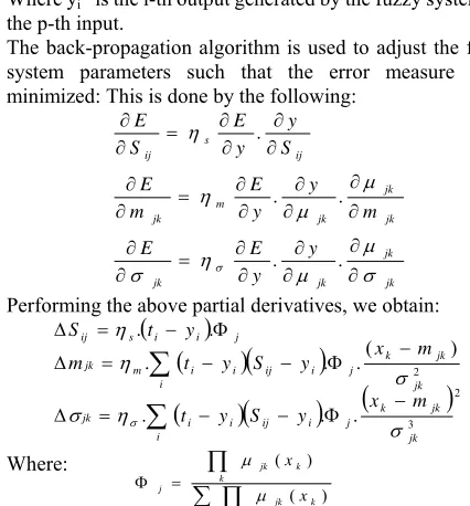
The back-propagation algorithm is used to adjust the fuzzy system parameters such that the error measure E is minimized: This is done by the following:
jk jk jk jk jk jk jk m jk ij s ij y y E E m y y E m E S y y E S E σ μ μ η σ μ μ η η σ ∂ ∂ ∂ ∂ ∂ ∂ = ∂ ∂ ∂ ∂ ∂ ∂ ∂ ∂ = ∂ ∂ ∂ ∂ ∂ ∂ = ∂ ∂ . . . . .
Performing the above partial derivatives, we obtain:
(
)
(
)
(
)
(
)
(
)
(
)
∑
∑
− Φ − − = Δ − Φ − − = Δ Φ − = Δ i jk jk k j i ij i i jk i jk jk k j i ij i i m jk j i i s ij m x y S y t m x y S y t m y t S 2 3 2 . . . ) ( . . . . . σ η σ σ η η σ Where:∑ ∏
∏
= Φ j k k jk k k jk j x x ) ( ) ( μ μwhich represents the normalized activation of rule j, and ηs ,
ηm and ησdenote the learning rates of the respective fuzzy
parameters. The determination of the normalized activation
Φj can be regarded as a procedure for selecting suitable
features. The self-tuning architecture of the fuzzy system is given by Figure 5.
The predicted model Mp produced by the knowledge base
is used by the geometrical reasoning module in order to obtain a 3-D interpretation necessary to the pilot module.
This interpretation reflects the predicted orientation error Φp
and the predicted shift error Δp. On the other hand, the fuzzy
perception system provides the measured scene model Ms .
The fuzzy systems are constructed and tuned so to match the system model of the knowledge base (predicted) with the system model Ms (measured). The Fuzzy systems 1 and 2 tune
the control variables Φ and Δ by back propagating the mean square errors between Ms and Mp. The iteration process of the
[image:4.612.321.553.176.357.2]controller halts when the estimated error reaches its minimal acceptable value generally prefixed by the operator.
Figure 5: Tuning schema of the fuzzy system through feed-backing mean square errors εΔand εΨ.
The error variations through the tuning process are shown by Figure 6. Up to 100 epochs, the overall fuzzy system is supposed well tuned and εΨand εΔreach εΨmin=2.10-3 and
εΔmin= 10-5 respectively. The resulting membership functions
after fine tuning using back propagation are illustrated by Figure 7.
ErrorεΦ Errorε
Δ
0 20 40 60 80 100
2 2.2 2.4 2.6 2.8
x 10-3
Epochs
Error Curves
Figure 6: Tuning process through error curves
Fuzzy System 1
Fuzzy System 2 The Fuzzy Perception System Knowledge Base Mp xp yp φp δp λp Ms x y φ δ λ Geometrical Reasoning Module Φp
Φs +
εΦ
Δs +
εΔ
[image:4.612.67.280.394.623.2][image:5.612.115.259.50.295.2]
Figure 7 : Membership functions after fine tuning using back-propagation.
This controller is supposed to generate control values Φ
and Δ with a high degree of accuracy even in presence of uncertain measured model parameters. The rule base is constructed by the expert (upon a prior knowledge). In general, there are 35 possible rules. For illustration, only
relevant rules are chosen so to infer output control values Φ
and Δ. as shown in Figures 8 and 9 for the normalized outputs
Δ and Φ respectively. These surface views are very useful especially during the calibration phase since they enable to determine easily the different parameters minimizing the output guidance parameters. One may easily notice from Figure 8 that minimizing the parameter Δ would correspond to x=y=0.5 (which corresponds to a vanishing point centered on the image plane) with δ approaching zero. The same conditions would be true for minimizing Φ but with φ
approaching zero (see Figure 9).
[image:5.612.325.529.50.196.2]
Figure 8: Some Surface views of normalized output Δ
produced by the fuzzy controller.
Figure 9: Some surface views of output Φ produced by the fuzzy controller.
More, with the help of the used data structures and the representation of the membership functions in continuous, we obtain a O(n) calculation (with n the number of fuzzy partitions) that fit the sense of the real time objective fixed.
V. EXPERIMENTAL RESULTS
In order to evaluate the effectiveness of this approach, a series of 250 images (indoor and outdoor scenes) were tested. These images taken by a CCD camera are 256x256 in size with 256 gray levels. In case no vanishing point Fi is found, the supervisor identifies this situation as a complete failure and asks for a modification of the parameters of the camera-robot configuration. These relations may also be used for the calibration of the camera. Using the Parameters of the robot-camera configuration and considering a set of 80 images describing a real trajectory in the robot environment, the parameters of the scene model Ms and
world model Mp were given by the fuzzy controller. The
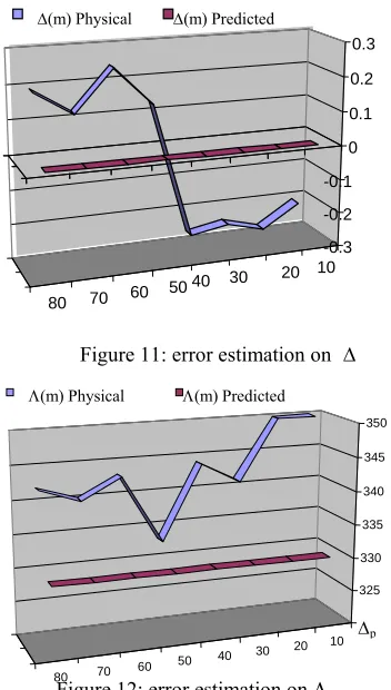
[image:5.612.80.289.525.664.2]error on orientation parameter Θ were evaluated to be less than 5.31% as shown on Figure 10. Another set of 80 images were chosen were the road axis shift error Δ is predicted to be zero, the fuzzy controller minimizes the error down to 2.7% (see Figure 11). Finally, for the road width Λ Figure 12 shows the results on 80 images where the road width is predicted to be 3.3m, the error on that assumption is about 6.06%.
Figure 10: error estimation on Θ
10 20 30 40 50 60 70 80
θ(°) -20
-15 -10 -5 0 5 10 15 20
[image:5.612.332.510.549.699.2]Figure 11: error estimation on Δ
Figure 12: error estimation on Λ
VI. CONCLUSION
In this paper a scheme is proposed for the control of mobile robot motion using visual guidance. The involved control system includes the fuzzy approach at two levels: a fuzzy perception system which detects efficiently the road edges from the perception-domain image, and a fuzzy control system which uses the knowledge base data and the scene model to produce an efficient control model with minimized errors for guiding the robot. More attention has been focused on the after-detection process which uses a fuzzy system to minimize the error between the physical and predicted models. The efficiency of the proposed scheme leads to the enhancement of the ability and the adaptability of the mobile robot guidance in real complex environment. This has been shown through the encouraging practical results obtained in the indoor and outdoor autonomous navigation of our robotic wheelchair.
REFERENCES
[1] R. R. Murphy, Introduction to AI Robotics. Cambridge, MA: MIT Press, 2000.
[2] A. Saffiotti, “The uses of fuzzy logic in autonomous robot navigation,” Soft Comput., vol. 1, no. 4, pp. 180–197, 1997.
[3] Chin Teng, C.G. Lee . Neural Network Based Fuzzy Logic Control and Decision Systems. IEEE Transactions on Computers, Vol. 40, N°12, Dec 1991.
[4] M. Mucientes, R. Iglesias, C. V. Regueiro, A. Bugarini, and S. Barro, “A fuzzy temporal rule-based velocity controller for mobile robotics,” Fuzzy Sets Syst., vol. 134, pp. 83–99, 2003.
[5] L. Foulloy, S. Galichet. Fuzzy Sensors for Fuzzy Control. Int Journal of Uncertainty, Fuzziness and Knowledge Based System. Vol. 2, N° 1, 1994.
[6] Rachid. Nourine, M.E. Boudihir, S. Khelifi, "Lane boundaries detection and following using Radon Transform," In Proceeding of the
IEEE/APS Conference on Mechatronics and Robotics, Aachen, Germany, September 13-15,2004, pp. 888-893.
[7] M. Elarbi Boudihir, M. Dufaut, R. Husson. Map Database Construction and Scene Prediction for Visual Navigation. Engineering Systems with Intelligence. ISBN 0-7923-1500-6. Kluwer Academic Publishers 1999. pp 357-365.
[8] M. Elarbi-Boudihir, R. Nourine, “Visual Guidance of Autonomous Vehicle Based on Fuzzy Perception”. IEEE International Conference on Intelligent Vehicles IV’98. 28-30 October 1998. Stuttgart, Germany. Vol 1, Pp 23-28.
[9] A.Rahmoun, M.Elarbi-Boudihir. “ New GA/NN based-Methodologies to Derive Optimal Fuzzy Systems ”, Arabian Journal of Sciences and Engineering AJSE (KSA). Vol 25 N° 1B April 2000. Pp 223-240. [10] D. Burschka and G. Hager, “Vision-based control of mobile robots,” in
Proc. IEEE Int. Conf. Robot. Autom., Seoul, Korea, May 2001, pp. 1707–1713.
[11] J. Chen, A. Behal, D. Dawson, and Y. Fang, “2.5D visual servoing with a fixed camera,” in Proc. IEEE Amer. Control Conf., Denver, CO, June 2003, pp. 3442–3447.
[12] M.M Gupta, G.K Knopf, P.N Nikiforuk. Computer Vision with Fuzzy Edge Perception. Proceedings of the IEEE International Symposium on Intelligent Control 1987. Pp 271-278. January 1987. Philadelphia, Pennsylvania.
[13] S. Galichet, L. Foulloy. Fuzzy Control- Fuzzy Controllers: Synthesis and Equivalences. IEEE Transactions on Fuzzy Systems, Vol. 3, N°2, 1995, pp 140-148.
[14] A. Bonarini, “Evolutionary learning of fuzzy rules: Competition and cooperation,” in Fuzzy Modelling: Paradigms and Practice, W. Pedrycz, Ed. Norwell, MA: Kluwer Academic, 1996, pp. 265–284. [15] M. Mucientes, D. L. Moreno, C. V. Regueiro, A. Bugarini, and S. Barro,
“Design of a fuzzy controller for the wall-following behavior in mobile robotics with evolutionary algorithms,” in Proc. Int. Conf. Inf. Process. Manage. Uncertainty Knowledge-Based Syst. (IPMU’2004), Perugia, Italy, 2004, pp. 175–182.
[16] H. Hagras, V. Callaghan, and M. Collin, “Learning and adaptation of an intelligent mobile robot navigator operating in unstructured environment based on a novel online fuzzy-genetic system,” Fuzzy Sets Syst., vol. 141, pp. 107–160, 2004.
[17] K. Izumi, K. Watanabe, and S.-H. Jin, “Obstacle avoidance of mobile robot using fuzzy behavior-based control with module learning,” in Proc. 1999 IEEE/RSJ Int. Conf. Intell. Robots Syst., 1999, pp. 454–459.
[18] S. Yamada, “Evolutionary behavior learning for action-based environment modeling by a mobile robot,” Application. Software Computation., pp. 245–257, 2005.
[19] T. Dahl and C. Giraud-Carrier, “Evolution-inspired incremental development of complex autonomous intelligence,” in Proc. 8th Int. Conf. Intelligent. Autonomous. Systems. (IAS’04), Amsterdam, The Netherlands, 2004, pp. 395–402.
[20] C. K. Lin, “A reinforcement learning adaptative fuzzy controller for robots,” Fuzzy Sets Syst., vol. 137, pp. 339–352, 2003.
[21] D. Gu, H. Hu, and L. Spacek, “Learning fuzzy logic controller for reactive robot behaviours,” in Proc. 2003 IEEE/ASME Int. Conf. Adv. Intell. Mechatron. (AIM 2003), 2003, pp. 46–51.
[22] H. R. Beom and H. S. Cho, “A sensor-based navigation for a mobile robot using fuzzy logic and reinforcement learning,” IEEE Trans. Syst., Man, Cybern., vol. 25, no. 3, pp. 464–477, 1995.
[23] Y. Takahashi and M. Asada, “Multi-layered learning systems for vision-based behavior acquisition of a real mobile robot,” in Proc. SICE Annu. Conf. 2003, 2003, pp. 2937–2942.
10 20 30 40 50 60 70 80
-0.3 -0.2 -0.1 0 0.1 0.2 0.3
Δ(m) Physical Δ(m) Predicted
70 80
10 20 30 40 50 60
Δp