Abstract— The most common devices used to control access to private areas where sensitive work is being carried out or where data is held, are keys, badges and magnetic cards. These all have the same basic disadvantages: they can easily be duplicated and when stolen or passed on, they can allow entry by an unauthorized person. This paper proposed a low cost embedded controller based smart card which consists of contact less card and a card reader. This Card reader is ideal for applications such as access control, attendance monitoring etc.
Index Terms—Contactless Smart card, Control Algorithm Embedded Controller, MAX 232.
I. INTRODUCTION
A smart card is like an “electronic wallet”. Imagine the power of a computer, the speed and security of electronic data, and the freedom to carry that information anywhere on earth. Imagine a computer so small it fits inside a plastic card like the credit card you carry in your wallet. Smart card technology has been around for more than 20 years. Since its first introduction into the market, its main application is for the payphone system. As card manufacturing cost decreased, smart card usage has expanded. In May 1996, several companies including Microsoft, Hewlett-Packet and Schlumberger formed a PC/SC workgroup which aimed at integrating the smart card with personal computer (PC). This workgroup mainly concentrates on producing a common smart card and PC interface standards for the smart card and PC software producers. Many of the interface standards and hierarchy have already been established. Some of these prototype products are now available on the market [1]. The security requirements of smart cards in personal communication system are two folds; they are authentication & protection of information. This paper deals with matter pertaining to the application of IC cards (or smart cards) in the security of personal communication system. Security advantages achieved by the use of smart cards in security system are discussed. Smart card is required to perform three fundamental functions -
1) To communicate with a host device 2) To store data
3) And to process data received by and stored in the card
Vivek Kumar Sehgal is with Department of Electronics and Communication Engineering, Jaypee University of Information Technology, Waknaghat, Solan, Himachal Pradesh, INDIA (E-mail: [email protected]). Nitin, is with Department of Computer Science Engineering and Information Technology, Jaypee University of Information Technology, Waknaghat, Solan, Himachal Pradesh, INDIA (E-mail: [email protected], and [email protected]).
Durg Singh Chauhan is Presently Vice Chancellor and Professor in Department of Computer Science Engineering and Information Technology, Jaypee University of Information Technology, Waknaghat, Solan, Himachal Pradesh, INDIA (E-mail: [email protected]).
Fig.1. Smart Card Internal Architecture
In general smart cards conform to a standard architecture. The key element in proposed architecture is a microcontroller, ROM, RAM, EEPROM & a infra red communication interface as shown in Fig. 1. There are two types of smart cards contact or contact less [2-3]. Smart cards are defined according to the type of chip implanted in the card and its capabilities. There is a wide range of options to choose from while designing a particular system as shown in Fig. 2.
Fig.2. Types of Smart Cards
The organization of the paper is as follows: In section 2, we discuss the proposed design that also presents the block diagram for our proposed system. Detailed circuit description
Embedded Controller Based Smart Card Access
is provided for each block used in this section. In section 3, we present the software implementation along with flow diagram. In section 4, PCB designing, actual circuit implementation on PCB and simulated schematic are shown. Finally, some conclusions are offered in section 5
II.PROPOSED WORK
This system has two parts- one is contact less card and another is card reader. Card reader is ideal for applications such as access control, attendance monitoring etc. There are predefined codes for every card. Codes are stored in the micro controller’s memory. Micro controller has inbuilt EEPROM so it uses inbuilt EEPROM to store the code for a user. EEPROM technology features low voltage capability, an EEPROM endurance of 100,000 write/erase cycles, a ten year EEPROM data retention and over 5000V of ESD protection, thereby ensuring safe storage of the card data throughout the lifetime of the card. Each micro controller is programmed for a specific predefined code thus each user will have a unique code. Whenever a user attempt card &press the switch present on card, in front of card reader at 6 inches of distance, code stored in the memory is transmitted serially from the micro controller to power amplifier. And power amplifier makes it capable to be fed to the IR transmitting LED. Fig. 3. Shows the block diagram of card
Fig.3. Block Diagram of Card
Card reader, from the card at baud rate of 9600bps receives codes. Infrared receiver works in positive logic i.e. when the IR light falls on it, its output goes high and when the IR light doesn’t fall on it, its output goes low. Receiver passes these codes to the PC. MAX 232 will make it compatible with PC. The software will check and compare the code received. If the code is present in the database then it will switch on the electromagnetic relay circuitry using parallel port. Otherwise it will give a message on screen or make a sound buzzer on. If the code matches as there in database, then it will open the door using stepper motor. Make the power supply on for a particular cabin. And make the attendance record on the basis of time [4]. Fig.4. Shows the block diagram of card reader Basic components used for designing of “IR Based Secure Electronic Access System Using Microcontroller” are:
1) Power supply source 2) Microcontroller (8051) 3) Max 232
4) Infrared emitting diode 5) Infrared photodiode 6) Optocoupler (MCT-2E) 7) Electromagnetic relay (SPDT
Fig.4. Block Diagram of Card Reader
A.MAX 232 (Communication Interface)
RS-232 (Fig. 5.) was created for one purpose, to interface between Data Terminal Equipment (DTE) and Data Communications Equipment (DCE) employing serial binary data interchange. So as stated the DTE is the terminal or computer and the DCE is the modem or other communications device. RS 232 is the most widely used serial I/O interfacing standard. In RS 232, a 1 is represented by -3 to -25 v. while a 0 bit is +3 to + 25 v, making -3 to +3 undefined. For this reason, to connect any RS 232 to a microcontroller system we must use voltage converters such as MAX 232 to convert the TTL logic levels to the RS 232 voltage level, and vice versa. This chip is used when interfacing micro controller with PC to check the Baud rate and changes the voltage level because micro controller is TTL compatible whereas PC is CMOS compatible.
Fig.5. Operating Circuit of MAX 232
B.Optocoupler (MCT-2E)
devices such as thyristors, triacs etc. To carry a signal across the isolation barrier, optocouplers are operated in linear mode. Fig.6. Shows the six-pin IC package for an optocoupler and the electronic diagram of its pin outline
Fig.6. MCT-2E Pin Diagram
C.Electromagnetic Relay
The electromagnetic relay consists of a multi-turn coil, wound on an iron core, to form an electromagnet as shown in Fig.7. When the coil is energized, by passing current through it, the core becomes temporarily magnetized. The magnetized core attracts the iron armature. The armature is pivoted which causes it to operate one or more sets of contacts. When the coil is de-energized the armature and contacts are released.
Fig.7. Electromagnetic Relay
III. SOFTWAREIMPLEMENTATION
To evaluate the software for correct operation the file was programmed into the microcontroller on the relevant development board. Programming of the microcontroller was achieved using MP5 software. EZ31 is an EEPROM programmer that interfaces directly with the computer serial port. This permits hexadecimal files to be loaded into the microcontroller. Initially the micro controller was programmed by removing it from the socket on the board and inserting it into the multi-pin socket on the programmer. The software burned in the embedded processor is described by the following flow charts (Fig. 8-11).
Fig.8. Flow Chart for Serial Transmission & Card
Fig.9. System Flow Chart
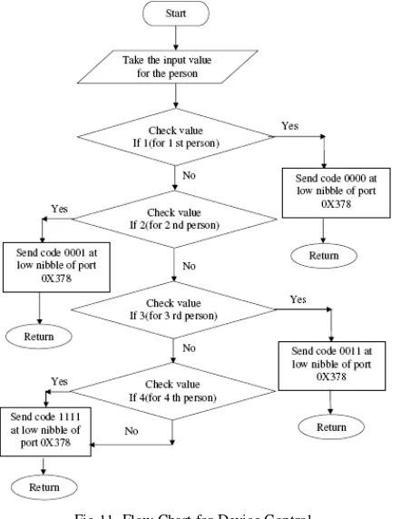
Fig.11. Flow Chart for Device Control
IV. HARDWARE IMPLEMENTATION AND SCHEMATIC
DESCRIPTION
The implemented work is shown in Fig.12
Fig.12. Complete Application
Wireless infrared communication systems enjoy significant advantages over radio systems in certain environments. First, there is abundance unregulated optical spectrum available. This advantage is shrinking somewhat as the spectrum available for licensed and unlicensed radio systems increase due to modernization of spectrum allocation policies. Radio systems must make great efforts to overcome or avoid the effects of multipath fading, typically through the use of diversity. Infrared systems do not suffer from time-varying fades due to the inherent diversity in the receiver. This simplifies design and increases operational reliability. Infrared system provides a natural resistance to eavesdropping, as the signals are confined within the walls of the room. This also reduces the potential for neighboring wireless communication systems to interfere with each other,
which is a significant issue for radio-based communication systems. This signal confinement makes it easy to secure transmissions against casual eavesdropping, and it prevents interference between links operating in different rooms. Infrared is favored for short-range applications in which per-link bit rate and aggregate system capacity must be maximized, cost must be minimized, light weight, moderate data rates ,international compatibility is required, or receiver signal-processing complexity must be minimized [5].
Infrared
Other Wireless
Technology
Typical range Short range wireless point-n-shoot data exchange and network access
Long range wireless data exchange and network access
Interference None Other RF devices,
building material, equipment Security Very secure due to
short range and line of sight.
Less secure
Power consumption
Low High
Real-time network access application
Requires user to walk up to an access point.
User does not have to be near an access point.
Range 1 meter 10 meter,1oo meter
Line of sight Yes No
Component cost
Low High
Ckt design Simple Complicated
[image:4.612.312.558.155.623.2]Portability portable No
Table 1. Comparison of Wireless Technologies
- +
D1
RS407L
2
1
3
4 C1
CAPACITOR T1
TRANSFORMER
1 5
4 8
2
2
0
V
U9
LM7805/TO VIN
1
VOUT 2
0
VCC 1
[image:4.612.89.281.397.553.2]Title
Size Document Number Rev
Date: Sheet of
<Doc> <Rev Code>
<Title> B
1 1
Friday , August 08, 2008
0 J9 JUMPER 1 2 0 0 VCC 1 VCC 2 MG1 MOTOR STEPPER 1 2 3
4 5 6
LS1 RELAY SPDT 3 5 4 1 2 LS2
RELAY SPDT
3 5 4 1 2 LS3 RELAY SPDT 3 5 4 1 2 LS4 RELAY SPDT 3 5 4 1 2 J7CON9
123456789
Q4 Q5 Q6 Q7
Q8 Q9 Q10
Q11 U1 MCT2E 1 6 2
5 4 U2
MCT2E
1
6
2
5 4 U3
MCT2E
1
6
2
5 4 U4
MCT2E 1 6 2 5 4 U5 MCT2E 1 6 2 5 4 U6 MCT2E 1 6 2
5 4 U7
MCT2E
1
6
2
5 4 U8 MCT2E 1 6 2 5 4 J8 CON25
12345678910111213145116171819022122232425 R1 RESISTOR R2 RESISTOR R3 RESISTOR R4 RESISTOR R5 RESISTOR R6 RESISTOR R7 RESISTOR R8 RESISTOR
Fig.14. Schematic Diagram of Device Control and Door Opening
U1 8051 PSEN 29 ALE 30 VCC 40 EA 31 X1 19 X2 18 RST 9 P0.0/AD0 39 P0.1/AD1 38 P0.2/AD2 37 P0.3/AD3 36 P0.4/AD4 35 P0.5/AD5 34 P0.6/AD6 33 P0.7/AD7 32 P1.0 1 P1.1 2 P1.2 3 P1.3 4 P1.4 5 P1.5 6 P1.6 7 P1.7 8 P2.0/A8 21 P2.1/A9 22 P2.2/A10 23 P2.3/A11 24 P2.4/A12 25 P2.5/A13 26 P2.6/A14 27 P2.7/A15 28 P3.0/RXD 10 P3.1/TXD 11 P3.2/INT0 12 P3.3/INT1 13 P3.4/T0 14 P3.5/T1 15 P3.6/WR 16 P3.7/RD 17 Q1 BC547 0 D1 LED 470 R1 1B 1n C1 1n C2 1n C3 470 R2 1B Y 1 CRYSTAL 0 J1 JUMPER1 1 2 LCD
1 2 3 4 5 6 7 8 9 10 11 12 13 14 15 16
0 0 VCC VCC VCC VCC U2 LM7805/TO VIN 1 VOUT 2 0 J5 JUMPER1 1 2
U3
MAX232/SO C1+ 1
C1-3
C2+ 4
C2-5
V+ 2
V-6
R1OUT 12
R2OUT 9
T1IN 11
T2IN 10
R1IN 13
R2IN 8
T1OUT 14
T2OUT 7
0 C4
VCC C5
C6
J2
CON9 1 2 3 4 5 6 7 8 9 1k
R3
1B 10k
R4
1B
10k R5
1B
J3
JUMPER1
1 2
0 VCC
D1 IR DIODE
Q2 BC547
Q3 BC547
0
- +
D2
RS407L
2
1
3
4
C7 CAPACITOR T1
TRANSFORMER
1 5
4 8
2
2
0
V
U4
LM7805/TO VIN 1
VOUT 2
0
VCC
Fig.16. Schematic Diagram of IR Reader Circuit
V.CONCLUSION AND FUTURE SCOPES
In this microcontroller based secure access system used core is ATMEL’S 89C51 program executed by the card's microcontroller is written in EEPROM at the mask-producing stage and can be modified in any way. This guarantees that the code is strictly controlled by the manufacturer. For storing user-specific data, individual to each card, the first generation of non-volatile memories used EPROM’s which required an extra "high" voltage power supply (typically from 15 V to 25 V). This access system only contain EEPROM which requires a single 5 V power supply (frequently that of the microcontroller) and can be written and erased thousands of times (cycles). Finally, a communication port (serial via an asynchronous link) for exchanging data and control information between the card and the external world is available. A common bit rate is 9600 bit/s a first rule of security is to gather all these elements into a single chip. Contact less technology brings many benefits to secure ID systems when factors such as high throughput and usage, harsh environments, and reader maintenance and reliability are important. Because the contact less card chip and the reader communicate using infrared waves, there is no need to physically make an electrical connection. Maintenance of reader is minimized while reliability is improved since there are no worn contacts to be replaced or openings to be unblocked. Cards also last longer because removing them from their regular carrying place is not necessary for use.
The key benefits of using contact less smart card technology for physical access are summarized below.
1) High speed of access and high throughput 2) Useable in harsh or dirty environments 3) User friendly
a) Less intrusive
b) Does not require insertion of the card into the reader
c) No issues with orientation of the card d) May be kept in wallet or purse for personal
security during use
This is just the beginning; soon it will influence the way we shop, see the doctor, and even enjoy leisure. Contact and contactless technologies can be implemented on one card in future.
REFERENCES
[1] Dr. Marc Lassus, “smart cards: accost effective solution against
electronic fraude,” no.437, IEE 1997.
[2] C.A.Pinto, A.C.Borim, J.M.Fernandes, A.R. Ferreira “Wireless implementation for access control to restricted areas,” IEEE Transaction
vol.1-5, no.7803, pp.1078-1081, 1999.
[3] F.Y, Yang and J.K.Jan “A provable secure access control using smart
cards,” IEEE Transaction vol, 13, no.3, July 10, 2003.
[4] IBM Redbook “Smart Card Case Study”