© 2019, IRJET | Impact Factor value: 7.34 | ISO 9001:2008 Certified Journal
| Page 194
Modelling & Analysis of Drill Bit with different Materials
Shivani
1, Dr. L.P. Singh
2, Alok Yadav
31
M. Tech Student, Production & Industrial Engg. (Mechanical Engineering Dept.), SHUATS, Allahabad, India
2Associate Professor, Production & Industrial Engg. (Mechanical Engineering Dept.), SHUATS, Allahabad, India
3
M. Tech Student, Production & Industrial Engg. (Mechanical Engineering Dept.), SHUATS, Allahabad, India
---***---Abstract -Bit selection is considered to be an importanttask in drilling optimization process. To select a bit is considered as an important issue in drilling. In the present work we have considered a twist drill bit of HSS material as a model for getting the results compared to get more safe and efficient material from beta titanium alloy and alpha titanium alloy. Modelling of drill bit is done on SOLIDWORKS 2018 and the analysis is being performed on the ANSYS WORKBENCH 19.2 software. The geometrical shape and input process conditions are same for both materials. The titanium alloy which is widely used in the field of biomedical applications is being examined with the HSS which is mostly applicable in majority of the applications. According to the analysis results, it is observed that the beta titanium alloy is showing the maximum effective strain with minimum equivalent stress as compared with alpha titanium alloy.
Key Words: Drill bit, ANSYS WORKBENCH 19.2,
SOLIDWORKS, beta and alpha titanium alloy.
1. INTRODUCTION
Drilling is the process most commonly associated with producing machined holes, because it is simple, quick and economical. Drilling is one of the most complex machining processes. The chief characteristic that distinguishes it from other machining operations is its angle tool. Drilling is one of the basic machining process of making holes and it is essentially for manufacturing industry like Aerospace industry, watch manufacturing industry, Automobile industry, medical industries and semiconductors. Especially Drilling is necessary in industries for assembly related to mechanical fasteners. It is reported that around 55000 holes are drilled as a complete single unit production of the Air bus A350 aircraft. The challenged of new modern machining industries is focusing on the gaining of high quality, in term of work piece dimensional accuracy, surface finishing, very high production rate, less wear on the cutting tools and in the term of economy of the cost saving. Manufacturing enterprises presently have to deal with increasing demands for improved product quality, tool life, less wear and cutting force. In today’s fast changing situation in manufacturing industries, applications of optimization techniques in metal cutting processes is necessary for a manufacturing unit to work effectively to severe competitiveness and growing demand of quality product in the market.
1.1. Nomenclature of the twist drill bit:
Drill: A drill is an end-cutting tool for producing holes. It has one or more cutting edges, and flutes to allow fluids to enter and chips to be ejected. The drill is composed of a shank, body and point.
Shank: The shank is the part of the drill that is held and driven. It may be straight or tapered.
Tang: The tang is a flattened portion at the end of the shank that fits into a driving slot of the drill holder on the spindle of the machine.
Body: The body of the drill extends from the shank to the point, and contains the flutes. During sharpening, it is the body of the drill that is partially ground away.
Point: The point is the cutting end of the drill.
Flutes: Flutes are grooves that are cut or formed in the body of the drill to allow fluids to reach the point and chips to reach the workpiece surface. Although straight flutes are used in some cases, they are normally helical.
Land: The land is the remainder of the outside of the drill body after the flutes is cut. The land is cut back somewhat from the outside drill diameter to provide clearance.
Margin: The margin is a short portion of the land not cut away for clearance. It preserves the full drill diameter.
Web: The web is the central portion of the drill body
that connects the lands.
Chisel edge: The edge ground on the tool point along the web is called the chisel edge. It connects the cutting lips.
Lips: The lips are the primary cutting edges of the drill. They extend from the chisel point to the periphery of the drill.
Axis: The axis of the drill is the centerline of the tool. It runs through the web and is perpendicular to the diameter.
Neck: Some drills are made with a relieved portion between the body and the shank. This is called the drill neck. In addition to these terms that define the various parts of the drill, there are a number of terms that apply to the dimensions of the drill, including the important drill angles. Among these terms are:
© 2019, IRJET | Impact Factor value: 7.34 | ISO 9001:2008 Certified Journal
| Page 195
Body diameter clearance: The height of the step fromthe margin to the land is called the body diameter clearance.
Web thickness: The web thickness is the smallest dimension across the web. It is measured at the point unless otherwise noted. Web thickness will often increase in going up the body away from the point, and it may have to be ground down during sharpening to reduce the size of the chisel edge. This process is called "web thinning."
Helix angle: The angle that the leading edge of the land makes with the drill axis is called the helix angle. Drills with various helix angles are available for different operational requirements.
Point angle: The included angle between the drill lips is called the point angle. It is varied for different workpiece materials.
Lip relief angle: Corresponding to the usual relief angles found on other tools is the lip relief angle. It is measured at the periphery.
Chisel edge angle: The chisel edge angle is the angle between the lip and the chisel edge, as seen from the end of the drill.
Fig - 1 Twist drill bit geometry.
2. MATERIALS & METHOD
Bit selection, like the selection of the correct WOB, RPM and hydraulics, is dependent upon a degree of trial and error. Unfortunately, there is no fool proof method of selecting the best available drilling bit for the formations to be drilled. The aim of any bit selection programme is to reduce the trial and error to a minimum. There are many proposed methods for bit selection and often more than one is used before reaching a decision. Bit selection methods include:
Cost analysis
Dull bit evaluation
Offset well bit record analysis
Offset well log analysis
IADC bit coding
Manufacturers' product guides
Geophysical data analysis
General geological considerations
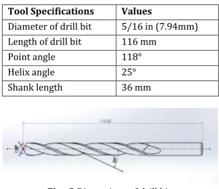
The drill-bit model which is used in this analysis is of twist drill bit type. The standard diameter of this type of drill-bit is 8mm. The point angle and flute length are 118° and 80 mm respectively.
Table -1 Drill bit specifications
Tool Specifications Values
Diameter of drill bit 5/16 in (7.94mm)
Length of drill bit 116 mm
Point angle 118°
Helix angle 25°
[image:2.595.34.288.87.524.2]Shank length 36 mm
Fig - 2 Dimensions of drill bit.
[image:2.595.323.543.236.425.2]2.1 Design of drill bit using SOLIDWORKS Software A 3D model of the twist drill bit with given specifications was drawn using SOLIDWORKS with the dimensions shown in Table 1.
[image:2.595.351.518.502.671.2]Fig - 3 Horizontal view of drill bit.
Fig - 4 Isometric view of drill bit.
[image:2.595.373.497.592.659.2]© 2019, IRJET | Impact Factor value: 7.34 | ISO 9001:2008 Certified Journal
| Page 196
the physical and material properties, meshing was carried out. Number of nodes was 2110 and number of elements was 1003 of drill bit after meshing is shown in Fig. The model was then solved for the required output data.
2.2 Meshing the model: Meshing is probably the most important part in any of the computer simulations, because it can show drastic changes in results you get. Meshing means you create a mesh of some grid-points called 'nodes’. It's done with a variety of tools & options available in the software.
The results are calculated by solving the relevant governing equations numerically at each of the nodes of the mesh. The governing equations are almost always partial differential equations, and Finite element method is used to find solutions to such equations. The pattern and relative positioning of the nodes also affect the solution, the computational efficiency & time.
[image:3.595.376.490.213.302.2]Number of nodes: 2110 Numbers of elements: 1003
[image:3.595.376.490.332.421.2]Fig - 5 Meshing of drill bit in ANSYS.
Fig - 6 Application of moment on drill bit.
Fig - 7 Fix support application on drill bit.
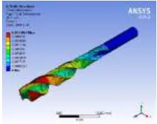
Fig - 8 Deformation in drill bit for HSS.
[image:3.595.107.219.349.438.2]Fig - 9 Equivalent strain in drill bit for HSS.
[image:3.595.377.490.453.542.2]Fig - 10 Equivalent stress in drill bit for HSS.
[image:3.595.104.219.483.571.2]Fig - 11 Deformation in drill bit for alpha titanium alloy.
[image:3.595.377.490.571.661.2] [image:3.595.104.219.596.685.2]© 2019, IRJET | Impact Factor value: 7.34 | ISO 9001:2008 Certified Journal
| Page 197
Fig - 13 Equivalent stress in drill bit for alpha titanium [image:4.595.104.219.333.423.2]alloy.
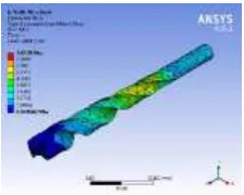
Fig - 14 Deformation in drill bit for beta titanium alloy.
Fig - 15 Equivalent strain in drill bit for beta titanium alloy.
Fig - 16 Equivalent stress in drill bit for beta titanium alloy.
3. RESULT & DISCUSSION
From above analysis we can see that there are total two materials (Alpha titanium alloy and Beta titanium alloy) used for analysis and got the different result with parameter, from that the beta titanium alloy is best of them which comes in the nearby comparison with HSS. Usually drill bits are made from HSS and Cobalt by using forging but we mostly we use HSS as a material for drill bit making. Thus we have used different materials for overall design of drill bit to check the von misses stress and total deformation under same condition of momentum with fix support.
Graph – 1 Comparison between alpha and beta titanium alloys with HSS on the basis of their deformation.
0.00E+00 2.00E-05 4.00E-05 6.00E-05 8.00E-05 1.00E-04
Strain
HSS
Beta
Alpha
Graph – 2 Comparison between alpha and beta titanium alloys with HSS on the basis of their equivalent strain.
7.8 7.82 7.84 7.86 7.88
Stress
HSS
Beta
Alpha
Graph – 3 Comparison between alpha and beta titanium alloys with HSS on the basis of their equivalent stress.
4. CONCLUSIONS
The current research shows the finite element method analysis of twist drill bit made from alpha and beta titanium alloys with HSS material using static structural analysis on ANSYS WORKBENCH 19.2. The boundary conditions assumed as 100 Nm as moment with one end fixed has applied to all materials, whereas the tool geometry is same for all. Finally, it can be concluded that from both the materials, beta titanium alloy is safer than the alpha titanium alloy on comparison with HSS. The resultant values for beta titanium alloy are: maximum equivalent elastic strain is
6.7536e-5 mm/mm and maximum equivalent stress is 7.8258
[image:4.595.105.218.446.536.2] [image:4.595.311.573.451.553.2]© 2019, IRJET | Impact Factor value: 7.34 | ISO 9001:2008 Certified Journal
| Page 198
However, the equivalent stress formation is more for alpha titanium alloy.
6092/SiC/25p-T6 Al MMC is best suitable material if cost is no issue, otherwise Al Alloy 2024-T6 among these four materials is good for connecting rod obtained from this research analysis.
Scope of Future Research: Based on the conducted research, the following areas are recommended for future research:
This thesis has dealt with the reliability and
maintainability analysis of drill bit and future research should focus on greater use of DRILL BIT analysis to enhance its life cycle.
More research is needed on calculation of the cost of
improving the drill bit design in order to obtain the drill bits in a cost-effective way.
Due to competition, the manufacturing company may
need to reduce the price of drill bits. As a consequence, the reliability of its structure will eventually be downgraded.
More research is needed to estimate the optimal
preventive maintenance replacement intervals of the drill bits.
Also, this could give us the addition in the body of
knowledge in the area of drilling with specific context to the selected combinations of work material and tool.
REFERENCES
[1] Yipin Wan, Yongbo Xia, Xuding Song, “Research on
innovation design of the DTH drill based on reverse engineering”, 4th International Conference on Energy Equipment Science and Engineering, 2019.
[2] G. Manoj reddy, D. pinakapani reddy, K. jagadeesh,
M.eswar sai, Y. V. Hanumantha Rao, “Finite Element Stress Analysis of Drill Bit in Ansys”, International Journal of Innovative Technology and Exploring Engineering (IJITEE), Vol. 8 Issue 7, May 2019.
[3] Ruslon Mukanov, Asylbek Kasenov, Galeya Itybayeva,
Zhanara Musina, Guntis Strautmanis, “Modeling of the cutting head for treating holes in the railway”, ICTE in Transportation and Logistics, ScienceDirect, 2018.
[4] Alessandra Caggiano, Luigi Nele and Roberto Teti,
“Drilling of Fiber-Reinforced Composite Materials for Aeronautical Assembly Processes”, CHAPTER 2018.
[5] V Srinivas, “Design and Analysis of drill bit with various
materials using ANSYS”, Journal of Engineering and Applied Sciences, Vol. 13 Issue 6, 2018.
[6] Meenakshi Sundaram Nagaraj, Chakaravarthy
Ezhilarasan, A. John Presin Kumar and Rishab Betala, “Analysis of Multipoint cutting tool temperature using FEM and CFD”, Manufacturing Review 5, 16 , 2018.
[7] J. Santhosh, S. Raja, R. Anandan, “Small Hole Drilling On
Inconel 625 Alloy”, International Journal of Research and Analytical Reviews (IJRAR), Vol. 5 Issue 3, September 2015.
[8] Amardeepak M, Dr. Narayana B Doddapattar, Dr.
Sanjeev Murthy, “Effect of Cutting Parameters on Surface Roughness in Drilling and Tribological Analysis of Aluminium Alloy Al7068”, International Journal of Research and Analytical Reviews (IJRAR), Vol. 5 Issue 4, October 2018.
[9] Ganesh Malayath, Jayachandran KN, Ajay M Sidpara
and Sankha Deb, “Experimental and theoretical investigation into simultaneous deburring of microchannel and cleaning of the cutting tool in micromilling”, Journal of Engineering Manufacture, 5 August 2018.
[10]M S Momeni, S Ridha, S J Hosseini1, B Meyghani and S S
Emamian, “Bit selection using field drilling data and mathematical investigation”, IOP Conference Series: Materials Science and Engineering, 328, 2018.
[11]Ismail Tekaut, Halil Demir, Ulvi Seker, “Experimental
Analysis And Theoretical Modelling Of Cutting Parameters In The Drilling Of AISI H13 Steel With Coated And Uncoated Drills”, Transactions Of Famena XLII-2 , 2018.
[12]Gautam Shankar Tate, Aamir M. Shaikh, Anant
Dattatray Awasare, “Drilling on Glass Fiber Reinforced Composite Material for Enhancement of Drilling Quality: A Review”, International Journal of Engineering Research and Technology, Vol. 10 Number 1 2017.
[13]Pravin Pawar, Raj Ballav, Amaresh Kumar, “Modeling
and Simulation of Drilling Process in Ti-6Al-4V, Al6061 Using Deform-3D Software”, International Journal of ChemTech Research, Vol. 10 No.3, pp 137-142, 2017.
[14]Puneeth H V, Smitha B S, “Studies on Tool Life and
Cutting forces for drilling operation using Uncoated and coated HSS tool”, International Research Journal of Engineering and Technology (IRJET), Volume 4 Issue 6, June - 2017.
[15]A. Attanasio, F. Fainia, J.C. Outeirob, “FEM simulation of
tool wear in drilling”, 16th CIRP Conference on Modelling of Machining Operations, ScienceDirect, 2017.
[16]C. Thomas Vangsness III, Bruce L. Tai, “A feasibility
study of laser-assisted titanium implant drilling for periprosthetic fracture repair”, 3rd CIRP Conference on BioManufacturing, ScienceDirect, 2017.
[17]Rajan. K, Prabhushankar. N, Nagarajan. N, “A Review of
Current Micro Drilling Processes”, International Journal of Innovative Science, Engineering & Technology, Vol. 3 Issue 1, January 2016.
[18]B. Suresh kumar, V. Vijayan, N. Baskar, “Comparison of
coated and uncoated carbide drill bits for drilling titanium grade 2 material”, MECHANIKA. Vol. 22(6): 571 – 575, 2016.
[19]JialinTian, ChuanhongFu, LinYang, ZhiYang,
© 2019, IRJET | Impact Factor value: 7.34 | ISO 9001:2008 Certified Journal
| Page 199
[20]Pravin Pawar, Raj Ballav, Amaresh Kumar, “Finite
Element Method Broach Tool Drilling Analysis Using Explicit Dynamics ANSYS”, International Journal of Modern Manufacturing Technologies, Vol. VIII, 2016.
[21]Tushar Gundarneeya, Hilesh Chaudhari, “Analysis of