BACHELOR THESIS
IMPROVING THE 'ARM
USAGE COACH'
Luuk van Heumen
FACULTY OF ELECTRICAL ENGINEERING, MATHEMATICS AND COMPUTER SCIENCE
BIOMEDICAL SIGNALS AND SYSTEMS
EXAMINATION COMMITTEE
Prof. dr. ir. H.J. Hermens Dr. ir. B.J.F. van Beijnum Prof. dr. D.K.J. Heylen B.Klaassen, MSc.
DOCUMENT NUMBER BSS - 15-19
Page | 1
PREFACE
With this report, I present you with my bachelor assignment. I had the privilege of working with the department of Biomedical Engineering at the University of Twente. The aim of this thesis is to improve upon an existing design of the Arm Usage Coach, a device realized to provide feedback to paretic stroke sufferers on the usage of their affected arm.
During my assignment, I learned about finding shortcomings in existing systems and learning how to combat them. I also learned about 3D modelling and the capabilities of current lines of 3D printers. Finally, I learned how to effectively compare two systems using realistic criteria. All in all, this has been a great learning experience, and I could not have done it without the help of multiple members of staff at the university. As such, I would like to take this opportunity to thank several people.
First and foremost, I would like to thank Bert-Jan van Beijnum, my daily supervisor, for his guidance during the research project and his help in solving several problems I ran into. His guidance helped keeping me on track, and his enthusiasm for the project was palpable. I would like to thank Hermie Hermens, Bart Klaassen and Dirk Heylen for participating in my bachelor assignment committee. Furthermore, I would like to thank Andrea Minuto for his help during the 3D printing process. I would like to thank Ed Droog and Marcel Weusthof for their help with the hardware section of the project. I would also like to extend my thanks to all the people that have helped me during the course of the project by either participating as test subjects or by helping me putting the device together. Last but not least, I would like to thank my friends and family for their help and support, as well as being there to distract me when it became a little overwhelming.
I do sincerely hope you enjoy reading this report. Luuk van Heumen
Page | 2
SUMMARY
Every year, fifteen million people suffer from a stroke worldwide, making it a global problem. [1] One of the more common disabilities that results from stroke is a paresis of half the body. After intense rehabilitation, 50% of stroke survivors can make a functional recovery. However, after a recurrent appointment, it is often concluded that the regained motor function has attenuated. In order to provide on-body feedback to stroke patients, Peter Bartels has developed a system called the "Arm Usage Coach". This system can be used to make stroke patients aware of the fact that they need to keep using their affected limbs. The original system worked fine, but came with some shortcomings.
This report explores an improved design to the Arm Usage Coach, which combats these shortcomings while attempting to retain the basic functionality of the system. Four supporting research questions were composed in order to achieve the main goal.
Firstly, the original system is described and its shortcomings are researched. It was found that the main problems with the system were comfort, size and cost. This was mainly because of the Components of the Shelf nature of the system.
In order to retain the functionality of the system, two BITalino toolkits are used to track arm movement(s) of the patient. This data is sent to a personal computer running MATLAB, which
performs calculations on these movements. Feedback is given through a LilyPad arduino Vibe Board, which is connected to one of the BITalino toolkits.
Page | 3
SAMENVATTING
Elk jaar zijn er zo'n vijftien miljoen mensen wereldwijd die een beroerte krijgen. [1] Een
veelvoorkomende fysieke handicap die optreedt na een beroerte is hemiparesis, een verzwakking van de helft van het lichaam. Na intensieve fysieke therapie kan het meerendeel weer hun aangedane lichaamszijde effectief gebruiken. Bij een later terug-kom-moment blijkt echter dat de functies die via de therapie behaald zijn, weer zijn verzwakt. Om on-body feedback te geven aan mensen die een beroerte hebben gehad, heeft Peter Bartels een systeem ontwikkeld genaamd de "Arm Usage Coach". Dit systeem kan worden gebruikt om gebruikers er bewust van te maken dat ze hun
aangedane zijde moeten blijven gebruiken. Dit originele systeem werkt prima, maar kwam met enkele tekortkomingen.
Dit verslag onderzoekt een vernieuwd ontwerp van de Arm Usage Coach, welke poogt deze
tekortkomingen aan te pakken. De functionaliteit van het systeem blijft echter wel behouden. Om dit doel te bereiken zijn vier ondersteunende onderzoeksvragen opgesteld.
Allereerst wordt het originele systeem beschreven en de tekortkomingen worden aan het licht gebracht. Gevonden werd dat de voornaamste problemen van het systeem zijn comfort, kosten en grootte waren. Dit valt voornamelijk te wijten aan het "Component of the Shelf" idee achter het systeem.
Om de functionaliteit te behouden, worden twee BITalino toolkits gebruikt om bewegingen van de arm van de gebruiker te meten. Deze data wordt naar een windows pc gestuurd waar MATLAB op runt, welke deze data verwerkt en er berekeningen op uitvoert. Indien nodig wordt feedback gegeven via een LilyPad Arduino Vibe Board, welke verbonden is aan een van de BITalino toolkits.
Vier verschillende container designs worden ontwikkeld en getest aan de hand van acht gezonde proefpersonen. Uit deze evaluatie komt een design rollen, wat uitgebreid wordt en als basis zal dienen voor de Arm Usage Coach v2.
Page | 4
Contents
Introduction ... 6
1.1 Motivation ... 6
1.2 Main goal and research questions... 7
1.3 Report structure ... 7
2
Current design ... 9
2.1 Description of current design ... 9
2.2 Review and evaluation of design choices ... 10
2.2.1
Track arm movement(s) - Xsens MtW sensors ... 11
2.2.2
Translate raw data into movement data - Difference Acceleration Vectors (DAVs) .... 11
2.2.3
Implement decision criteria - Therapist enters values ... 11
2.2.4
Transform to system comprehensible data - Duration arm movements... 11
2.2.5
Actuate tactors - Elitac ... 12
2.3 Shortcomings of the current system ... 12
3
Concept development ... 13
3.1 Hardware and Electrical components ... 13
3.2 Physical design ... 13
3.2.1
Concept 1 - "The Watch" ... 14
3.2.2
Concept 2 - "The Bracelet" ... 14
3.2.3
Concept 3 - The Mobile Bracelet ... 15
3.2.4
Concept 4 - The Blocks ... 15
3.3 Logic ... 16
4
Usability Evaluation of the wristband designs ... 18
4.1 Methodology ... 18
4.2 Results ... 19
4.3 Discussion ... 20
4.4 Conclusion ... 20
5
Evaluation final design... 22
5.1 Methodology ... 22
5.2 Results ... 23
5.3 Discussion ... 24
6
Discussion ... 26
6.1 Discussion ... 26
6.2 Conclusion ... 27
6.3 Future research ... 28
Appendix A. Activities of Daily Living (ADL) protocol ... 30
Page | 5
Connectors ... 31
Engine 1 ... 31
Engine 2 ... 33
Engine 3 ... 35
Transfer function ... 37
Appendix C - System Usability Scale Questionnaire ... 38
Appendix D - Computer System Usability Questionnaire ... 39
Appendix E - Information Provided to Participants Final Evaluation ... 40
Appendix F - Revised Matlab code ... 41
Engine 1 ... 41
Engine 2 ... 43
Page | 6
INTRODUCTION
In this introduction a short motivation will be put forward. Additionally, a brief description of what a stroke entails will be given. The main research problem will be defined, as well as the sub-problems that are to be addressed in order to find a solution to the problem. Lastly, the structure of this report will be outlined.
1.1 Motivation
According to the World Health Organization (WHO), about 15 million people suffer from a stroke every year [1]. Of those, 5 million people die and another 5 million are left permanently disabled. Stroke is a global problem, there are very few countries where stroke isn't a prevalent cause of death. From China (1.6 million deaths in 2002) to the U.S. (130.000 deaths each year) [1, 2].
On January 1st, approximately 174.400 people had suffered from a stroke in the Netherlands, with the prevalence being slightly higher for males (1,1%) than for females (0,9%).[3] In 2011, about 26.200 new stroke sufferers were reported in the Netherlands. In 2012, 8.524 people died as a result of stroke in the Netherlands [3, 4].
The WHO defines stroke as:
"The clinical syndrome of rapid onset of focal (or global, as in subarachnoid haemorrhage) cerebral deficit, lasting more than 24 h or leading to death, with no apparent cause other than a vascular one."[5]
Both the WHO and the American National Institutes of Health (NIH) define the underlying mechanism of stroke as the interruption of oxygen-rich blood to the brain, resulting in death of brain tissue [6, 7]. This interruption can be caused by embolisms, thrombosis or some other vascular disorder. Should a stroke occur due to a blockage in blood vessels, it is considered an ischemic stroke [8]. About 85-90% of all strokes are ischemic in nature, the other 15% are hemorrhagic strokes, where the interruption is caused by bleeding. Of the two, hemorrhagic strokes are the most lethal (37,5% mortality within 30 days). A certain type of hemorrhagic stroke called subarachnoid hemorrhagic stroke is the least prevalent, with only 7% of all strokes being SAH strokes, but it has a 50% mortality rate [9].
A common complication that results from a stroke is hemiparesis, which is a weakness on one side of the body [10]. (Hemi)paresis is one of the most common disorders exhibited by patients after damage to the central nervous system [11, 12]. The more severe form is called hemiplagia, which is a complete paralysis of a single side of the body. Paretic movements in general are slower, less accurate and less efficient than movements performed by a person with a fully functioning nervous system [11].
Different studies suggest that at most 50% of patients with significant arm paresis make a useful recovery [13]. Duncan et al. have shown that the Fugl-Meyer score at 30 days is a good indicator for the recovery of motor function within the first six months [12, 14].
Post stroke, survivors usually go through intensive rehabilitation in order to make sure that they recover and retain as much motor function is the paretic limb as possible. Important to note is that the aim of rehabilitation is recovery, and not compensation. Meaning that it is found important that the patient keeps using the afflicted limb instead of allowing the not afflicted body part to take over major motor functions. During a recurrent appointment, several months post-rehabilitation, therapists often found that the level of capacity reached through intensive rehabilitation has not been retained. Because of this decline, the desire came about to investigate how patients behave at home, away from the watchful eyes of the rehabilitator. This is the starting point for the INTERACTION project [15]. The objective of the INTERACTION project is to develop and validate an unobtrusive and modular system for monitoring daily life activities and for training of upper and lower extremity motor function in stroke subjects[16].
Page | 7 This system, while looking promising with healthy subjects, came with a few downsides however, like the cost, its size and the perceived comfort. The system will be described in greater detail in chapter 2.
1.2 Main goal and research questions
The current prototype was built from components off the shelf (CotS). Because of this CotS nature, the design choices were limited. As such, the current design has a few shortcomings, which became prevalent during the usability studies performed by Peter Bartels. [15] Among these are its size and comfort. To make the system more appealing to insurance companies and distributors, the cost needs to be severely lowered as well. In this research project a new and improved design shall be presented. The main goal of this research project can be defined as follows:
" The development of a new design of the 'Arm Usage Coach', which improves upon comfort, size and cost while keeping the main functions intact. "
This Arm Usage Coach can be used by stroke patients during Activities of Daily Life (ADL) and will help the subjects to sufficiently use the affected limb and extremities. In this context, "sufficiently" is a subjective term which differs from patient to patient.
In order to achieve the primary goal of the research project, a few more research questions have to be answered beforehand. The first of these is:
"What is the current design for the Arm Usage Coach and what are its shortcomings?"
The current design will be described and the decisions made during the design process will be looked at. Using the results from the usability study, shortcomings of the device can be determined. After the shortcomings of the current system have been determined, the next question can be stated:
"What are possible solutions to overcome these shortcomings and how can they be implemented?"
In order to find solutions to overcome the shortcomings, research will have to be done on different devices that can perform the same functions as the current Arm Usage coach. These devices will have to be compared and a choice has to be made for one of them. The chosen hardware will have to be mounted onto a device of some sort. Multiple designs for this device will be drawn up and explained. The next question will be which of the designs is the best. As such, the next research question can be formulated:
"Which of the proposed designs is best suited to combat the shortcomings?"
In order to find out which design is the most user friendly, all designs will be prototyped and evaluated by means of a student panel. From this evaluation, a final design can be chosen and developed further. Once this prototype has been developed, the final research question can be answered:
"How does the new prototype compare to the existing Arm Usage Coach?"
The new prototype will be compared to the existing design by evaluating it using the exact same methods used to evaluate the existing Arm Usage Coach and comparing the results of the evaluations.
1.3 Report structure
In this first chapter, a motivation and a brief description of stroke have been presented, as well as a set of research questions that have to be answered before the primary goal of this project can be achieved. In chapter 2 the current design will be described, and the design choices made for it will be examined and evaluated. Its shortcomings will be presented at the end of the chapter.
Page | 8 Chapter 4 will contain an evaluation on the user friendliness of the different designs proposed in
chapter 3. The evaluation will be performed with the help of a panel of volunteers. A final choice for the new design will be made, to be tested and evaluated in chapter 5, among other ways by comparing it to the current design and seeing how it holds up.
Page | 9
2
CURRENT DESIGN
This chapter contains the current Arm Usage Coach, as designed by Peter Bartels, as well as all the choices made during the design process. These choices will be reviewed and evaluated. At the end of the chapter, the shortcomings of the current design will be presented
2.1 Description of current design
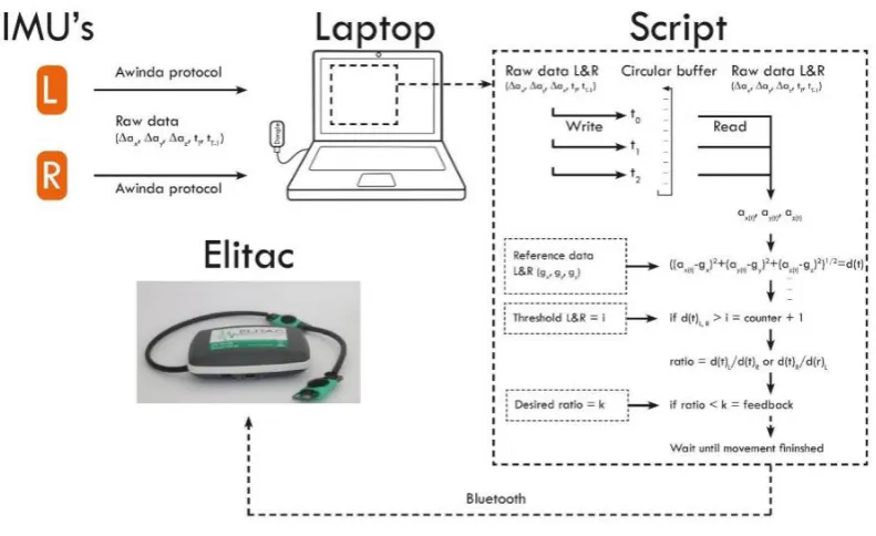
The current design is shown in Figure 1, it consists of a set of two Velcro wristbands, which both hold an Xsens MtW Inertial Measurement Unit. To provide feedback, an Elitac Tactile Display Controle Module has been used. The logic for the system was written in MATLAB and runs in the background during measurements [15]. A customized script is used to ensure real-time data streaming from the IMUs to MATLAB. The system determines movement based on the Difference Acceleration Vectors (DAVs). Before any measuring occurs, the threshold for what constitutes a movement has to be determined, as well as the desired ratio between usage of the afflicted and non-afflicted arm.
[image:10.595.72.385.320.564.2]The triaxial accelerometer data from the IMUs is logged and stored in a 20 Hz circular buffer, which is to be used during the data translation and feedback processes [15].
FIGURE 1 - CURRENT DESIGN, ADAPTED FROM [15] WITH PERMISSION.
When the system is booted, the user is prompted to stand in the n-pose in order to calibrate. This calibration is used in the calculation of the length of the DAVs. Upon user movement, the
accelerometer data is logged in a circular buffer, after which the system reads this data in one-second intervals from the buffer. The length of the DAV is calculated, using the formula which is presented further on in this chapter. If the DAV length is above a previously chosen threshold, the system will consider the arm to be moving and will start logging the movement. As soon as the DAV length falls below the threshold, the system will consider the movement to have finished. Data will be measured from both IMUs simultaneously. [15].
Page | 10 FIGURE 2 - GRAPHICAL REPRESENTATION CURRENT SYSTEM, ADAPTED FROM [15] WITH PERMISSION.
In order to get an idea of what the system had to be capable of, a functional analysis was performed. The functional requirements are shown below in Table 1.
TABLE 1 - FUNCTIONAL REQUIREMENTS CURRENT SYSTEM
Functional requirements Formulated because...
Track arm movement(s) Movements must be detected.
Translate raw data to movement data A variable for the amount of movement per arm must be given.
Implement decision criteria It enables the patient/therapist to change the frequency to improve the patients condition. Transform movement data to system
comprehensible data
Movements must be detected by the system. Manage personal feedback preference Each patient has their own preference when it
comes to feedback.
Actuate tactor(s) Feedback must be provided when necessary. Store Data Present history data to therapist and patient. Present history data to patient Instrinsically motivate/create awareness for the
patient.
Present history data to therapist Inform about the patients performance. This concludes the general description of the current prototype. In the next part, the design choices made by Peter Bartels will be reviewed and evaluated.
2.2 Review and evaluation of design choices
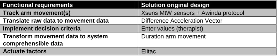
[image:11.595.63.529.376.564.2]Page | 11 TABLE 2 - DESIGN CHOICES CURRENT SYSTEM
Functional requirements Solution original design
Track arm movement(s) Xsens MtW sensors + Awinda protocol Translate raw data to movement data Difference Acceleration Vector
Implement decision criteria Enter values (therapist) Transform movement data to system
comprehensible data
Duration arm movement
Actuate tactors Elitac
2.2.1 Track arm movement(s) - Xsens MtW sensors
The sensors used for tracking the arm movements are Xsens MtW sensors. These sensors measure 3D acceleration, as well as 3D orientation, 3D rate of turn, 3D earth magnetic field and static pressure, all of which can be considered superfluous for the design at hand. As such, they are rather sizable components (34.5 x 57.8 x 14.5 mm), even more so compared to commercially available
accelerometers, which can be as small as 3 x 3 x 1 mm. Even taking into account the need for a processor and battery, most commercially available hardware is smaller than the MtW sensors. The sensors require a secondary system to work (for example, a personal computer running dedicated Xsens software). This limits the range in which the system can be used to about 10 meters around a central system. Furthermore, the components are very expensive, with prices ranging to over €3000 as of May 2015. These qualities. while acceptable for lab trials, make the system too expensive, bulky and short-ranged for home use.
2.2.2 Translate raw data into movement data - Difference Acceleration Vectors (DAVs)
The current system uses a metric called the Difference Acceleration Vector (DAV). This unit compares the average acceleration over a period of one second to a previously calibrated reference value. The formula for the DAV is as follows:
At first, there was some apprehension on continuing to use this, relatively new, method of measuring. However, upon further examination, and using data from actual stroke patients obtained through the INTERACTION project, it was found that the DAV, when calibrated properly, was a good indicator for movement during ADLs.
2.2.3 Implement decision criteria - Therapist enters values
The decision criteria consist of the threshold for movement, and the ratio that needs to be met. Among the solutions proposed by Bartels was a self-learning system that can implement these decision criteria based on how the user performs on a day to day basis. This is a good end goal to work towards before the system becomes available for consumers. In the systems current state however, the therapist is the better choice for entering values that they find correspond to the patient's abilities.
2.2.4 Transform to system comprehensible data - Duration arm movements
Page | 12 2.2.5 Actuate tactors - Elitac
To actuate the tactors, an Elitac Tactile Display Controle Module was used in the first design. The Elitac is a Bluetooth connected control module with added tactors. Much like the Xsens MtW IMUs, the Elitac control module is very bulky (75 x 45 x 20), as well as very expensive (<€2000 as of May 2015). The control module is dependent on a personal computer to tell it to actuate the vibration units, which limits the freedom of the patient during the utilization of the device. These qualities make the Elitac a good candidate for lab trials and R&D applications. In order to make the system more suitable for home use, the cost and size will have to be lowered, the former rather significantly.
2.3 Shortcomings of the current system
The shortcomings of the current system, which have been touched on in chapter 2.2, will be restated here. The current design has a few shortcomings, mainly when it comes to:
Size, the system components are bulky and restrict movement when performing certain actions.
Comfort, multiple subjects noted the system was rather uncomfortable to wear.
Cost, the system is at the moment too expensive to be made widely available for home use.
Dependency, the system is dependent on a secondary "master", a personal computer running the engines.
Page | 13
3
CONCEPT DEVELOPMENT
Now that the shortcomings of the current design have been presented, it is possible to look for solutions to these problems. The main factors preventing the current design being viable as a revalidation tool for home use are its size and comfort, as found in usability studies done on the current design. [15] Another factor that prevents the design from being wide-spread as a home revalidation tool is its cost. This chapter will go over the different concepts with regard to the hardware that's to be used, as well as the container that should house the device.
3.1 Hardware and Electrical components
The device needs to be able to read data from an accelerometer, implement decision criteria, as well as provide feedback to the user in case the decision criteria aren't met. It is possible to use an arduino kit such as the LilyPad arduino kit. This arduino can be sewn onto clothing and connected by means of conductive thread. The problem with the LilyPad arduino is that the controller is rather sizeable and the system has no innate Bluetooth module. Furthermore, because the measurements will be confined to the system, debugging and looking for errors in the measurements will be very time-consuming. Add to that programming in an unfamiliar programming language (C++), and the LilyPad is looking less and less promising.
An alternative would be to use an android phone. In theory, this could do anything the current system does and do it reliably. However, android phones are sizable and rather expensive, so it wouldn't solve the main shortcomings of the current design. Having never programmed for android devices, the idea of using an android based platform such as a smartphone or smartwatch was quickly discarded. In order to lower the cost as well as size of the device, the choice was eventually made to use the BITalino toolkit (Plux, Portugal). This low-cost toolkit comes with a triaxal accelerometer and Bluetooth I/O module, as well as a power supply block and a small, reprogrammable micro-controller unit (MCU). It is relatively small, with the MCU (41x20x3) and the standard 700 mAh battery (30x32x5) being the largest components by far. The latter is replaced by a Turnigy 260 mAh battery in the new design. In order to provide feedback, the choice was made to use the LilyPad arduino vibe board, which can be connected to the BITalino MCU and controlled remotely. Another aspect of the BITalino toolkit that makes it very useful, is the number of different APIs that are available. Using this same sensor kit, the logic could in theory be run on a smartphone or other small device.
3.2 Physical design
Now that the choice has been made for the BITalino toolkit, the need for a physical design to house all the components has arisen. Because the system has to measure movements from the arm, it was decided to create a wristband to contain the hardware. This wristband should be able to house the following components:
BITalino Micro-Controller Unit (MCU) (41x20x3)
BITalino Power Supply Unit (PSU) (20x30x3)
BITalino Bluetooth Module (BT) (20x31x3)
BITalino Accelerometer (ACC) (18x16x3)
Turnigy 260 mAh LiPo battery (BATT) (32x20x7)
Page | 14 As well as the following electronic connections:
Connections between the MCU and the PSU (6 wires)
Connections between the MCU and the BT (6 wires)
Connections between the MCU and the ACC (5 wires)
Connections between the MCU and the VB (2 wires)
Connections between the BATT and the PSU (2 wires)
After consultation with several people and some brainstorming, four basic ideas for concepts were conceived. The following ideas served as a basis for the development of the different concepts:
1. All components are placed in a single rigid container. 2. All components are mounted on a rigid structure.
3. All components are mounted on a semi-rigid structure. The structure can move slightly using joints.
4. All components are mounted on multiple, flexibly interconnected structures. These ideas are expanded into full concepts, which are described in turn in the next part.
3.2.1 Concept 1 - "The Watch"
The first concept for the physical design was a single, square container. Figure 3 shows a photo of the design, which was printed using an Ultimaker2 Extended 3D printer. Figure 4 shows the original 3D model, realized in SolidWorks. The design can be worn around the wrist, akin to a watch, using an elastic band which can be run through the back of the design.
All of the components will be contained within the watch, so damage from external sources becomes less likely. In order to fix all of the components in place, some non-conductive adhesive should be used.
FIGURE 3 - PHOTOGRAPH OF THE WATCH FIGURE 4 - 3D MODEL OF THE WATCH
3.2.2 Concept 2 - "The Bracelet"
The second concept was created in order to make the device a bit easier to carry around. It consists of a single, solid bracelet with embossments made to socket the components. Figure 5 shows a
Page | 15 FIGURE 5 - PHOTOGRAPH OF THE BRACELET FIGURE 6 - 3D MODEL OF THE BRACELET
3.2.3 Concept 3 - The Mobile Bracelet
[image:16.595.73.473.408.522.2]Design concept 3, a photograph of which is shown in Figure 7 and a 3D model in Figure 8, is an adjustment to design concept 2. It aims to regain the idea of being able to fit multiple wrist sizes. In order to adjust for larger size changes, two different versions will be developed, both capable of housing all the components. One version will be for smaller to average sized wrists, and the other for larger wrists. For prototyping, only the version that fits slightly larger wrists will be printed and tested. In this design, the circuitry will be located in the same place as in design 2. This means it will bring with it the same pros and cons from that design. The main difference will be ease and relative comfort of carrying, which will have to be evaluated using a panel of students.
FIGURE 7 - PHOTOGRAPH OF THE MOBILE BRACELET FIGURE 8 - 3D MODEL OF THE MOBILE BRACELET
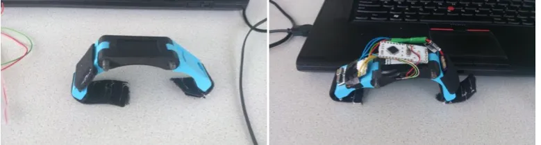
3.2.4 Concept 4 - The Blocks
The basic idea behind concept 4 is to mount all the components in separate blocks, with the wiring connecting the components running through fabric or heat shrink tubing connections. A photograph of design concept 4 is shown in Figure 9 and a 3D model in Figure 10. This design aimed to improve the comfort of wearing the device, by splitting it up into several smaller parts. This is achieved by placing the components in several blocks, as shown in Figure 10. The distribution of components is as follows, considering three 'blocks':
Centre block: MCU, BT Module and Accelerometer
First side block: PSU
Second side block: Battery
Page | 16 FIGURE 9 - PHOTOGRAPH OF THE BLOCKS FIGURE 10 3D MODEL OF THE BLOCKS
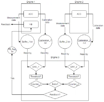
3.3 Logic
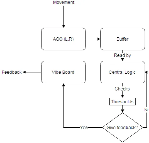
The logic that the system requires is shown in its most basic form in Figure 11.
FIGURE 11 - BASIC ARCHITECTURE OF THE LOGIC NEEDED
This basic architecture is mostly the same as that of the original design. The main focus of this research is to develop a new design and test out different hardware. The underlying logic, as created by Peter Bartels, works properly. As such, it was decided to mostly recycle the architecture of the logic.
[image:17.595.74.313.323.553.2]Page | 17 To recap, the new design will consist of one out of four possible physical designs, with a BITalino toolkit worked into it. The choice for the physical design will be made and explained in the next chapter. For the logic, a laptop or tablet capable of running multiple instances of MATLAB will be used to read data from the devices, store it in a circular buffer and apply decision criteria set beforehand. The MATLAB code will be split between three engines in the following fashion:
1. Engine 1: Connects to and reads data from the wristband without the vibe board, data is stored in a circular buffer.
2. Engine 2: Connects to and reads data from the wristband with the vibe board, data is stored in a circular buffer. Will actuate the vibe board if deemed necessary by the Logic
Page | 18
4
USABILITY EVALUATION OF THE WRISTBAND
DESIGNS
In this chapter, a choice will be made for one of the wristband designs proposed in chapter 3. First, the methodology will be described and the protocol used will be presented. Afterwards, the results will be given. Finally, these results will be discussed and a final design will be chosen.
4.1 Methodology
In order to evaluate the wristband designs, a panel of 8 students, 4 male and 4 female, were asked to participate in a study.
The subjects were presented with the wristbands and had the protocol explained to them. They were asked to perform a specific set of movements, which correspond to ADL-tasks a stroke patient might perform. The full set of movements is as follows:
1. Sit behind a desk
2. Get up from the desk and walk to the door 3. Open the door, walk through it
4. Walk to a table
5. Pick up and object from the table and place it down again 6. Walk back through the door and close it behind you 7. Reach for an item on a shelf
8. Place the item back
9. Take a seat behind the desk 10. Scribble on a notepad 11. Browse through a book
The participants were asked to perform this set of movements 4 times, after which they were asked to rank the wristband designs from best to worst in the following categories: aesthetics, comfort and intrusiveness. The results were noted and analysed using MS Excel. The final score calculation was performed as follows:
For both the intrusiveness and comfort score, the points assigned were calculated by subtracting the rank from 5, yielding a score between 1 and 4.
For the aesthetics score, the points assigned were calculated by subtracting the rank from 5 and then dividing the answer by 2, yielding a score between 0.5 and 2. This was done because the aesthetics of the wristband design is not as important as the other two scores, but it does count for something still. Adding all of the scores together yields a final grade between 2.5 and 10, with 10 being the highest score attainable.
Page | 19 4.2 Results
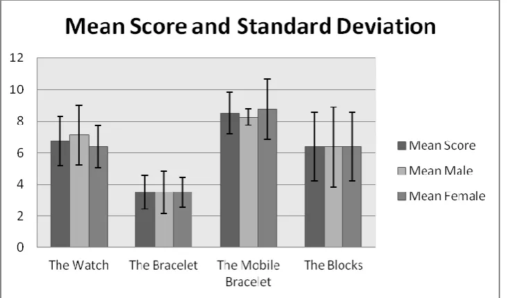
[image:20.595.73.439.144.359.2]The results of the first evaluation is shown in Figure 12, with the average score per subject presented in Table 3. Of the four concepts, "The Mobile Bracelet" scored the highest with both male and female participants.
FIGURE 12 - MEAN SCORES USER FRIENDLINESS TEST, TOTAL MEAN AND BASED ON MEAN CALCULATED BASED ON GENDER
TABLE 3 - SCORES USER FRIENDLINESS TEST
Score Type Watch Bracelet Mobile Bracelet
Blocks
Comfort Score 22 10 26 22
Aesthetics Score 6 8 16 10
Intrusiveness Score 26 10 26 19
Total Score 54 28 68 51
Mean Score 6.75 3.5 8.5 6.38
From these results it's clear that Concept 3 was the winner across the board. Surprising was that concept 1 scored high in the intrusiveness category, which means the participants found it to be very much unobtrusive. Indeed the participants noted not having much trouble with any tasks while wearing the concept. The caveat with this statement, as a few participants themselves had stated, was that the protocol didn't involve grabbing anything from tight spaces, such as dressers or shelves. In these cases, the sheer bulk of the concept would give some problems.
The participants were asked for their opinions on the concepts. Some noted that concept 2 was too bulky, which interfered with the part of the protocol that was done while sat down. Other things that became clear were that many people preferred a Velcro wristband over an elastic one, and that concept 3's main selling point was its slim design.
The second evaluation was about the ideal location and protocol for the vibrotactile feedback. The panel of students all but unanimously said they had no preference on either the location of the tactor or the protocol used during feedback.
[image:20.595.66.532.407.501.2]Page | 20 The students did not show any preference concerning the feedback protocol either. Because
programming this is rather easy, it was decided to not focus on this too much. The final code can easily be changed to provide either continuous feedback or feedback in bursts. The MATLAB code used to control the device can be found in Appendix B.
4.3 Discussion
Now that the evaluations are complete, it is possible to reflect on them. In order to decrease the standard deviations and make for a more accurate result on the first evaluation, more people could be asked to participate in the study. The gender balance was good, but maybe the tests could be done with a group of people other than students. Doing this could give a good idea whether a preference exists based on e.g. age.
The second evaluation was not needed as much as was initially thought, the majority of the
participants stated they have no preference on where the tactor is placed or which feedback algorithm is used. In the end, the placement of the tactor was decided after consultation with different people and the feedback algorithm can be changed at will by altering 4 lines of code.
4.4 Conclusion
From the evaluation it is easy to conclude that "The Mobile Bracelet" was the most user-friendly of the wristband concepts. Several comments that were put forward during the evaluation were taken into account, such as the preference for a Velcro wristband over the elastic band used during the tests. Due to the popularity of the slim design, the design was changed slightly from the original idea presented in chapter 3. The battery is now placed on one of the arms, and the Bluetooth module is mounted directly underneath the MCU. The tactor was embedded in the wristband slightly below the accelerometer, which was socketed in the middle portion of the wristband.
[image:21.595.72.462.468.573.2]All of the soldering was done manually, following a guide on the BITalino website. The final design was 3D printed using an Ultimaker2 and an Ultimaker2 Extended. Both 3D printers are equal in all but height, with the Extended being taller.
FIGURE 13 - FINAL DESIGN WITHOUT COMPONENTS FIGURE 14 - FINAL DESIGN WITH COMPONENTS IN PLACE
Page | 22
5
EVALUATION FINAL DESIGN
This chapter discusses the evaluation of the selected design - as described in chapter 4 - and compares the results to that of the initial design proposed by Peter Bartels. [15]. Firstly, the methodology is explained and the protocols and questionnaires will be presented. Afterwards, the results will be given and compared to those of the original Arm Usage Coach. The results will then be discussed.
5.1 Methodology
In order to evaluate the selected design, 5 healthy subjects have participated in the evaluation of the new Arm Usage Coach version 2. Of these subjects, 2 were left-handed, 2 were right-handed and 1 person was ambidextrous. Because this design is still in the earlier stages of development, the evaluation will only be performed with healthy subjects.
Subjects were asked to put on the wristbands. The first two MATLAB engines were started and used to connect to the BITalino devices. After the connection was made, the participants were asked to stand in the N-pose for 10 seconds, during which calibration took place. Afterwards, a third MATLAB engine was started which ran the application logic, deciding whether or not to give feedback. In order to set the threshold for what constitutes a movement, the participants were asked to do the following:
Walk a short distance as they would normally walk
Walk the same distance, this time moving their arms as if they were reaching for items on tables or shelves
Once the data from these two walks was logged, a threshold could be set by comparing the movement data of the both walks. This way, personalized settings of the application were realised.
When the entire system is running, the participants were asked to perform a specific set of movements, which correspond to ADL-activities. This list differs from the protocol used by Peter Bartels. It incorporates movement that brings the arms slightly higher, in movements 7 and 8. This was done to increase the range of movements that the system is tested with, something Bartels said would lead to a better understanding of the system and its limitations. [15]
The full list of movements is as follows. 1. Sit behind a desk
2. Get up from the desk and walk to the door 3. Open the door, walk through it.
4. Walk to a table
5. Pick up an object from the table and place it down again 6. Walk back through the door and close it
7. Reach for an item on a shelf 8. Place the item back
9. Take a seat behind the desk 10. Scribble on a notepad 11. Browse through a book
Page | 23 After performing the set of movements twice, the participants' were asked to evaluate the design using the System Usability Scale (SUS) and the Computer System Usability Questionnaire (CSUQ). These questionnaires were chosen in order to properly compare the new design to the old system, which was evaluated using these questionnaires. Both of these questionnaires are included in Appendices C and D. The results from these questionnaires are analysed using MS Excel to determine the outcomes of the experiment. All participants were informed of their ability to stop the test at any given time, with no explanation being necessary. The information provided to the participants can be found in Appendix E.
5.2 Results
The results of the SUS and CSUQ of the original design and the final new design are shown side by side in Tables 4 and 5. Results per question can be found in Tables 6 and 7. The new system scores a mean of 73 at the SUS (scored on a scale from 0 to 100) and a mean of 5.0 at the CSUQ (scored on a scale from 0 to 7).
TABLE 4 - SYSTEM USABILITY SCALE QUESTIONNAIRE MEAN AND STANDARD DEVIATION SCORES (5 SUBJECTS) OLD VS NEW DESIGN
Score of SUS Mean original σ original Mean new σ new
Overall 75.0 7.2 73.0 12.5
TABLE 5 - COMPUTER SYSTEM USABILITY QUESTIONNAIRE MEAN AND STANDARD DEVIATION SCORES (5 SUBJECTS, INTERVAL SCALE 7) OLD VS NEW DESIGN
Score of CSUQ Mean original σ original Mean new σ new
[image:24.595.68.502.363.561.2]Overall 5.5 0.8 5.0 1.2
TABLE 6 - SUS SCORES PER QUESTION ARM USAGE COACH V2
SUS Question Mean σ
1 - I think I would like to use this system frequently. 3.4 0.9 2 - I found the system unnecessarily complex. 2 1 3 - I thought that the system was easy to use. 4.2 1.3 4 - I think I would need the support of a technical person to be able
to use this system.
1.6 0.5 5 - I found the various functions in this system were well integrated. 3.2 0.8 6 - I thought there was too much inconsistency in the system. 2.8 0.4 7 - I would imagine that most people would learn to use this system
very quickly.
4.4 1.3
8 - I found the system cumbersome to use. 2 1.2
9 - I felt confident using the system. 4 0.7
10 - I needed to learn a lot of things before I could get going with this system.
1.6 1.3
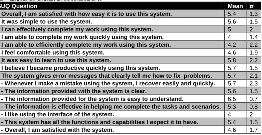
Page | 24 TABLE 7 - CSUQ SCORES PER QUESTION ARM USAGE COACH V2
CSUQ Question Mean σ
1 - Overall, I am satisfied with how easy it is to use this system. 5.4 1.3
2 - It was simple to use the system. 5.6 1.5
3 - I can effectively complete my work using this system. 5 2 4 - I am able to complete my work quickly using this system. 4 1.4 5 - I am able to efficiently complete my work using this system. 4.2 2.2
6 - I feel comfortable using this system. 4.6 1.9
7 - It was easy to learn to use this system. 5.8 2.2
8 - I believe I became productive quickly using this system. 5.7 1.5 9 - The system gives error messages that clearly tell me how to fix problems. 5.7 2.1 10 - Whenever I make a mistake using the system, I recover easily and quickly. 5.7 2.3 11 - The information provided with the system is clear. 5.6 1.5 13 - The information provided for the system is easy to understand. 6.5 0.7 14 - The information is effective in helping me complete the tasks and scenarios. 5.3 0.8
17 - I like using the interface of the system. 4 2
18 - This system has all the functions and capabilities I expect it to have. 5.4 1.5
19 - Overall, I am satisfied with the system. 4.6 1.7
Three statements (12,15,16) from the CSUQ were not included the results, because the majority of the subjects, 3 out of 5, found these statements were not applicable for this system. Statement 5 of the CSUQ reads 'I am able to efficiently complete my work using this system'. The STD was 2.2 on a score of 4.2 out of 7. Subjects found the system to be uncomfortable while performing the final tasks from the movement set.
Statement 7 of the CSUQ is as follows: 'It was easy to learn to use this system'. Some participants noted that running all the MATLAB engines and scripts can be daunting to someone who has no experience using MATLAB. For the other statements with high STDs, the STD becomes higher because not all participants found the statement applicable to the system.
The CSUQ made it possible for participants to state both positive and negative aspects of the design. Participants differed in opinion about the ease of use, both stating that the system was easy to use and not very user-friendly because of its design. Furthermore, the participants found the system slightly uncomfortable to wear, either because of the size or how tightly the wristband has to be in order for the system to not move around. A single participant noted he found the connection loss to be slightly annoying. This can be blamed on a subpar soldering job on one of the wires connecting the MCU and the BT module, where moving it in a certain way would make the system lose connection. Some participants found the delay in the system, which was caused by the logic lagging behind on the buffer, to be a negative aspect. Finally, the system was a good way to remind people to use their affected arm, it was easy to wear, not very intrusive and people found the design aesthetically pleasing.
5.3 Discussion
Now that the evaluation is complete, it is possible to reflect on it. The number of participants is rather limited, due to time constraints. By asking more people to participate, a better impression of the system could be achieved. Furthermore, 4 out of 5 participants were students of Biomedical
Technology. Allowing for a more varied group of participants will give a more accurate representation of what the average person's opinions on the system are.
Page | 25 It is wise to, for further testing, allow participants to wear the system for a longer period of time, so they will experience the feedback algorithm more often.
Page | 26
6
DISCUSSION
In this final chapter, a discussion is given in chapter 6.1, after which a conclusion follows in chapter 6.2. Finally, recommendations for future research are presented in chapter 6.3.
6.1 Discussion
Comparing the Arm Usage Coach V2 to the first design made and the discussion points made by Peter Bartels, we can see that the new version offers improvement in several ways. The weight balance, which was noted as being off between both arms in the original design, is more balanced in version 2. This is because the bulky Elitac module has been replaced with a small LilyPad Arduino vibe board. Furthermore, the new design is smaller, lighter and perceived as being more comfortable by participants in the study.
As has been noted in chapter 5, there has been further discussion with one of the participants of the evaluation of the final design. This participant looked at the system through the eyes of the final end-user and made a few comments on the design. They noted that system looks very intimidating with all the wiring exposed. Additionally, the system would be difficult to use for a single user. In order to avoid that in future designs, the system should be concealed more, with the wiring hidden behind an
external case. In the ideal case, the system should be able to work at the press of a few buttons. However, until the system becomes useable for actual use by stroke patients, this shouldn't be top priority.
The new design still suffers from a few shortcomings though. It is still reliant on a secondary unit, a PC running MATLAB. This could be alleviated in the future by only using Arduino devices. In the future, it should be tested whether or not a system of 1 master and 2 slaves could work. In this set-up, the slaves would be the wristbands with the accelerometer and buzzer plugged in, and the master would be a secondary node, maybe integrated into a clothing article like a belt, which processes all the incoming data and decides whether or not to provide feedback. Another possible solution would be to use the Android API that came with the BITalino device and to run the logic off an android device such as a tablet or smartphone.
Furthermore, the hardware should be looked at. During the tests, the connection between the laptop and the BITalino devices would randomly drop, causing the device to become unresponsive. The MATLAB engine, however, would still read from the circular buffer, causing it to loop around on itself and repeating old data. It would be advisable to find a new connection method, or making use of a device with native Bluetooth support. Concerning other apparatuses that could replace the BITalino, it might be worth looking into something called the LightBlue Bean. This Bean is a small Arduino device with a built in accelerometer and Bluetooth Low Energy (BLE) module. It can run off a single cell battery and is only slightly larger than the BITalino's MCU. Being able to condense the entire device into something much smaller would pave the way for an even more user-friendly design. Having a small device also allows for more freedom with the physical design. Something like the new prototype could easily be concealed in a kind of watch. However, stepping away from the BITalino brings with it the need to rewrite the code used to read from the devices.
Page | 27 1. Bitalino_L_Revised:
Removed circular buffer. 2. Bitalino_B_Revised:
Removed circular buffer.
Added switch case to determine feedback algorithm.
Switch case includes default (burst) algorithm. 3. Logic_Revised:
Removed circular buffer.
Added prompt for feedback algorithm
Made the logic wait for the movements of both arms to finish
Streamlined, made the system closer to real-time
These scripts have not been tested yet, but they should remove most problems that had arisen when using the original scripts.
There were a few problems with the physical design, especially for people with smaller wrists. They noted that the wristband was a bit too large still. The majority of the people who had issues with the size were female. This was mainly because, as was explained in chapter 3, only the larger version of "The Mobile Bracelet" was printed for evaluation purposes. When the system is developed further, both versions can be produced.
6.2 Conclusion
The main goal of this thesis was defined as: " The development of a new design of the 'Arm Usage Coach', which improves upon comfort, size and cost while keeping the main functions intact.". In order to achieve this, the Arm Usage Coach v2 was evaluated using the same questionnaires as the original design. The system is developed as described in chapters 3 and 4, and evaluation by healthy subject is done in chapter 5. From the results, we can conclude that the system new system scores slightly lower on both quantitative scales, but users had commented on finding the system nicely designed and not very heavy, making it easy to wear. The Velcro strap caused some discomfort for some users. The first question that was posed was "What is the current design for the Arm Usage Coach and what are its shortcomings?". This question is answered in chapter 2. A description of the design and design choices of the Arm Usage Coach v1 are given and shortcomings are presented. It can be concluded from research done by Peter Bartels that the main shortcomings of the design are comfort, size and cost.
The second question that needed answering in order to achieve the main goal was "What are possible solutions to overcome these shortcomings and how can they be implemented?". Different solutions concerning electronic components and physical designs are given in chapter 3, which are described briefly. A choice has been made for the BITalino toolkit, because of its versatility when it comes to available APIs, as well as its small size and dedicated hardware.
Now that the electronic components and programming language had been selected, the next question concerned the physical design of the wristband, namely "Which of the proposed designs is best suited to combat the shortcomings?". This question is answered in chapter 4, where an evaluation of all four designs is performed using a group of healthy students. From this evaluation, it can be concluded that concept 3, "The Mobile Bracelet", was perceived as being the most user friendly.
Page | 28 If the comments from the participant whose scores were the lowest are taken into account, the v2 could surpass the v1.
TABLE 8 - COMPARISON V1 AND V2
Cost Size
V1 Measurement – Xsens MtW IMUs
€3000,- for a full set, including charging station, multiple IMUs and wireless dongle
34.5 x 57.8 x 14.5 mm per device, 2 in total
V2 Measurement – BITalino HeartBIT toolkit
€80,- Per toolkit, 2 in total All components fit in a 41 x 20 x 26 mm space, 2 in total
V1 Feedback – Elitac <€2000,- for the module 75 x 45 x 20 mm, single device
V2 Feedback – LilyPad Arduino Vibe Board
€8,- 20 x 5 mm
V1 Total ~ €5000,- All components fit in a 75 x 57.8 x
33.5 mm cube, V=145.2 cubic cm
V2 Total €170,- (About €2,- for the
wristband)
All components fit in an 41 x 40 x 31 mm cube, V= 50.84 cubic cm
6.3 Future research
Now that this project has been completed, recommendations for future research are given below. In order to improve the system even further, it needs to become fully wearable. It should not have to rely on a personal computer running MATLAB. Future research could look into translating the MATLAB code written for the BITalino to the android OS for example, making it so the system can be run using a smartphone or a tablet.
Something that has not been touched upon in this thesis is the ability for the system to retain data, so it can provide both the patient and the therapist with accurate data about the patient's performances. This data history could be applied to a self-learning system, which could adjust the desired ratio depending on the patient's performance, ranging from a minimal to a maximum value.
What is still missing and can't be ignored is the need to motivate the patient to keep using the system. There needs to be a bit of interaction between the user and the system. This could be achieved by displaying performance history to the patient, giving them motivation to actually keep their positive streak going or to get out of their decline. In order to appeal to the more competitive nature of some people the performance data could be uploaded to a server, so they can compare themselves against other users. Dividing the users in fair groups would be key though. Most of this is research for later in the future though.
For now, the main focus should be condensing the system down even further. Make it smaller, make it fully wearable, independent of any other stationary components.
Page | 29 References
1. Mensah, G., Mackaj, J., The Atlas of Heart Disease and Stroke, ed. W.H. Organization. 2004, Geneva: WHO.
2. CDC, N., Underlying Cause of Death 1999-2013 on CDC WONDER Online Database. 2015. 3. RVM - Ministerie van Volksgezondheid, W.e.S. Hoe vaak komt een beroerte voor en hoeveel
mensen sterven eraan? 2014 June 23, 2014 [cited 2015 Apr 28]; 4.17:[Available from:
http://www.nationaalkompas.nl/gezondheid-en-ziekte/ziekten-en-aandoeningen/hartvaatstelsel/beroerte/omvang/.
4. Hartstichting, Hart- en vaatziekten in Nederland 2013. 2013, Papendrecht: Mouthaan Grafisch Bedrijf.
5. Warlow, C., et al., Stroke. The Lancet, 2003. 362(9391): p. 1211-1224.
6. Services, U.S.D.o.H.a.H. What Is a Stroke? - NHLBI, NIH. 2014; Available from: http://www.nhlbi.nih.gov/health/health-topics/topics/stroke.
7. WHO. WHO | Stroke, Cerebrovascular accident. 2015 [cited 2015 Apr 28]; Available from: http://www.who.int/topics/cerebrovascular_accident/en/.
8. Muir, K.W., Stroke. Medicine, 2009. 37(2): p. 109-114.
9. University Hospital Newark, N. Stroke Statistics - University Hospital. 2013 [cited 2015 Apr 28]; Available from: www.uhnj.org/stroke/stats.htm.
10. Weiss, T.C. Hemiparesis - Facts and Information. 2010 [cited 2015 Apr 28]; Available from: http://www.disabled-world.com/health/neurology/hemiparesis.php.
11. Sathian, K., et al., Neurological Principles and Rehabilitation of Action Disorders: Common Clinical Deficits. Neurorehabilitation and Neural Repair, 2011. 25(5 suppl): p. 21S-32S. 12. Gladstone, D.J., C.J. Danells, and S.E. Black, The fugl-meyer assessment of motor recovery
after stroke: a critical review of its measurement properties. Neurorehabil Neural Repair, 2002. 16(3): p. 232-40.
13. Krakauer, J.W., Arm function after stroke: from physiology to recovery. Semin Neurol, 2005. 25(4): p. 384-95.
14. Duncan, P.W., et al., Measurement of motor recovery after stroke. Outcome assessment and sample size requirements. Stroke, 1992. 23(8): p. 1084-9.
15. Bartels, P.H.G., The development and evaluation of an onbody feedback system for stroke oatients in which vibrotacticle feedback contributes to the stimulation of using the affected arm during daily life. 2015.
Page | 30
APPENDIX A. ACTIVITIES OF DAILY LIVING (ADL)
PROTOCOL
This protocol has been drawn up in order to gauge the user-friendliness of the different concepts. Please do note that for the purpose of these tests you will be given a prototype without any functional wiring or components in place.
You will be given a set of tasks to perform which roughly correspond to Activities of Daily Living (ADLs). These tasks will be performed a total of 4 times. Each time you will be asked to wear a different concept. After 4 times, you will be asked to rank the concepts in order of best to worst in different categories of comfort, intrusiveness and aesthetics
Note that you are free to stop at any time without further explanation, should the need arise.
It is preferred that you act as you naturally would, although alternating between the use of both arms is encouraged.
The protocol is as follows:
Starting position is sitting down on a chair. 1. Get up from the chair.
2. Walk to the door. 3. Open the door.
4. Walk down the hallway to the table. 5. Pick up the cup from the table. 6. Place the cup back.
7. Walk back to the door. 8. Close the door behind you. 9. Reach for an item on the shelf 10. Place the item back on the shelf. 11. Sit back down on the chair. 12. Scribble on the notepad.
13. Open up the book placed on the table. 14. Close the book
The end position should have you sat down on the chair as well.
Page | 31
APPENDIX B. MATLAB CODE
Connectors
Bitalino_Connector_B
%% This is part of the script that is to be used during the component testing. This will connect the Bitalino to MATLAB
% Clean up
close all
clear all
clc
clear java
% Set MAC address and sample rate, as well as an arbitrary Analog channel
mac = '98d331302891';
SamplingRate = 10;
analogChannels = [0 1 2];
bit=bitalino();
% Connect with the Bitalino device
Bbit = bit.open(mac,SamplingRate);
Bitalino_Connector_L
%% This is part of the script that is to be used during the component testing. This will connect the Bitalino to MATLAB
% Clean up
close all
clear all
clc
clear java
% Set MAC address and sample rate, as well as an arbitrary Analog channel
mac = '98d331302885';
SamplingRate = 10;
analogChannels = [0 1 2];
bit=bitalino();
% Connect with the Bitalino device
Lbit = bit.open(mac,SamplingRate);
Engine 1
%% Script 1/3 BITalino afflicted side
% This script is to be run in the first engine. It will be used to continuously read
Page | 32
% this to work, the file Bitalino_Connector_B.m has to be run in the same % engine beforehand.
%% Opening the files
Fid1 = fopen('Calibration_B.txt', 'w+'); % Calibration data
Fid2 = fopen('Circbuff_B.txt', 'w+'); % Circular Buffer
Fid3 = fopen('Cal_Flag_B.txt', 'w+'); % Calibration flag
Fid4 = fopen('Buff_Flag_B.txt', 'w+'); % Buffer flag
Fid5 = fopen('Feedback_Flag.txt', 'r'); % Feedback flag
%% Defining the variables % Flags
Cal_Flag = 0; Buff_Flag = 0; Fb_Flag = 0;
% Empty matrices for Bitalino data
Data = []; Data_Av = []; Calibration = []; Cal_Av = [];
% Sample sizes
CalSamps = 100; nSamps = 10;
% Others
Pos = 1; cyc = 1;
%% Calibration
% This part of the script will provide calibration data by measuring for 10 % seconds, then averaging it out and sending it to the file called
% Calibration_B.txt
disp('Starting Calibration')
if Bbit.connection
Bbit.start(analogChannels);
Calibration = Bbit.read(analogChannels, CalSamps); Cal_Av = mean(Calibration,2)';
frewind(Fid1);
fprintf(Fid1, '%d %d %d', Cal_Av(6), Cal_Av(7), Cal_Av(8));
Bbit.stop(); Cal_Flag = 1; frewind(Fid3);
fprintf(Fid3, '%d', Cal_Flag);
end
disp('Calibration Complete')
%% Script
% This is the meat of the script, which will constantly read data from the % BITalino device and put it in a circular buffer. It will already take the % average of the data sets over 1 second before sending them to the buffer. % It has been shown that this will lead to a 7.2 second delay when the % system is used for 24 consecutive hours.
Page | 33
if Bbit.connection && Cal_Flag == 1
Bbit.version(); while(1)
Bbit.start(analogChannels);
Data = Bbit.read(analogChannels,nSamps); Bbit.stop();
Data_Av = fix(mean(Data,2))';
fprintf(Fid2, '%d %d %d \n', Data_Av(6), Data_Av(7), Data_Av(8));
Pos = Pos + 1;
if Pos == 15
frewind(Fid2); Pos = 1;
Buff_Flag = 1; frewind(Fid4)
fprintf(Fid4, '%d', Buff_Flag);
end
% That's all the reading, this next bit is to check if feedback has
% to be given.
frewind(Fid5)
Feedback_Flag = fgetl(Fid5);
if Feedback_Flag == '1'
Bbit.start(analogChannels);
for cyc = 1:2
Bbit.trigger([1 0 0 0]); pause(0.15)
Bbit.trigger([0 0 0 0]); pause(0.05);
end
Bbit.stop(); cyc = 1;
end
end
end
Engine 2
%% Script 2/3 BITalino unafflicted side
% This script is to be run in the second engine. It will be used to continuously read
% data from the BITalino device that is attached to the unafflicted side. % NB: In order for this script to work properly, the file
Bitalino_Connector_L.m should be run first
%% Opening the files
Fid1 = fopen('Calibration_L.txt', 'w+'); % Calibration data
Fid2 = fopen('Circbuff_L.txt', 'w+'); % Circular Buffer
Fid3 = fopen('Cal_Flag_L.txt', 'w+'); % Calibration flag
Fid4 = fopen('Buff_Flag_L.txt', 'w+'); % Buffer flag
%% Defining the variables % Flags
Page | 34
% Empty matrices for Bitalino data
Data = []; Data_Av = []; Calibration = []; Cal_Av = [];
% Sample sizes
CalSamps = 100; nSamps = 10;
% Others
Pos = 1; cyc = 1;
%% Calibration
% This part of the script will provide calibration data by measuring for 10 % seconds, then averaging it out and sending it to the file called
% Calibration_L.txt
disp('Starting Calibration')
if Lbit.connection
Lbit.start(analogChannels);
Calibration = Lbit.read(analogChannels, CalSamps); Cal_Av = mean(Calibration,2)';
frewind(Fid1);
fprintf(Fid1, '%d %d %d', Cal_Av(6), Cal_Av(7), Cal_Av(8));
Lbit.stop(); Cal_Flag = 1; frewind(Fid3);
fprintf(Fid3, '%d', Cal_Flag);
end
disp('Calibration complete')
%% Script
% This is the meat of the script, which will constantly read data from the % BITalino device and put it in a circular buffer. It will already take the % average of the data sets over 1 second before sending them to the buffer. % It has been shown that this will lead to a 7.2 second delay when the % system is used for 24 consecutive hours.
frewind(Fid2);
if Lbit.connection && Cal_Flag == 1
Lbit.version(); while(1)
Lbit.start(analogChannels);
Data = Lbit.read(analogChannels,nSamps); Lbit.stop();
Data_Av = fix(mean(Data,2))';
fprintf(Fid2, '%d %d %d \n', Data_Av(6), Data_Av(7), Data_Av(8));
Pos = Pos + 1;
if Pos == 15
frewind(Fid2); Pos = 1;
Buff_Flag = 1; frewind(Fid4)
fprintf(Fid4, '%d', Buff_Flag);
end
end
Page | 35 Engine 3
%% Script 3/3 - Logic
% This script is to be run in the third engine in order to read data from % the BITalino, it is used to read data from the circular buffers from % scripts 1 and 2, determine the duration of movement of both arms and the % ratio between both. Finally, it will determine whether or not feedback is % to be given. If so, it will set a flag in a seperate text document called % Feedback_Flag.txt
%% Open the files % Calibration files
Fid1_L = fopen('Calibration_L.txt', 'r');
Fid1_B = fopen('Calibration_B.txt', 'r');
% Data files
Fid2_L = fopen('Circbuff_L.txt', 'r');
Fid2_B = fopen('Circbuff_B.txt', 'r');
% Flags
Fid3_L = fopen('Cal_Flag_L.txt', 'r'); % Calibration flag, will be either 1
or 0
Fid3_B = fopen('Cal_Flag_B.txt', 'r'); % Calibration flag, will be either 1
or 0
Fid4_L = fopen('Buff_Flag_L.txt', 'r'); % Buffer flag, will be either 1 or
0
Fid4_B = fopen('Buff_Flag_B.txt', 'r'); % Buffer flag, will be either 1 or
0
Fid5 = fopen('Feedback_Flag.txt', 'w+'); % Feedback flag, to be used in
script 1
%% Defining variables % Flags
Cal_Flag_L = 0; Cal_Flag_B = 0; Buff_Flag_L = 0; Buff_Flag_B = 0; Fb_Flag = 0; BothCal = 0; Buff_Flag = 0;
% Due to the way the script reads from the text files, the data gets placed % in a cell. Thus we create empty cells beforehand
Cal_L = cell(1); Cal_B = cell(1); Line_L = cell(1); Line_B = cell(1);
% Variables
Thresh = 0; Mov_L = 0; Mov_B = 0; Ratio = 0;
Desired_Ratio = 0; DAV_L = 0;
DAV_B = 0; Runs = 0; Read_Pos = 1;
%% Prompt user for input
prompt = {'Enter desired ratio(Afflicted/Non-afflicted):', 'Enter
Page | 36
dlg_title = 'Input';
num_lines = 1;
def = {'0.2','5'};
prompt = inputdlg(prompt,dlg_title,num_lines,def); values = str2double(prompt);
Desired_Ratio = values(1); Thresh = values(2);
%% Script
% Rewind buffers
frewind(Fid2_L); frewind(Fid2_B);
% Main
while(1)
tic
if BothCal == 0
frewind(Fid3_L); frewind(Fid3_B);
Cal_Flag_L = fgetl(Fid3_L); Cal_Flag_B = fgetl(Fid3_B);
if Cal_Flag_L == '1'
frewind(Fid1_L); C_L = fgetl(Fid1_L);
Temp_L = textscan(C_L,'%f');
[C_L_x, C_L_y, C_L_z] = transfer_g(Temp_L{1}(1), Temp_L{1}(2), Temp_L{1}(3));
end
if Cal_Flag_B == '1'
frewind(Fid1_B); C_B = fgetl(Fid1_B);
Temp_B = textscan(C_B,'%f');
[C_B_x, C_B_y, C_B_z] = transfer_g(Temp_B{1}(1), Temp_B{1}(2), Temp_B{1}(3));
end
if Cal_Flag_L == '1' && Cal_Flag_B == '1'
BothCal = 1;
disp('Calibration values set')
end
end
if BothCal == 1 % Won't start unless calibration has been completed
frewind(Fid4_L); frewind(Fid4_B);
Buff_Flag_L = fgetl(Fid4_L); Buff_Flag_B = fgetl(Fid4_B);
% This is where it begins, there used to be another if statement
% here, hence the.. weird spacing.
% Non-afflicted side
Line_L = fgetl(Fid2_L);
L_Cell = textscan(Line_L,'%f');
Page | 37 L_DAV = sqrt(abs((L_x^2 - C_L_x^2) + (L_y^2 - C_L_y^2) +(L_z^2 - C_L_z^2)))
if L_DAV >= Thresh
Mov_L = Mov_L + 1;
end
% Afflicted side
Line_B = fgetl(Fid2_B);
B_Cell = textscan(Line_B,'%f');
[B_x, B_y, B_z] = transfer_g(B_Cell{1}(1), B_Cell{1}(2), B_Cell{1}(3));
B_DAV = sqrt(abs((B_x^2 - C_B_x^2) + (B_y^2 - C_B_y^2) + (B_z^2 - C_B_z^2)))
if B_DAV >= Thresh
Mov_B = Mov_B + 1;
end
Runs = Runs + 1;
if Runs >= 20;
Ratio = Mov_B/Mov_L;
if Ratio < Desired_Ratio
Fb_Flag = 1;
elseif Ratio >= Desired_Ratio
Fb_Flag = 0;
end
frewind(Fid5);
fprintf(Fid5,'%d',Fb_Flag);
end
duration = toc;
waittime = 1.5 - toc;
pause(waittime) % This makes sure the logic doesn't catch up to
the circular buffer
Read_Pos = Read_Pos + 1;
if Read_Pos == 15
frewind(Fid2_L); frewind(Fid2_B); Read_Pos = 1;
end
end
end
Transfer function
function [x, y, z] = transfer_g(x_in, y_in, z_in)
%TRANFSER_G Transforms ADC input from the BITalino device to acceleration % This function takes the input data from the BITalino device and
% transforms it to recognisable data in the form of acceleration. It uses the transfer function
% provided by the BITalino team.
x = 9.81 * (((x_in - 208)/104) * 2 - 1); y = 9.81 * (((y_in - 208)/104) * 2 - 1); z = 9.81 * (((z_in - 208)/104) * 2 - 1);
Page | 38
APPENDIX C - SYSTEM USABILITY SCALE
Page | 39
![FIGURE 1 - CURRENT DESIGN, ADAPTED FROM [15] WITH PERMISSION.](https://thumb-us.123doks.com/thumbv2/123dok_us/9821975.483465/10.595.72.385.320.564/figure-current-design-adapted-permission.webp)