1 | P a g e
f
A Case Study on the Temperature
Differences in a Concrete
Composting Bunker.
BACHELOR THESIS
BACHELOR THESIS
NAME: E. M. R. (ESMEE) KOOPMAN
STUDENT NUMBER: S1558560
EMAIL: [email protected]
INTERNSHIP COMPANY: TAUW, DEVENTER (THE NETHERLANDS)
CLIENT: WASTE TREATMENT TECHNOLOGIES (WTT), OLDENZAAL (THE NETHERLANDS) EDUCATIONAL INSTITUTION: UNIVERSITY OF TWENTE, ENSCHEDE (THE NETHERLANDS)
Synopsis
Waste Treatment Technologies (WTT) designs waste treatment systems and delivers them all over the world. The (often local)
building companies, building the concrete housing of their
composting systems, have little experience with the environment and the temperature loads arising in these composting bunkers. As a solution they over-design the construction to protect the concrete bunker from an uncontrollable appearance of cracks appearing or they under-design, because they don’t know how to take the unique
ABSTRACT
Concrete structures are exposed to all sorts of environments and need to serve all sorts of functions. Designing a structure which can handle the difficult
circumstances is challenging. This bachelor thesis contributes to the research in this field, by using a case study to research the influence of large temperature differences on a concrete construction.
P
ROBLEM STATEMENT AND METHODOLOGY
Waste Treatment Technologies (WTT) designs waste treatment systems, which are located all over the world. Their composting systems are placed inside concrete bunkers. During the composting process the temperature becomes 50 ˚C and even 85 ˚C when an error occurs. The concrete thus has to deal with large temperature differences. Temperature differences create a temperature gradient, which is a thermal load to the construction. This creates stresses in the concrete, which can result an uncontrollable appearance of cracks.
WTT outsources the designing of the concrete bunkers to (often local) building companies. These building partners don’t know how to deal with the composting environment and the large temperature differences coming with the composting process. As a result they over-design the concrete bunkers, which is expensive, or they under-design, because they don’t how to deal with the unique
circumstances, which can result in damage. There is no general bunker template they can base their design on, so WTT encounters differences in the appearance of cracks and in amount of materials used. WTT wants to help the building companies with their design of the concrete bunkers by communicating with them about the building specifications. In the future this may result in a manual or a template they can base their design on. In this bachelor thesis the design of the bunkers is reviewed and the most critical temperature scenarios are
identified, after which different optimized solutions have been proposed in order to stop the over- and under-designing.
Nine composting bunkers build in the summer of 2017 located in Swisttal, Germany, are used as a case study. The dimensions of this case study are analysed and modelled in the 3D simulation FEM program SCIA Engineer. This program is used to analyse the stresses and forces arising in the nine case study bunkers. The results are used to analyse the influence of the thermal load on the construction, to analyse the calculations made by building company Grotemeier Ingenieure for the case study and to optimize the solutions.
R
ESULTS AND DISCUSSION
A general manual and a specific case study manual, given by WTT to the building company, have been analysed and compared, together with the calculation report of the case study in Swisttal made by Grotemeier Ingenieure Bielefeld,
Germany). Concluded was that the few guidelines given by WTT are too broad and don’t match with each other. Specific guidelines need to be given, together with an explanation why certain things are required by WTT. The general and specific manual need to be integrated.
of the temperatures matched. Even the temperature inside the composting bunker, given by WTT was different (75 ˚C and 85 ˚C). Some temperatures used by Grotemeier Ingenieure were higher, some were lower.
Next, all twenty-seven possible temperature scenarios have been listed. Out of these scenarios the most extreme one is taken to use in further calculations. The influence of this extreme temperature scenario is calculated in SCIA Engineer and expressed in the tensile normal stress. This parameter has been chosen, because concrete can’t handle large tensile forces and cracks can arise due to that. The maximum tensile normal stress found is 12 N/mm2 and this stress is for a major part caused only by the thermal load. Inside the filled bunkers compressive and outside tensile stresses arise, as predicted by the theory.
There needs to be an agreement on which temperatures need to be used for these special constructions of WTT. The advice is to take measurements of the
real temperatures. WTT could then provide the building companies with all the
twenty-seven possible temperature scenarios containing the real temperatures. Out of all these possible scenarios the most important scenario(s), for example the most extreme or the most common, need(s) to be selected and linked to a certain requirement it needs to meet, for example the crack width. It also needs to be given if the(se) scenario(s) need(s) to be calculated in the ULS or SLS and which forces work on the construction.
The parameter tensile normal stress has also been used for to optimize the
solutions. If the tensile normal stress is larger than the concrete can handle (3.21 N/mm2), the construction is damaged. Using the most extreme temperature scenario, there is found that the maximum tensile normal stress the concrete can handle, is exceeded due to the thermal load. Insulation can be used as a solution for this problem and has been researched further, because it isn’t a solution that needs cracks in the concrete to work (like reinforcement does). Cracks are a risk, because the chemical composting environment can attack the reinforcement, which causes the construction to fail.
The insulation thickness is optimized by checking when the remaining tensile normal stresses are lower than 3.21 N/mm2. The optimal thicknesses of three types of insulation (mineral wool, expanded polystyrene, polyurethane foam) have been calculated for the four structural elements in the concrete bunkers (roof, outer wall, floor, inner wall). The calculated thickness of the insulation layers lies between 5 mm and 40 mm, while Grotemeier Ingenieure has used 80 mm of insulation. Grotemeier Ingenieure didn’t give an explanation on why this thickness is used and this confirms the fact that the building companies don’t know how much material they need to lift influence of the thermal load on the construction.
FIGURE 1: THE WHITE DOORS ARE THE DOORS OF CONCRETE COMPOSTING BUNKERS (TOP) (WASTE TREATMENT TECHNOLOGIES, 2016). THE INSIDE OF THE COMPOSTING BUNKER WITH SPIGOTS (IN THE FLOOR EMBEDDED FACILITIES CONNECTED TO VENTILATION CHANNELS) STILL VISIBLE (LEFT). THESE SPIGOTS ARE LATER ON CONCEALED BY THE CONCRETE FLOOR (RIGHT) (WASTE TREATMENT TECHNOLOGIES, 2015).
TABLE OF CONTENTS
1. Introduction ... 8
1.1. Reading guide ... 8
2. Problem analysis ... 9
2.1. Background ... 9
2.2. Problem statement ... 9
2.3. Context ... 9
3. Theoretical framework ... 11
3.1. General data composting bunkers ... 11
3.2. Composting process ... 12
3.3. Material changes ... 13
3.4. Structural changes ... 14
3.5. Creep, relaxation and transitional thermal strain ... 16
3.6. Temperature gradient ... 18
4. Research plan ... 20
4.1. Research aim ... 20
4.2. Research questions ... 21
4.3. Limitations ... 21
5. Methodology ... 23
5.1. Literature ... 23
5.2. Case study ... 23
5.3. Modelling program: SCIA Engineer ... 24
6. Designing with critical temperature differences ... 25
6.1. The over- and under-designed dimensions ... 25
6.1.1. General manual ... 25
6.1.2. Case study manual ... 26
6.1.3. Case study calculation report ... 27
6.1.4. Layout and dimensions case study bunkers ... 28
6.1.5. Conclusion research question 1... 30
6.2. The temperature gradient scenarios ... 32
6.2.1. All possible scenarios ... 32
6.2.2. Equations and parameters ... 37
6.3.2. Load combinations ... 42
6.3.3. Results and discussion ... 43
6.3.4. Calculation check ... 44
6.3.5. Conclusion research question 3... 45
6.4. Conclusion first research goal ... 46
7. Optimized solutions ... 47
7.1. Possible solutions ... 47
7.1.1. The three cracking situations ... 47
7.1.2. Comparison tensile stress ... 48
7.1.3. All possible solutions ... 48
7.1.4. Conclusion research question 4... 49
7.2. First researched solution: insulation ... 50
7.2.1. Determination optimum ... 50
7.2.2. Implementation ... 50
7.2.3. Results and discussion ... 51
7.2.4. Conclusion research question 5... 54
7.3. Conclusion second research goal ... 56
8. Conclusion and discussion ... 57
9. Recommendations ... 58
10. Reference list ... 61
11. Appendix A: Terminology ... 63
12. Appendix B: Calculation of the forces working on the case study bunkers ... 67
13. Appendix C: All calculated temperature gradients ... 70
14. Appendix D: The normal stresses calculated by SCIA Engineer ... 74
1. INTRODUCTION
Concrete structures are used in many different locations and are therefore exposed to different environments which can cause degradation of concrete. It is challenging to design durable concrete structures that are exposed to very
aggressive environments. New research in this big field with lots of parameters is always welcome. This bachelor thesis focuses on high temperatures and quick temperature changes in a concrete structure.
Waste Treatment Technologies (WTT) is a company located in Oldenzaal, The Netherlands, which designs waste treatment systems. All over the world they design two types of waste treatment systems: anaerobic digestion and
composting. These systems are placed in concrete bunkers, which are built by different building companies. Often these building partners of WTT are located nearby the location where the waste treatment system will be built, because these local companies know the local building requirements and traditions. As a result all the concrete bunkers differ and there is no general template for the building of these bunkers. Most building companies are unfamiliar with building a concrete bunker which has to deal with a waste treatment environment and large temperature differences. The unique circumstances can create stress in the concrete, which can result in an uncontrollable appearance of cracks. For this reason the building companies over-design the bunker by using more material than may be necessary, in order to be sure of a safe construction. Or they under-design, simply because they don’t know how to take the unique circumstances into account. WTT wants to research this problem deeper, in order to optimize the design of bunkers and reduce the occurrence of premature damaging. In the summer of 2016 WTT has contacted Tauw, a consulting and engineering agency located in Deventer, The Netherlands, regarding the problems with the housing of their waste treatment bunkers. This bachelor thesis will answer that call, with an analysis focused on the problems occurring in the concrete
composting bunkers. A literature study is used to look at the effects of
temperature differences on the concrete bunkers. Using a case study in Swisttal, Germany, the over- or under-designing will be investigated. With the 3D
modelling program SCIA Engineer, the influence of the temperature differences on the case study structure will be researched. Then possible solutions are going to the proposed. First insulation as a solution is going to be researched. In the end the bachelor thesis will be summarized and the drawn conclusions will help WTT fill the gap in the communication process with their building partners.
1.1.
R
EADING GUIDE
2. PROBLEM ANALYSIS
WTT has given a context: the influence of temperature differences on the concrete housing of their composting system. Multiple problems are identified within this context. With a problem statement insight is given about the focus of this bachelor thesis.
2.1.
B
ACKGROUND
WTT delivers their waste treatment systems and leaves the designing and building of the bunkers to a (local) building company. In most cases the building companies build a new bunker. In the few remaining cases the waste treatment systems are integrated in an already existing building. These bunkers can be integrated together in a hall or they can be build outside.
The composting materials in the bunker create an aggressive environment for the concrete. On the inside high temperatures can arise, while outside the seasons determine the temperature. This results in temperature differences, or so called temperature gradients, which create a constructive thermal load on the
construction. These conditions are hard to deal with, for the building companies, because there is no general bunker template they can base their design on. Designing a concrete construction which has to resist large temperature differences and changes, is a new thing to most building companies and its engineers.
The temperature gradients create tensile stresses and bending moments in the concrete, which can result in an uncontrollable appearance of cracks. Cracks in concrete aren’t immediately a problem, but the appearance of cracks needs to be controlled and building companies over- or under-design the bunkers to do this. They increase the amount of reinforcement to be extra safe or they don’t take the hard conditions into account at all, because they don’t know how to design with them. Because the building companies all have a different approach, WTT encounters extreme differences in the appearance of cracks and in amount of materials used, like reinforcement and concrete. An extensive use of materials is expensive, but an uncontrolled appearance of cracks in the bunkers can have a bad influence on the life cycle length of the composting bunkers. Both situations are undesired, so a solution needs to be found.
2.2.
P
ROBLEM STATEMENT
WTT has almost no standard guidelines to help the building companies in dealing with the unique conditions in the composting bunkers, whereby their building company partners over- or under-design the concrete bunkers to prevent an uncontrollable appearance of cracks from appearing. WTT wants to get a better grip on the design process of their concrete bunkers. Control of the cracks plays an important part in achieving this. First the design of the bunkers will be
reviewed; then potential solutions will be analysed. Finally the conclusions drawn from this bachelor thesis will try to fill the gap in the communication process of WTT with their building partners.
2.3.
C
ONTEXT
sorts of circumstances: the climate can be hot, cold or windy and the use can be chemical, humid or radioactive. All these different constructions need to be
approached differently in order to make them endure these hard conditions. Local building rules and traditions and the available technical measures influence the building process. While making the design of the construction, the aggressive environment needs to be taken into account.
This bachelor thesis focuses on concrete bunkers, whose purpose is to keep organic waste during their composting process. A composting environment is humid and has large temperature differences. By doing research about this type of environment, I will learn how to design concrete structures exposed to
3. THEORETICAL FRAMEWORK
The current knowledge about the influence of temperature on concrete is summarised in this theoretical framework containing information about the composting bunkers, composting process and a literature review. The theoretical framework opens with a description of the composting bunkers and the
composting process, to give the reader an understanding of the concrete housing and the environment it has to deal with. After that the influences of the
temperature on the concrete and on the construction are summarized. The information and formulas necessary to perform the research are gathered here. Different causes for the creation of cracks due to large temperature differences are given, of which stress and bending seem to be the most important. The last section explains how the temperature differences can create a temperature gradient in the walls, floors and roofs of the concrete bunkers.
3.1.
G
ENERAL DATA COMPOSTING BUNKERS
The composting systems of WTT are placed in concrete bunkers (varying from 5 to 6 m high, 5.5 to 9 m wide, 25 to 35 m long). These concrete bunkers are placed inside existing halls or are built outside. Each bunker consists of a sealed concrete structure equipped with a special door provided with a rubber seal (Figure 1, top). Some general information about the composting bunkers can be found in Table 1. The bunkers are filled with the feedstock (source separated organic waste and municipal solid waste) through the front or top mounted door. The waste will stay there for two or three weeks till it is turned into compost. After the composting time of two or three weeks, the efficiency rate drops, because the composting process slows down. The compost is then taken out of the bunkers and optionally can be further composted outside the bunker (Waste Treatment Technologies, 2016).
The bunkers don’t need to be filled all at the same time, so it can occur that one of them is filled and that the one next to it is empty. The bunkers may be
TABLE 1: GENERAL INFORMATION ABOUT THE COMPOSTING BUNKERS (WASTE TREATMENT TECHNOLOGIES, 2016; KOMPOSTWERKE RHEIN-SIEG, 2016).
3.2.
C
OMPOSTING PROCESS
WTT’s composting system speeds up the natural composting process of the feedstock. The feedstock is placed in the bunker by means of wheel loaders. These wheel loaders push the feedstock up against the back wall. This creates an extra force on the wall. For the composting system this feedstock consists of source separated organic waste and municipal solid waste (Waste Treatment Technologies, 2016). The composting process uses microbes, like fungi and bacteria, which are already present in the plant materials (Chen, Haro, Moore, & Falen, 2011). The microbes need oxygen, water and heat to break down the organic material. During this process carbon dioxide, water and heat is released (Pace, Miller, & Farrell-Poe, 1995). The organisms responsible for
decomposing the materials require a certain water content for its activity. The amount of oxygen determines the speed of the digestion process and thus the heat release.
The composting process in the bunkers is optimized by WTT. After the door is closed, the percolation system controls the humidity. The aeration system controls the oxygen level and with that the temperature in the bunkers. For a brief explanation of the percolation system and the aeration system, see the caption beneath the Figure 2 and Figure 3. For an optimal composting process
General information of composting bunkers
Value
General
Feedstock Source separated organic waste and
municipal solid waste
Processed material Compost
Life cycle 20 years
Temperatures
Process temperature 50 °C
Maximum temperature during an
error (occurring several times a year) 85 °C
Time schedule
Composting time 2 – 3 weeks
Interim time
(the time length when bunker is empty, before being filled again)
1 day
Weight and foundation
Density feedstock
With a maximum height 800 kg / m
3 4.5 m
Percolation liquid 1.1 kg / lt (100% full)
FIGURE 2: THE PERCOLATION SYSTEM.
SPRINKLERS ARE USED AS WATER SUPPLY. GUTTERS IN THE FLOOR GATHER THE WATER AND DISCHARGED IT (WASTE TREATMENT TECHNOLOGIES, 2016)
FIGURE 3: THE AERATION SYSTEM.
AIR FROM THE OUTSIDE OF THE BUNKER IS USED TO BLOW THROUGH THE MATERIAL. SO CALLED SPIGOTS (IN THE FLOOR EMBEDDED FACILITIES) ARE CONNECTED TO VENTILATION CHANNELS IN THE FLOOR. THESE SPIGOTS ARE USED TO BLOW THE AIR THROUGH THE CONCRETE FLOOR. AT THE TOP OF THE BUNKER THE AIR IS EXTRACTED AGAIN. A PART OF THE PROCESS AIR IS RE-USED; THE OTHER PART IS DISCHARGED (WASTE TREATMENT TECHNOLOGIES, 2016).
3.3.
M
ATERIAL CHANGES
Concrete reacts in all sorts of ways on temperature. Zoomed in on micro level, the material undergoes physical and chemical changes when heated. It starts with slow water migration, cement paste dehydration and reduction of cohesion, as water evaporates and expands. These physical and chemical changes in the strength of the concrete depend on the water/cement ratio (w/c-ratio) and the
concrete composition (Hager, 2013). The cement paste shrinks and aggregates expand, creating small cracks in the concrete. Because of these cracks, the concrete expansion, and thus the thermal strain, is non-linear. Besides that, the slope of the σ(ε)-graph becomes less steep, which indicates that the concrete
becomes more elastic. This means that larger deformations can arise, when the same amount of force is applied (Hager, 2013). The slope of the σ(ε) represents
the modulus of elasticity (E) (Equation 1). When the σ decreases, the E
decreases.
𝐸 [𝑁/𝑚𝑚2] = 𝜎
𝜀
When the temperature of the concrete exceeds 50˚, the modulus of elasticity of the concrete (Ec), and thus the stiffness (EcI) of the concrete, decreases
gradually. The amount of decrease depends on the types of aggregates used in the concrete (Breugel, Veen, & Walraven, 1996). The modulus of elasticity of the concrete can be calculated, using the characteristic strength (f’ck, this is for
example 35 when concrete type C35/45 is used) which depends on the type of concrete used (Equation 2). The moment of inertia (I) can be calculated for a
rectangle by using the height (h) and width (w) (Equation 3).
𝐸𝑐 [𝑁/𝑚𝑚2] = 22,000 ∗ ( 𝑓’𝑐𝑘 ∗ 1.4
10 )
0.3
(2)
𝐼 (𝑟𝑒𝑐𝑡𝑎𝑛𝑔𝑙𝑒) [𝑚4] = 𝑤ℎ 3
12
(3)
Hager (2013) has tested three concrete samples with w/c-ratios of 0.3, 0.4 and 0.5. The output of the tests is, among others, the compressive strength of the three samples. The tests were performed at different temperatures and were performed while the samples were still hot. This is done to get a better insight in the concrete features, while concrete is still heated and not afterwards, when it is cooled down. Hager found that between the 20˚ and 120˚ the compressive strength of all three samples decreased between the 20% and 30%. At
temperatures higher than 120˚ this percentage becomes lower, which means the compressive strength is decreasing ascending (Castillo, 1987). The decrease of compressive strength can cause a construction to fail, so construction companies need to include extra safety marges to overcome this decrease in compressive strength. The decrease of compressive strength can be explained by the water loss (hygral gradient), the reduction of cohesive forces and the appearance of supplementary stresses (Hager, 2013).
The tensile strenght of concrete is much smaller than the compressive strenght. The tensile strength can be calculated using Equation 4. The fctm [N/mm2] stands
for the average tensile strength and the f’ck [N/mm2] stands for the characteristic
cilinder compressive strength (the f’ck for example is 35 N/mm2 for the concrete
type C35/45).
𝑓𝑐𝑡𝑚 = 0.30 𝑓′𝑐𝑘23 (4)
Another cause of the appearance of cracks can be the different expansion coefficients of steel (αs = 12*10-6 [m/m˚C]) and concrete (αc = 10*10-6
[m/m˚C]) (Linden, Erdsieck, Gaalen, & Zeegers, 2013). The steel reinforcement expands quicker when heated than the concrete, which results in the appearance of cracks in the structure (Delincé & Parmentier, 2004).
3.4.
S
TRUCTURAL CHANGES
supports, concrete expansion results in stress and deformations. This expansion of the concrete then creates axial forces (F), shear forces (R) and bending
moments (M) in the construction. Temperature load results thus in extension or
deformations, forces and bending moments (Breugel, Veen, & Walraven, 1996). A roller support allows the concrete beam to expand, resulting in an extension. The extension can be calculated with Equation 6. The εt in the Equation 6.
represents the strain caused by the temperature load (Equation 5). The αc
represent the expansion coefficient of concrete and ΔT represents the
temperature difference between the inside and the outside of the structural element (Breugel, Veen, & Walraven, 1996). This εt represents only the strain
caused by the temperature; it doesn’t include the strain cause by the physical load (εl), creep and relaxation (εcr,r) and transitional thermal strain. These other
factors are included in the εtot, which will be explained in the next Section 3.5.
Creep, relaxation and transitional thermal strain.
𝜀𝑡 [−] = 𝛼𝑐 𝛥𝑇 (5)
𝛥𝐿 [𝑚] = 𝐿 𝜀𝑡 = 𝐿 𝛼𝑐 𝛥𝑇 (6)
Stress (σt) and a resulting axial force arises in the concrete, when a fixed support
blocks the expanding, caused by the temperature (Equation 7). The A in the
formula represents the cross sectional area and the Ec represents the modulus of
elasticity of the concrete (Breugel, Veen, & Walraven, 1996).
𝐹 [𝑁] = 𝐴 𝜎𝑡 = 𝐴 𝐸𝑐 𝜀𝑡 = 𝐴 𝐸𝑐 𝛼𝑐 𝛥𝑇 (7)
When the temperature on one side of a concrete structure is higher than on the other side, the concrete expands and bends on the hot side. When the rotation is blocked by fixed supports, this can create a bending moment, forcing the
structure to bend (Figure 4). The hot side then has to deal with compressive forces and the cold side with tensile forces. The exact size of the resulting forces and bending moments depends on the type of supports used. As can be seen in Table 2, the first mechanical system with one
pinned and one roller support is the most
favourable, because no forces or bending moments arise. The expansion of the concrete only results in an extension, as mentioned above (Equation 6). The system most practical to implement in concrete bunkers, and thus the most common mechanical system used, is the second mechanical system with two fixed supports. The third mechanical system is the least favourable, because it creates and a bending moment and shear forces (Sagel, Dees, Geest, & Braam, 2010).
TABLE 2: POSSIBLE MECHNICAL SYSTEMS WITH CORRESPONDING BENDING MOMENTS (M) AND SHEAR FORCES (R). T [˚] REPRESENTS THE TEMPERATURE; ΔT [˚] REPRESENTS THE TEMPERATURE DIFFERENCE BETWEEN THE INSIDE AND OUTSIDE OF THE CONCRETE LAYER; L [M] REPRESENTS THE LENGTH OF THE BEAM; αc [M/M ˚C] THE THERMAL EXPANSION COEFFICIENT; EC I [NM2] REPRESENTS THE STIFFNESS OF THE BEAM; AND H [M] THE HEIGHT OR WIDTH OF THE BEAM (THE DISTANCE BETWEEN THE WARM AND THE COLD SIDE).
Mechanical system:
Bending
moment: (8) 𝑀 [𝑁𝑚] = 0
(9) 𝑀𝑎 [𝑁𝑚] = 𝑀𝑏 = 𝜀𝑡 𝐸𝑐 𝐼
ℎ =
𝛥𝑇 𝛼𝑐 𝐸𝑐 𝐼 ℎ
(10) 𝑀𝑎 [𝑁𝑚] = 3 𝜀𝑡 𝐸𝑐 𝐼
2ℎ =
3 𝛥𝑇 𝛼𝑐 𝐸𝑐 𝐼 2ℎ
Shear
force: (11) 𝑅 [𝑁] = 0 (121) 𝑅 [𝑁] = 0
(13) 𝑅 [𝑁] = 3 𝜀𝑡 𝐸𝑐 𝐼
2ℎ 𝐿 = 3 𝛥𝑇 𝛼𝑐 𝐸𝑐 𝐼
2ℎ 𝐿
3.5.
C
REEP
,
RELAXATION AND TRANSITIONAL THERMAL STRAIN
The physical load on a concrete structure causes the construction to deform when pinned supports are used: strain (εl). When fixed supports are used, tension
arises (σl). The strain can increase over time, due to the ageing of the concrete
structure: creep. Creep is the gradual and permanent deformation of a material over time, caused by a permanent load. Temperature can speed up the creep process (Breugel, Veen, & Walraven, 1996).
The original strain, caused only by the load, can be multiplied with the creep coefficient (Φ). This results in the total strain caused by the load and creep
(Equation 15). The creep coefficient depends on the concrete type, the humidity and the age of the concrete. There are two ways to determine the creep
coefficient (linear and non-linear), depending on the compressive tension (σc)
(European Committee for Standardisation, 2010).
If σc ≤ 0.45 f’ck, the creep coefficient is assumed linear (Φlin) and Figure 5
applies. The thickness of the structural component and the concrete type
FIGURE 5: METHOD FOR DETERMINING THE CREEP COEFFICIENT (Φ) FOR CONCRETE IN NORMAL ENVIRONMENTAL CONDITIONS. REPRINTED FROM “NEN-EN 1992-1-1” BY EUROPEAN COMMITTEE FOR STANDARDISATION (P31).
If σc > 0.45 f’ck, the creep coefficient is assumed non-linear (Φnonlin) and
Equation 14 applies to calculate the non-linear creep coefficient (Φnonlin), using
the linear creep coefficient (Φlin):
𝛷𝑛𝑜𝑛𝑙𝑖𝑛 [−] = 𝛷𝑙𝑖𝑛 𝑒1.5 (𝑘−0.45) 𝑤𝑖𝑡ℎ 𝑘 = 𝜎𝑐
𝑓′𝑐𝑘
(14)
𝜀𝑙, 𝑐𝑟 [−] = 𝜀𝑙 𝛷 (𝑙𝑖𝑛 𝑜𝑟 𝑛𝑜𝑛𝑙𝑖𝑛) (15)
Relaxation is the loss of tension after a material has been under tension for a while. This decrease in tension can be calculated using the relaxation coefficient (Ψ). The relaxation coefficient is calculated by using the linear or non-linear creep
coefficient (Equation 16) (Breugel, Veen, & Walraven, 1996). The relaxation coefficient thus contains the creep and the corresponding relaxation. When multiplied with the original tension caused by the load, the total tension caused by the load, creep and relaxation is calculated (Equation 16 and 17).
𝛹(𝛷) [−] = 1
1 + 𝛷 (𝑙𝑖𝑛 𝑜𝑟 𝑛𝑜𝑛𝑙𝑖𝑛)
(16)
𝜎𝑙, 𝑐𝑟, 𝑟 [𝑁/𝑚2] = 𝜎𝑙 𝛹(𝛷) (17)
When the temperature of the concrete exceeds the 50˚, the creep deformation speed goes up. At the same time when a structural element with fixed supports is heated, transitional thermal strain will reduce the tension. The β is an
experimentally derived factor representing the combined factor: transitional thermal strain (Equation 18) (Breugel, Veen, & Walraven, 1996).
𝛽 [˚] = 1 − 𝛥𝑇 160
(18)
The strain the temperature causes (εt, from Section 3.4. Structural changes),
multiplied by the relaxation coefficient (Ψ(Φ)) and the transitional thermal strain
coefficient (β), results in the total strain (εtot) in Equation 19 (Breugel, Veen, &
The εo represents the strain caused by the original load (thermal and other types
of loading). The εtot takes the original load, creep, relaxation and transitional
thermal strain into account by multiplying the original strain with all the coefficients (Equation 19).
𝜀𝑡𝑜𝑡 [−] = 𝜀𝑜 1
1 + 𝛽𝛷 (19)
When fixed supports block the total strain, tension arises. The tension (σtot)
(caused by the load, creep and relation and the transitional thermal strain) can be calculated by Equation 20 (Breugel, Veen, & Walraven, 1996).
𝜎𝑡𝑜𝑡 [𝑁/𝑚2] = 𝐸𝑐 𝜀𝑡𝑜𝑡 = 𝐸𝑐 𝜀𝑜 1
1 + 𝛽𝛷= 𝐸𝑐 𝛼𝑐 𝛥𝑇 1 1 + 𝛽𝛷
(20)
3.6.
T
EMPERATURE GRADIENT
When the temperature changes equally on both sides of a structural element the average temperature changes accordingly. If only on one side of the structural element the temperature changes, the temperature difference creates a temperature gradient inside the structural component (Orosz, 1980). The temperature gradient inside a certain material layer depends on the heat transmission of that material layer. The heat transmission is the resistance of a material to let heat through. The total heat transmission and the heat
transmission of a separate layer can be calculated using Equation 21 and Figure 6 (Orosz, 1980).
Rtotal [𝑚2K/W] = ( 1
U ) = Ri + Rc + Ro = 1 αi+ h λ+ 1 αo (21)
Rtotal [m2K/W] represents
the heat transmission of the whole structural component. The Ri and Ro are the inner
and outer resistance arising on the inner and outer side of the material layer. The heat flow encounters here a resistance, depending on the surrounding environment. The αi and αo [W/m2K]
represent the inner and outer heat transmission coefficient.
Rc is the heat transmission
of the material layer(s). A structural element can
thickness of the wall and λ [W/m˚C] represents the resistance coefficient of the
materials that form the structural component.
The temperature difference is distributed over the structural component by using the heat transmission of the material layers in the structural component and the inner and outer heat transmission (Ri, Rc, Ro). Then temperature gradient per
material layer can be calculated using so called weighted average in Equation 22 (Orosz, 1980). The temperature gradient over a material layer is represented by taking the inner and outer temperature of that material layer (in the case of one material layer is this T2 and T3from Figure 6).
ΔTseperate layer [˚] = Ri 𝑜𝑟 Ro 𝑜𝑟 Rc(1 or 2)
Rtotal ∗ (T1 − T4)
(22)
When these formulas are applied, the following assumptions are made (Orosz, 1980):
o Stresses and strains appearing in the material of a structural component, don’t cause temperature changes.
o Deformations present in the structural component are small enough to allow an analysis of the original form.
o Superposition is valid: the effects of several causes can be summed, when those effects appear at the same time. The causes and effects don’t influence each other.
o Thermal stresses are unaffected by shrinkage or creep.
As can be seen in Equation 22: the higher the R of a material layer, the higher the temperature gradient in that material layer. Insulation material has a high R, which results in a high temperature gradient in the insulation and a low
4. RESEARCH PLAN
The problem context in this bachelor thesis is very broad, so this chapter tries to clarify the focus. The delimited part of the problem on which the focus will be, is: the influence of temperature gradients on a concrete composting bunker and the proposition of optimized solutions which will stop de over- and under-designing of the building companies. The given limitations are used to create a research aim which can be handled during the internship period.
4.1.
R
ESEARCH AIM
Out of the problem statement, two research goals are established. These two goals follow each other and each goal deals with a part of the problem statement. The first goal is to identify the problem, by looking at the over- and
under-designing of the building companies and the most critical temperature scenarios. The second goal is to analyse the potential solutions in order to create optimized dimensions.
The large temperature differences is stated as main cause by Tauw and WTT. The theoretical framework confirms this. Using the dimensions and the corresponding calculations of the case study, the over- and under-designing will be reviewed. The different temperature gradients appearing in the structural elements of the case study bunkers will be listed and analysed. The most extreme temperature gradient scenario working on the case study bunkers will be modelled in the 3D program SCIA Engineer and the influence of the thermal load will be calculated. The results in SCIA Engineer are going to be used to get better insight in the calculations of the case study bunkers made by the building company Grotemeier Ingenieure (located in Bielefeld, Germany). This way the over- and
under-designing will be researched.
The second goal is to analyse potential optimized solutions to prevent an uncontrollable appearance of cracks from appearing in the concrete housing of the composting systems. The objective is to analyse different temperature scenarios and to propose design solutions. Insulation will be first explored as a possible solution. The insulation will be optimized, using the tensile normal stress arising in the concrete bunkers as a criterion. Important to mention is that a case study will be used to draw general conclusions about the research. The effect of insulation as a solution will be studied by modelling the solution in the case study situation. From there, a general conclusion will be drawn about the effects and implementation of the insulation.
4.2.
R
ESEARCH QUESTIONS
The two research goals are transformed into questions that are going to be answered. The results can be found in Chapter 6. Designing with critical
temperature differences and Chapter 7. Optimized solutions.
Goal 1: Look at the most critical situations related to the large temperature
differences.
o Research question 1:
Which dimensions are over- or under-designed by the building companies and why?
Answered in: Section 6.1. The over- and under-designed dimensions.
o Research question 2:
What are the possible temperature gradients appearing in the walls, roof and floor of the concrete bunkers?
Answered in: Section 6.2. The temperature gradient scenarios.
o Research question 3:
How do the temperature differences influence the concrete bunkers?
Answered in: Section 6.3. The influence of the thermal loading on the
concrete bunkers.
Goal 2: Analyse potential optimized solutions to prevent an uncontrollable
appearance of cracks from appearing in the concrete housing of the composting systems.
o Research question 4:
What solutions (insulation and constructive) can be investigated to decrease the stress in the concrete caused by the temperature differences?
Answered in: Section 7.1. Possible solutions.
o Research question 5: How do these solutions stop the concrete from cracking
uncontrollably?
Answered in: Section 7.2. First researched solution: insulation.
The research will be summarized, so that WTT has a start in communicating with the building partners. The given recommendations can be the first step to a template or detailed instruction manual in the future.
4.3.
L
IMITATIONS
This problem topic stated by WTT contains many sub-problems. The internship will be completed in eleven weeks, so a clear focus is necessary. Several
limitations are established to give a clear view on where the focus lies and which things won’t be taken into account.
WTT has two types of systems placed in bunkers to deal with waste. This thesis will focus on the housing of the composting systems and thus not on the
anaerobic digestion. This means the feedstock that will be turned into compost in
The creation of possible solutions requires an analysis of the problem and an identification of the cause. WTT and Tauw, based on their experience, designate the large temperature differences as the main cause. This bachelor thesis will acknowledge their designation and will thus accept the large temperature differences as the main cause. The literature study is used to confirm this and determine the effects appearing in the concrete housing. The composting
environment and the hydration of the concrete will thus be neglected as a cause for this bachelor thesis.
5. METHODOLOGY
The research aim will be achieved using different methods. These methods are tools to answer the research questions which are defined in the research plan.
5.1.
L
ITERATURE
A list with papers and reports used to prepare for the research can be found in Chapter 10. Reference list. This list is used in creating Chapter 3. Theoretical
framework. This chapter summarizes the composting process, the influence of
temperature differences on concrete and temperature gradients in concrete housing. Besides this, the literature list also contains documents from WTT with data and specifications in general about the concrete composting bunkers and about the specific case study in Swisttal.
5.2.
C
ASE STUDY
In the summer of 2017 a concrete composting bunker in Swisttal, Germany, is being built. This bunker in Swisttal will be used as case study (Figure 7). The case study will serve as an example to get the information necessary to perform the research, like the measures and materials used in the bunker.
composting bunkers, other than the case study. This means a general statement about the implementation of the possible solutions is going to be made.
5.3.
M
ODELLING PROGRAM
:
SCIA
E
NGINEER
The information from the case study will be used to simulate the processes in the bunker. The program which is going to be used for this is called SCIA Engineer (version 16.1). SCIA Engineer is a 3D simulation FEM program used by Tauw in order to model structures for analysing bending moments, forces and
6. DESIGNING WITH CRITICAL TEMPERATURE
DIFFERENCES
The building companies of WTT have to design concrete bunkers for a composting environment. The building companies each deal in a different way with the
arising temperature differences, because there isn’t a template available on how to take the thermal load into account. First, two manuals and one report are going to be compared to each other in order to find the problems occurring in the communication and the way of designing. After that the influence of the
temperature is further researched. All the possible temperature scenarios are going to be listed and the belonging temperature gradients are going to be calculated. Then the influence of the most extreme temperature gradients on the concrete are modelled and calculated.
6.1.
T
HE OVER
-
AND UNDER
-
DESIGNED DIMENSIONS
The over- or under-designing is analysed, using the two manuals and the one report given by WTT. WTT has a general manual they give to their building partners. This manual contains the information, which the building companies need to know about the composting system and the other type of waste
treatment system WTT produces: anaerobic digestion. It also gives some broad guidelines about the building specifications. WTT also has a specific manual for the case study bunkers in Swisttal, Germany. In here the minimum requirements the building companies have to meet, are given.
The calculation report of the composting bunkers in Swisttal is analysed by looking at over- or under-designing by the building company Grotemeier Ingenieure.
The dimensions of the case study bunkers are taken over from the calculation report. The loads working on the construction, including the thermal load, are determined using the Eurocode. The results can be found in Subsection 6.1.4.
Layout and dimensions case study bunkers and Section 6.2. The temperature gradient scenarios. In the conclusion the differences between the loads calculated
by Grotemeier Ingenieure and calculated in this bachelor thesis are going to be compared, to spot over- and under-designing.
6.1.1. GENERAL MANUAL
TABLE 3: THE GUIDELINES GIVEN BY WTT IN THEIR GENERAL MANUAL FOR THE COMPOSTING BUNKERS.
This general manual is an attempt by WTT to give their building partners some guidance in building these composting and anaerobic digestion (AD) concrete bunkers. The information about the machines and the project is extensive, but not specifically directed at the information civil engineers need to design the concrete bunkers. This results in over- and under-designing of the bunkers and the broad guidelines given by WTT aren’t sufficient enough to prevent this. The consistency class of concrete represents the processability of the concrete slab (F3 in Table 3). This is prescribed by WTT, but it is wiser to leave this decision to the building company (B. Van Ens, personal communication, April 25, 2017). The consistency class depends on the circumstances of the project and the construction site, so the building companies are in the most suitable position to choose the best consistency class.
WTT advises many different types of exposure classes. A lot of different exposure classes are advised, because WTT operates all over the world and thus needs to take all sorts of climate conditions into account. If WTT would explain when and why they advise certain exposure classes, it gives the building companies the opportunity to apply the right exposure class in the right climate and in the right project.
In this explanation the difference between the classes XD, XS, XC and XF, XA should be mentioned. XD, XS, XC are used to protect the reinforcement, while XF, XA are used when even the concrete need to be protected (B. Van Ens, personal communication, April 25, 2017).
The given crack width of 0.10 mm is the strictest requirement possible for the crack width (NEN-EN 1992-1-1). By explaining why the strictest norm needs to be met, the building companies know how to design their construction. They can understand why cracking is such a problem and how it is caused.
6.1.2. CASE STUDY MANUAL
WTT also creates a specific manual per project and thus also one has been created for the case study in Swisttal. The specific manual of the case study contains information about the composting system and machines (Table 4). They also give some guidelines about the building specifications.
General requirements Value
Minimum type concrete: Floor C35/45; F3; XS3, XD3, XA3
Minimum type concrete: Wall C35/45; F3; XC4, XS3, XD3, XA3, XF2, XF3
Wall thickness ≥ 0.30 m
Crack width (Wmax) < 0.10 mm U-value of the insulation on
TABLE 4: THE GUIDELINES GIVEN BY WTT IN THEIR SPECIFIC MANUAL FOR THE CASE STUDY IN SWISTTAL, GERMANY.
These guidelines are a bit more specific than the guidelines in the general
manual, but they still leave a lot of room for the building company to design in. A more important problem is that the general guidelines and the case study
guidelines don’t match. The concrete type of the back wall is in the case study manual weaker than in the general manual. Also, the allowed exposure class and the allowed crack width don’t match. The crack width of 0.15 mm isn’t even a possible requirement mentioned in the NEN-EN norms.
6.1.3. CASE STUDY CALCULATION REPORT
With the calculation report about the case study in Swisttal, there is looked at the calculation of the dimensions by the building company Grotemeier Ingenieure. The parameters they have used in their calculation can be found in Table 5. TABLE 5: THE PARAMETERS USED IN THE CALCULATION MADE BY GROTEMEIER INGENIEURE FOR THE NINE CASE STUDY BUNKERS IN SWISTTAL, GERMANY.
Case study requirements Value
Composting tunnel (Roof, Inner wall, Outer wall)
Minimum type concrete C35/45; XC4, XA3 (uncoated), XF1, XD1
Crack width ≤ 0.15 mm
Thickness structural element ≥ 300 mm
ΔT 80 (70 inside compost, -10 outside)
Spigot floor
Minimum type concrete C35/45; XC4, XA3 (uncoated), XM2
Crack width ≤ 0.15 mm
Thickness structural element ≥ 250 mm
ΔT 80 (70 inside compost, -10 outside)
Back wall
Minimum type concrete C30/37; XC4, XA2, XF1
Crack width ≤ 0.20 mm
Thickness structural element ≥ 300 mm
Case study Value
Forces
Own weight Calculated by hand.
Density feedstock With a maximum height
850 kg/m3 4.0 m
Percolation liquid None
Machines Taken from a drawing.
Snow 650 N/m3
Wind 580 N/m2
Life load on the roof 4,000 N/m2
Temperature
Bunker (filled) 70 ˚C
Bunker next door (empty) 30 ˚C
Outside -12 ˚C
Hall -5 ˚C
Ground -10 ˚C
Insulation (only placed on outer walls)
Heat resistance coefficient 0.04 W/m˚C
Thickness 0.08 m
Other parameter
There is a difference between the general manual and the calculation manual in the crack width. The crack width of 0.20 N/mm in the calculation report is larger than the one allowed in the general manual and in the case study manual (which thus also both don’t correspond completely with each other). The temperatures used by Grotemeier Ingenieure are going to be compared to the temperatures used in this bachelor thesis, taken from the Eurocode (the next Subsection 6.1.4.
Layout an dimensions case study bunkers).
6.1.4. LAYOUT AND DIMENSIONS CASE STUDY BUNKERS
The case study composting bunkers are built on the site called Kompostwerke Rhein-Sieg (KRS) located in Swisttal, Germany. The existing site will be expanded with a delivery and logistics building and nine new composting
bunkers. This will enlarge the capacity of Kompostwerke Rhein-Sieg with 26 * 106 kg per year.
FIGURE 8: THE NINE COMPOSTING BUNKERS ARE PARTIALLY BUILD INSIDE A LARGE HALL. THE INNER WALL BETWEEN BUNKER V AND VI IS TWICE AS LARGE AS THE NORMAL INNER WALL. IN THE DRAWING, THE DOORS ARE LOCATED AT THE TOP OF THE BUNKERS AND THE BACK WALLS ARE THUS LOCATED AT THE BOTTOM OF THE DRAWING. THE BACK WALLS ARE SOMETIMES MENTIONED AS A SEPARATE STRUCTURAL ELEMENT, BUT THEY ARE PART OF THE OUTER WALLS.
TABLE 6: DATA ABOUT THE CASE STUDY BUNKERS IN SWISTTAL, GERMANY. THE DIMENSIONS ARE GIVEN BY THE CIVIL BUILDING COMPANY OF THE SWISTTAL COMPOSTING BUNKERS (BEKON GMBH, 2017A, 2017B, 2017C).
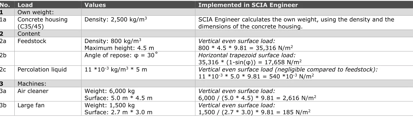
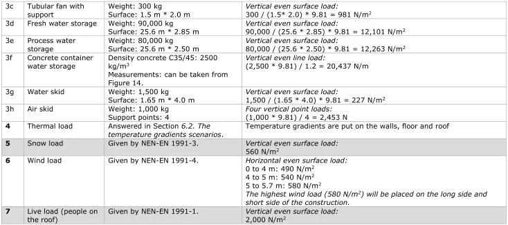
Bunkers II, III, IV, VII and VIII have the same characteristics and dimensions, so the results from one of these bunkers are equal to the results calculated in the other bunkers. The same applies to bunker V and VI. However, bunker IX and I are both different. To simplify the amount of calculations only these four bunker types are going to be used (II, III, IV, VII or VIII; and V or VI; and IX; and I). Besides the dimensions, also the loads need to be implemented in order to get a clear view on the case study situation. The forces caused by the loads are calculated. Later on these forces are used to see the total influence of the loads (thermal and the rest) on the composting bunkers. The following loads are working on the case study bunkers and need to be taken into account: 1. Own weight of the concrete construction.
2. The weight of the content: the feedstock and the percolation liquid. This works vertically on the floor.
3. The machines of the composting system. The machines are placed on the roof of the bunkers.
4. The thermal loads on the walls, floor and roof. The temperature gradients causing the thermal load are going to be determined in Section 6.2. The
temperature gradient scenarios.
5. The snow load. 6. The wind load.
7. The live load, such as people walking on the roof.
Numbers 1 and 3 are always present and are called permanent loads. The
remaining numbers are variable loads. Numbers 2 and 4 are always appearing at the same time, while 5, 6 and 7 can appear at different times and at the same time. The calculation of size of the forces and the given locations can be found in Chapter 12. Appendix B: Calculation of the forces working on the case study
bunkers.
Besides the temperature inside the bunkers, WTT doesn’t give any indication Dimensions of case study
Swisttal Value
General dimensions
Amount bunkers 9
Height bunker (internal) 5.0 m Width bunker (internal) 5.7 m Length bunker (internal) 25.0 m
Thickness
Inner wall 0.30 m
(2 * 0.30 m between V and VI)
Outer wall 0.40 m
Door 0.20 m
Floor 0.59 m
(0.30 m concrete + 0.29 m spigot floor)
thermal load. This bachelor thesis will use the temperatures from Table 7 that are taken from NEN-EN 1991-1-5 and the belonging National Appendix.
TABLE 7: THE TEMPERATURES USED IN THE CALCULATIONS FOR THE CASE STUDY USED IN THIS BACHELOR THESIS (TAKEN FROM NEN-EN 1991-1-5)
There a major differences between the temperatures used by Grotemeier Ingenieure and the temperatures used in this bachelor thesis (based on the Eurocode). Even the temperature inside the bunkers, given by WTT, is different. Grotemeier Ingenieure has taken the temperature inside the bunker during the hygienisation phase (75 ˚C), while this bachelor thesis has used the temperature inside the bunker when an error occurs (85 ˚C) as maximum temperature. The temperature during an error is higher and has thus a larger influence on the construction, but also occurs less often.
The assumed temperature for the bunker next door (empty) and the assumed outside temperature by Grotemeier Ingenieure are also lower than the
temperatures used by this bachelor thesis. However, the temperature inside the hall and in the ground are higher. There are thus a lot of differences between the temperatures used by Grotemeier Ingenieure and the temperatures given by the Eurocode. It is remarkable that some temperatures are higher and some lower. There is no pattern in the differences between temperatures used by Grotemeier Ingenieure and the temperatures given by the Eurocode.
6.1.5. CONCLUSION RESEARCH QUESTION 1
There are many differences between the three analysed reports and manuals. In the first place, the guidelines given in the manuals are broad. There’s no
explanation on why certain requirements are given by WTT. Specific guidelines need to be given and they need to be explained. These specific guidelines can contain different options the building companies can choose from. With help of the explanation given by WTT, they can choose the right options for their specific circumstances. Also the manuals need to match with each other. For example, the general and the specific manual can be integrated and adapted per project. This way there is no repetitions in the two document that can cause confusion. The loads calculated in this bachelor thesis (given in Chapter 12. Appendix B:
Calculation of the forces working on the case study bunkers) follow the Eurocode.
A few differences have been noticed between the forces calculated by Grotemeier Ingenieure and the forces calculated in this bachelor thesis. The snow load is negligibly different and the force caused by the percolation liquid isn’t taken into account by Grotemeier Ingenieure. This is however also a negligible force. As life load Grotemeier Ingenieure has a value twice as high as calculated in the
Temperatures
Bunker (filled; during an error) 85 ˚C Bunker next door (empty) 17 ˚C
Outside -25 ˚C
Hall 17 ˚C
wind force on the wall opposite of the wall on which the pushing wind force works.
The major ambiguities arise when it comes to the temperatures. WTT gives the temperatures arising in the bunker to the building companies, but other
temperatures have to be estimated by the building companies self. The differences between the calculation report of Grotemeier Ingenieure and the temperatures used in this bachelor thesis (taken from the Eurocode) can be found in Table 8. The temperatures inside the empty bunker next door and the outside temperature are estimated higher by Grotemeier Ingenieure while the temperature inside the hall and the ground temperature are lower.
There are even different temperatures used as temperature inside the filled bunkers (75 ˚C and 85 ˚C), while this information is provided by WTT. This may be related to the fact an error (85 ˚C) occurs only several times a year, so Grotemeier Ingenieure may have neglected this temperature because of that. Further research needs to point out of this simplification can be accepted. Measurements need to be taken to indicate the real temperatures that the building companies need to take into account.
TABLE 8: THE DIFFERENT TEMPERATURES USED BY GROTEMEIER INGENIEURE AND IN THIS BACHELOR THESIS.
Temperature Grotemeier
Ingenieure Bachelor thesis
Bunker (filled; during an error) 70 ˚C 85 ˚C
Bunker next door (empty) 30 ˚C 17 ˚C
Outside -12 ˚C -25 ˚C
Hall -5 ˚C 17 ˚C
6.2.
T
HE TEMPERATURE GRADIENT SCENARIOS
The concrete composting bunkers of WTT have to deal with temperature
gradients appearing in the roof, outer wall, floor and inner wall. The temperature, and with that the temperature gradient, varies and creates different scenario’s, depending on the season, the thickness of the construction part and the schedule of the feedstock (is the bunker filled with compost or not).
First, all the possible temperature gradient scenarios are listed. These scenarios are applicable in general, so these scenarios apply to all the composting bunkers of WTT over the world, apart from their location. Next, the temperature gradients are calculated using equations from Section 3.5. Creep, relaxation and
transitional thermal strain. The values for the parameters are taken from NEN-EN
1991-1-5 (including national appendix). The general scenarios are used to calculate all the temperature gradients appearing in the case study bunkers in Swisttal. Because the thickness differs per structural element (roof, outer wall, floor, inner wall), the temperature gradient differs per structural elements. So all the temperature gradients appearing the different structural elements from the case study composting bunker are calculated. Eventually one normative
temperature scenario is chosen. Using this one temperature normative scenario, the influence of the most extreme temperature gradients on the concrete is researched.
This so called normative temperature Scenario 1 Extreme occurs only several times a year. Because this scenario is rare, the most extreme common
temperature scenario (Scenario 2) is given too, so that Scenario 1 Extreme can be placed in perspective by the reader.
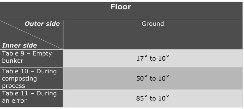
6.2.1. ALL POSSIBLE SCENARIOS
In Table 9, Table 10 and Table 11 all the possible temperature scenarios occurring in a concrete composting bunker can be found. Table 9 portrays that the bunker where the focus lies on is empty. Table 10 portrays all the scenarios where the bunker is filled with feedstock and processing it to compost. Table 11 portrays all the scenarios were an error has occurred and the temperature inside the bunker reaches a maximum.
The columns of the tables represent the outside climate situation: summer, winter or the composting bunkers are placed inside a large hall, whereby the influence of the outer climate is restricted. The rows (a to i) of the tables
represent the situation in the composting bunker next door (the numbering of the rows continues in all three tables). This bunker next door can find itself in the same three possible situations as the bunker the focus lies on in the scenario: empty, during composting process and during an error.
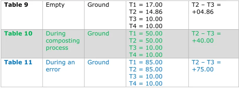
Empty bunker
A – Summer B – Winter C – Inside large hall
a
b
TABLE 10: THE POSSIBLE TEMPERATURE SCENARIOS THAT CAN APPEAR IN THE RIGHT BUNKER DURING THE COMPOSTING PROCESS.
During composting process
A – Summer B – Winter C – Inside large hall
d
e
TABLE 11: THE POSSIBLE TEMPERATURE SCENARIOS THAT CAN APPEAR IN THE RIGHT BUNKER DURING AN ERROR.
During an error
A – Summer B – Winter C – Inside large hall
g
h
The gradients appearing in the structural elements (roof, outer wall, floor, inner wall) are sorted per structural element and listed again in Table 12, Table 13 and Table 14. In the captions above to the tables is explained were the normative temperatures come from.
TABLE 12: THE TEMPERATURE DIFFERENCE SCENARIOS THAT CAN APPEAR IN THE ROOF OR OUTER WALL. THE TEMPERATURES INSIDE THE COMPOSTING BUNKER (EMPTY, DURING COMPOSTING PROCESS AND DURING AN ERROR) ARE GIVEN BY WTT. THE TEMPERATURES FOR THE SUMMER, WINTER AND INSIDE A LARGE HALL ARE GIVEN BY NEN-EN 1991-1-5 NATIONAL APPENDIX.
Roof or Outer wall
Outer side
Inner side
A – Summer B – Winter C – Inside large
[image:36.595.98.497.186.358.2] [image:36.595.96.498.419.599.2]hall
Table 9 – Empty
bunker A-a, A-b, A-c 17˚ to 51˚ B-a, B-b, B-c 17˚ to -25˚ C-a, C-b, C-c 17˚ to 17˚
Table 10 – During composting process
50˚ to 51˚
A-d, A-e, A-f B-a, B-b, B-c 50˚ to -25˚ C-a, C-b, C-c 50˚ to 17˚
Table 11 – During
an error A-g, A-h, A-i 85˚ to 51˚ B-a, B-b, B-c 85˚ to -25˚ C-a, C-b, C-c 85˚ to 17˚
TABLE 13: THE TEMPERATURE DIFFERENCE SCENARIOS THAT CAN APPEAR IN THE FLOOR. THE TEMPERATURES INSIDE THE COMPOSTING BUNKER (EMPTY, DURING COMPOSTING PROCESS AND DURING AN ERROR) ARE GIVEN BY WTT. THE TEMPERATURE FOR THE GROUND IS GIVEN BY NEN-EN 1991-1-5 NATIONAL APPNEN-ENDIX.
Floor
Outer side
Inner side
Ground
Table 9 – Empty
bunker 17˚ to 10˚
Table 10 – During composting
process 50˚ to 10˚
Table 11 – During
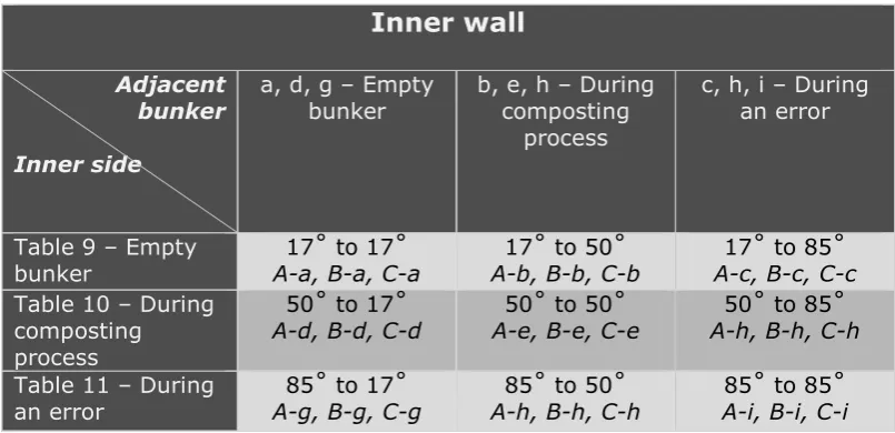
TABLE 14: THE TEMPERATURE DIFFERENCE SCENARIOS THAT CAN APPEAR IN THE INNER WALL. THE TEMPERATURES INSIDE THE COMPOSTING BUNKER (EMPTY, DURING COMPOSTING PROCESS AND DURING AN ERROR) AND INSIDE THE ADJACENT BUNKER (EMPTY, DURING COMPOSTING PROCESS AND DURING AN ERROR) ARE GIVEN BY WTT.
Inner wall
Adjacent bunker
Inner side
a, d, g – Empty
bunker b, e, h – During composting process
[image:37.595.93.496.120.315.2]c, h, i – During an error
Table 9 – Empty
bunker A-a, B-a, C-a 17˚ to 17˚ A-b, B-b, C-b 17˚ to 50˚ A-c, B-c, C-c 17˚ to 85˚
Table 10 – During composting process
50˚ to 17˚
A-d, B-d, C-d A-e, B-e, C-e 50˚ to 50˚ A-h, B-h, C-h 50˚ to 85˚
Table 11 – During
an error A-g, B-g, C-g 85˚ to 17˚ A-h, B-h, C-h 85˚ to 50˚ A-i, B-i, C-i 85˚ to 85˚
6.2.2. EQUATIONS AND PARAMETERS
The temperature gradients appearing in the structural components are calculated using Equation 21 and Equation 2 (see also Figure 6 mentioned in Section 3.5. Creep, relaxation and transitional thermal strain)
Rtotal [𝑚2K/W] = ( 1
U ) = Ri + Rc + Ro = 1 αi+ h λ+ 1 αo (21)
ΔTseperate layer [˚] = Ri 𝑜𝑟 Rc 𝑜𝑟 Ro
Rtotal ∗ (T1 − T4)
(22)
The parameters from the equations are explained below. The values for the parameters in different scenarios can be found in Table 15 and Table 16. o Ri [m2K/w]:
This value depends on the material on the inside of the structural element; so inside the bunker. The material on the inside can be either air, when the bunker is empty, or compost, when the composting process is in progress or when an error occurs. Because compost resembles a combination of water and ground, the R belonging to ground & water is taken as the Ri of compost
from NEN-EN 1068. The value of air depends on whether the air find itself inside or outside a building, where airflow lowers the Ri-value.
o Ro [m2K/w]:
This value depends on the material outside the structural element. The outside can consist of air, compost (when the outside finds itself inside a bunker next door in case of an inner wall) or ground (when the structural element is a floor). Also here depends the value of air on whether the air find itself inside or outside a building.
o λ [W/m˚C]:
o h [m]:
The thickness of the structural element. The possible structural elements are: inner wall, outer wall, floor and roof (these can also be found in Table 12, Table 13 and Table 14).
TABLE 15: THE VALUES OF THE MATERIAL RELATED PARAMETERS. THESE ARE USED TO CALCULATE THE TEMPERATURE GRADIENTS APPEARING IN THE CASE STUDY BUNKER IN SWISTTAL. THE RI AND
RO AND TAKEN FROM NEN-EN 1068.
Parameter Material Value Scenario
Ri Air (inside): 0.13 m2K/w Table 9
Compost (water & ground): 0.00 m2K/w Table 10 and Table 11
Ro Air (outside): 0.04 m2K/w Columns A & B Air (inside): 0.13 m2K/w Row a, d and g
Ground: 0.00 m2K/w All scenarios
Compost (water & ground): 0.00 m2K/w Row b, c, e, f, h and i
λ Concrete: 2.0 W/m˚C
TABLE 16: THE THICKNESSES OF THE DIFFERENT STRUCTURAL ELEMENTS. THE APPEARING TEMPERATURE GRADIENTS DEPENDS ON THE THICKNESS.
Parameter Structural element Value Table
h Outer wall: 0.40 m Table 12
Roof: 0.28 m Table 12
Floor: 0.59 m
(0.30 + 0.29)
Table 13
Inner wall: 0.30 m Table 14
(Door:) (0.20 m) (-)
6.2.3. CALCULATED TEMPERATURE GRADIENTS
The general scenarios from Table 9, Table 10 and Table 11 are used to study the temperature gradients that can appear in the case study situation. First all the temperature gradients appearing in the structural elements of all the scenarios are calculated. The results of these calculations can be found in Chapter 13. Appendix C: All calculated temperature gradients. The temperature gradients that are part of Scenario 1 Extreme scenario (Scenario B-g in Table 11) are coloured blue in the appendix and when they are part of the common scenario, they are coloured green. Assumed is that the temperature in the concrete stays the same, because the composting time (2 – 3 weeks) is far longer than the interim time (1 day).
6.2.4. TWO NORMATIVE CASE STUDY SCENARIOS
From all the calculated scenarios the most extreme is going to be used as normative thermal load in the calculations. This from now on called Scenario 1
Extreme contains the most extreme temperature gradients that can appear in
VI is twice as thick as the other inner walls. The temperature gradient over this wall is thus different from the other inner walls. The calculated temperature gradients can be found in Table 17.
TABLE 17: THE TEMPERATURE GRADIENTS APPEARING IN EXTREME NORMATIVE SCENARIO. T1 IS THE TEMPERTURE INSIDE THE BUNKER AND T4 IS THE TEMPERATURE OUTSIDE THE BUNKER.
Scenario B-g: Scenario 1 Extreme winter
Structural element Temperature gradient
Roof T1 = 85.00
T2 = 85.00 T3 = -00.56 T4 = -25.00 Outer wall
(The outer wall of bunker IX is
partially outside and partially inside a large hall)
T1 = 85.00 T2 = 85.00 T3 = -06.67 T4 = -25.00
T1 = 85.00 T2 = 85.00 T3 = 43.79 T4 = 17.00
Floor T1 = 85.00
T2 = 85.00 T3 = 10.00 T4 = 10.00
Inner wall T1 = 85.00
T2 = 85.00 T3 = 48.57 T4 = 17.00
(The inner wall between bunker V and VI is twice as thick as a normal inner wall)
T1 = 85.00 T2 = 85.00 T3 = 37.56 T4 = 17.00
TABLE 18: THE TEMPERATURE GRADIENTS APPEARING IN COMMON NORMATIVE SCENARIO. T1 IS THE TEMPERTURE INSIDE THE BUNKER AND T4 IS THE TEMPERATURE OUTSIDE THE BUNKER.
Scenario B-d: Common winter
Structural element Temperature gradient
Roof T1 = 50.00
T2 = 50.00 T3 = -08.33 T4 = -25.00 Outer wall
(The outer wall of Bunker IX is
partially outside and partially inside a large hall)
T1 = 50.00 T2 = 50.00 T3 = -12.50 T4 = -25.00
T1 = 50.00 T2 = 50.00 T3 = 30.00 T4 = 17.00
Floor T1 = 50.00
T2 = 50.00 T3 = 10.00 T4 = 10.00
Inner wall T1 = 50.00
T2 = 50.00 T3 = 32.32 T4 = 17.00
(The inner wall between bunker V and VI is twice as thick as a normal inner wall)
T1 = 50.00 T2 = 50.00 T3 = 26.98 T4 = 17.00
The temperature gradients of Scenario 1 Extreme appearing in the concrete layers (the difference between T2 and T3) are going to be implemented in Scia Engineer. This scenario is thus going to be used to calculate the stress and forces that appear in the case study bunkers, which create the cracks in the concrete.
6.2.5. CONCLUSION RESEARCH QUESTION 2
There are twenty-seven temperature scenarios that can occur in a concrete composting bunker of WTT. This bachelor thesis will use the most extreme scenario in the calculations to look at the influence of the temperature on the concrete (Scenario 1 Extreme). The Eurocode is followed in determining the temperatures in all these scenarios.