http://dx.doi.org/10.4236/opj.2013.32027 Published Online June 2013 (http://www.scirp.org/journal/opj)
Performance Analysis of WDM RoF-EPON Link with
and without DCF and FBG
Baljeet Kaur1, Ajay K. Sharma2, Vinod Kapoor3
1Department of Electronics and Communication Engineering, Guru Nanak Dev Engineering College, Ludhiana, India 2Department of Computer Science and Engineering, National Institute of Technology, Jalandhar, India 3Department of Electronics and Communication Engineering, National Institute of Technology, Hamirpur, India
Email: [email protected], [email protected], [email protected]
Received March 8, 2013; revised April 10, 2013; accepted April 17, 2013
Copyright © 2013 Baljeet Kaur et al. This is an open access article distributed under the Creative Commons Attribution License, which permits unrestricted use, distribution, and reproduction in any medium, provided the original work is properly cited.
ABSTRACT
Performance of WDM ethernet passive optical network (EPON) with radio over fiber (RoF) optical link has been ana- lyzed with the use of dispersion compensating fiber (DCF) and fiber bragg grating (FBG) to compensate the dispersion and four wave mixing. With the use of DCF and FBG, performance of the system is improved by 77.67%. Results are compared with and without DCF + FBG for different optical power and fiber length. The BER, Q factor and eye dia- grams have been obtained for evaluating the performance of the system.
Keywords: Optical Network Unit; Optical Line Termination; BER; EPON; RoF; DCF; FBG
1. Introduction
As in a cellular system both increased traffic and propa- gation properties of millimeter-waves require small cells, further as millimeter-wave circuits are rather expensive, the cost of base stations will be of determining role. To satisfy this increasing demand, the high capacity of opti- cal networks should be integrated with the flexibility of radio networks. RoF technique for the WDM-EPON has been researched to make optical network unit (ONU) support both wired and wireless services [1-3]. When multiple wavelengths carrying WDM signals propagate in single fiber, dispersion and fiber nonlinearities can lead to crosstalk between carriers. Dispersion is the spread- ing of light pulses when they travel down through optical fiber, which results in distortion of the signal. It leads to broadening of optical pulses transmitted along a fiber and the detection of individual pulses at the receiver is not easily possible. This misinterpretation of pulses results in Inter-symbol Interference (ISI) which leads to poor BER performance. For dispersion compensation the use of dis- persion compensated fiber (DCF) is an important method and it also upgrades the already installed links of single mode fiber [4,5]. The DCFs are specially designed fibers with negative dispersion. The high value of negative dis- persion is used to compensate for positive dispersion over large lengths of ordinary fiber. In dispersion man- agement technique, consider the situation in which each
optical pulse propagates through two fiber segments, the second of which is DCF [6,7].
parameters for the designing are taken according to IEEE 802.3 ah standard [15].
For analysis, in downstream direction, we have con- nected four channels 1552.5, 1551.72, 1550.91, and 1550.11 nm wavelengths with 0 dBm power and 15 GHz radio frequency. The designing inside first subsystem is shown in Figure 2. Eight ONUs are connected at the
receiver side, which again divide the signal into four re- ceivers, so total 32 users can receive the signal simulta- neously.
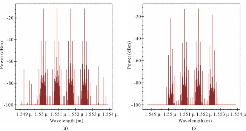
These four subsystems are combined through WDM MUX and transmitted through bidirectional SMF then distributed via splitter to eight ONUs. To compensate dispersion and FWM, DCF and FBGs are used respec- tively. Design parameters are shown in Table 1. After
passing through DCF output power is reduced to 1 dBm, then two FBGs are used. First FBG remove the signals, which are greater than fourth channel wavelength 1552.5 nm and second FBG remove the signals less than first channel wavelength 1550.11 nm. The Output spectrum before FBG (after bidirectional fiber) and then after FBG
Table 1. Design parameters.
Parameter Value (IEEE 802.3 ah Standard)
Maximum bit rate 1.25 Gbps
Dispersion
(bidirectional optical fiber) 16.75 ps/nm/km
Dispersion slope
(bidirectional optical fiber) 0.075 ps/nm2/km
Attenuation constant
(bidirectional optical fiber) 0.2 dB/km
Effective area
(bidirectional optical fiber) 80 µm2
Length (DCF) 4 km
Dispersion (DCF) −50 ps/nm/km
Dispersion Slope (DCF) 0.001 ps/nm2/km
First FBG wavelength 1552.5 nm
[image:2.595.90.536.287.722.2]Second FBG wavelength 1550.11 nm
[image:2.595.61.538.288.725.2]165
Figure 2. Designing inside first subsystem at the transmitter.
[image:3.595.92.504.295.515.2]
(a) (b)
Figure 3. Output spectrum (a) Before FBG; (b) After FBG.
3. Results and Discussion
The simulation setup of Figure 2 is employed to
com-pensate dispersion and FWM for WDM RoF-EPON Link. DCF and FBG are used after bidirectional optical fiber for the compensation. DCF provides an optical medium with a relatively large negative chromatic dispersion fac- tor (D(λ)) at the operating wavelength. DCF are more mature, stable and not easily affected by temperature. DCF has become a most useful method of dispersion compensation and has been extensively studied. Simi- larly FWM can have important deleterious effects in op- tical fiber communications, particularly in the context of wavelength division multiplexing, where it can cause cross- talk between different wavelength channels, and/or an imbalance of channel powers.
To select the dispersion value for DCF, we have ana- lyzed the output for different dispersions.
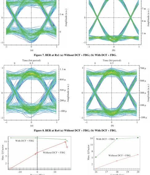
From Figure 6, we are getting maximum Q factor at −50 ps/nm/km dispersion value. Further to compensate FWM, two FBGs at 1550.11 and 1552.5 nm wavelengths are used to remove signals before first and after fourth channel frequency. Eye diagrams are compared at ONUs. BER patterns at ONU1 for Rx1 and Rx4 with and with- out DCF+ FBG are shown in Figures 7 and 8 respec-
tively.
By comparing the BER patterns of Figures 7 and 8 at
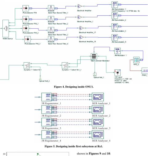
Figure 4. Designing inside ONU1.
Figure 5. Designing inside first subsystem at Rx1.
Figure 6. Output for different dispersion values.
shown in Figures 9 and 10.
We analyzed that the performance of the system can be enhanced by compensating dispersion and FWM with the use of DCF and FBG.
4. Conclusion
167
[image:5.595.57.539.85.303.2]
(a) (b)
Figure 7. BER at Rx1 (a) Without DCF + FBG; (b) With DCF + FBG.
[image:5.595.54.540.137.705.2]
(a) (b)
[image:5.595.81.540.324.546.2]Figure 8. BER at Rx4 (a) Without DCF + FBG; (b) With DCF + FBG.
Figure 9. Q factor with and without DCF + FBG for differ-ent input power at Rx1.
[image:5.595.336.509.582.706.2]ference, Victoria, 3-5 October 2007, pp. 24-28.
[4] W. Chen, S. Y. Li, P. X. Lu, D. X. Wang and W. Y. Luo, “Dispersion Compensation Optical Fiber Modules for 40 Gbps WDM Communication Systems,” Frontiers of Op- toelectronics in China, Vol. 3, No. 4, 2010, pp. 333-338. doi:10.1007/s12200-010-0117-6
[5] G. P. Agrawal, “Nonlinear Fiber Optics,” 2nd Edition, Academic Press, San Diego, 1995.
[6] M. I. Hayee and A. E. Willner, “Pre- and Post-Compensa- tion of Dispersion and Linearities in 10-Gb/s WDM,”
IEEE Photonics Technology Letters, Vol. 9, No. 9, 1997, pp. 1271-1273.
[7] C. Caspar, H.-M. Foisel, A. Gladisch, N. Hanik, F. K. Uppers, R. Ludwig, A. Mattheus, W. Pieper, B. Strebel and H. G. Weber, “RZ versus NRZ Modulation Format for Dispersion Compensated SMF-Based 10-Gb/s Trans- mission with More than 100-km Amplifier Spacing,” IEEE Photonics Technology Letters, Vol. 11, No. 4, 1999, pp.
Optical Communications and Beyond,” International Jour- nal of Advances in Optical Communication and Networks, Vol. 1, No. 1, 2010, pp. 17-22.
[12] Z. Pan, Y. Xie, S. Lee and A. E. Willner, “Tunable Com- pensation for Polarization-Mode Dispersion Using a Bi- refringent Nonlinearly-Chirped Bragg Grating in a Dual- Pass Configuration,” US Patent 6400869, 2002.
[13] X. Kun, F. Jia, X. Chen, M. Jin, M. Chen, X. Li and S. Xie, “A Novel Adjustable PMD Compensation Using Sam- pled Bragg Gratings with Uniform Grating Period,” Op- tics Communications, Vol. 202, No. 4-6, 2002, pp. 297- 302. doi:10.1016/S0030-4018(02)01111-2
[14] V. Kumar, B. Kaur and A. K. Sharma, “A Comparative Analysis of WDM RoF-EPON Link with and without DCF,” International Conference (ICMEME 2012), Bang- kok, 17-18 March 2012, pp. 31-34.