An Encryption Algorithm for Secure Data Transmission
Rohan Rayarikar
B.E Student
Dept. of Computer Engineering Thakur College of Engineering
& Technology, Mumbai, India.
Sanket Upadhyay
B.E Student
Dept. of Computer Engineering Thakur College of Engineering &
Technology, Mumbai, India.
Deeshen Shah
B.E Student
Dept. of Computer Engineering K. J. Somaiya College of engineering, Mumbai, India.
ABSTRACT
Encryption is of prime importance when confidential data is transmitted over the network. Varied encryption algorithms like AES, DES, RC4 and others are available for the same. The most widely accepted algorithm is AES algorithm. We have proposed a new algorithm based on the concept used by Rijmen and Daemen (Rijndael algorithm), the founders of AES algorithm. The proposed algorithm encrypts and decrypts two 128 bits data simultaneously i.e. 256 bits data, thus providing strong encryption accompanied with complex processing. The proposed Feistal algorithm uses various invertible, self-invertible, and non-invertible components of modern encryption ciphers and key generation same as that of AES. This algorithm provides a secure, fast, and strong encryption of the data. There is a huge amount of confusion and diffusion of the data during encryption which makes it very difficult for an attacker to interpret the encryption pattern and the plain text form of the encrypted data. The proposed algorithm is also resistant to Brute-Force and pattern attacks.
General Terms
Security Algorithm, Symmetric Key Encryption.
Keywords
Encryption Algorithm, S-Box Substitution, Complement, Feistal, ELT, ERT, EBT, LPT and RPT.
1.
INTRODUCTION
Security of data is of prime importance in today’s world. With every passing day, cryptanalysis is successful on some or the other algorithm. Thus, it is very important that the algorithm used for encryption of data is resistant to cryptanalysis. Along with being resistant, it is equally important that the algorithm uses optimum system resources. One of the most successful algorithms till date is the AES algorithm proposed by Rijmen and Daemen (Rijndael algorithm) in June 1998. This algorithm is being used in many different applications. The main feature of AES algorithm which makes it more secure over the others is its unique round transformations and the Rijndael key scheduling algorithm. In this proposed algorithm we have used the round transformation concept of AES algorithm, making changes in the components of the rounds along with their ordering. The proposed Feistal algorithm would be more secure and would be resistant to cryptanalysis.
2.
PROPOSED ENCRYPTION
ALGORITHM
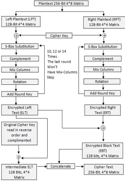
The following is the proposed algorithm for data encryption- The plain text or the user text is arranged in a 4*8 matrix i.e. 2 * 128 bits. The reason behind this is that, more number of bits can be processed in same amount of time as required to process data arranged in 4*4 matrix i.e. 128 bits, in case of AES.
Fig 1: 4*8 State Matrix
[image:1.595.358.500.195.307.2]The key is generated using Rijndael’s key scheduling algorithm. The generated key is the most important element in this process as it is the key which decides the permutations and order of components to be used in the algorithm. This helps in confusion and diffusion in the proposed algorithm. Based on the length of the key, the number of rounds in the algorithm is decided. There can be 10, 12 or 14 rounds for keys of length 128 bits, 192 bits or 256 bits. A new round key is generated for each round based on the key scheduling algorithm. The following are the steps carried out. [2]
[image:1.595.323.535.422.731.2]2.1
Matrix Division
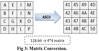
Matrix Division is the first step in the algorithm. The 4*8 matrix is divided into two 4*4 matrices. The division is carried out based on the predefined order. The two matrices thus obtained are known as Left Plain Text (LPT) and Right Plain Text (RPT). The LPT and RPT contain the user data in plain text form. The data in these matrices is then converted into hexadecimal form. An example of 128 bit plain text matrix converted into hexadecimal form is shown in the figure below.
Fig 3: Matrix Conversion.
The user inputted key, known as cipher key is XOR-ed with each plain text matrix respectively. The output is given as input to the next step. The steps which follow Matrix Divisions are repeated over n times based on the length of the cipher key. This is analogous to Round Transformations in AES algorithm. [3]
2.2
S-Box Substitution
This step is same as SubBytes step of AES algorithm. In the S-Box Substitution step, each byte in the matrix is reorganized using an 8-bit substitution box. This substitution box is called the Rijndael S-box. This operation provides the non-linearity in the cipher. The S-box used is derived from the multiplicative inverse over GF (28), known to have good non-linearity properties. To avoid attacks based on simple algebraic properties, the S-box is constructed by combining the inverse function with an invertible affine transformation. The S-box is also chosen to avoid any fixed points (and so is a derangement), and also any opposite fixed points. [7] This step causes confusion of data in the matrix. S-Box Substitution is carried out separately for LPT and RPT. This is the first step of iterative round transformation. The output of this round is given to the next round. [2]
2.3
Complement
This is the second step of the transformation, which completely changes the data based on the round key. The round keys generated in this algorithm are of size 128 bits. The 128 bit state matrix contains 16 words each of size 8 bits. Therefore, the maximum value of any word in binary form is 1111 1111. If the round key of size 128 bits is divided by 16 we get the output as 8. This means that 8 bits of round key can be associated with one word. Therefore, the round key is divided into 16 groups; each group consisting of 8 bits data. Each group is associated to one word, which means 16 groups can be associated to corresponding 16 words.
In this step we take the complement of the bits in the words based on the position of the 0s in the corresponding group of the round key.
For example if the first group of round key is 00111100; the position of 0s in the above group is 0, 1, 6 and 7. Therefore the positions 0, 1, 6 and 7 of the first word, i.e. word corresponding to position (1, 1) of the state matrix, are complemented and rest of the bits are kept the same. The
same operation is carried out for the entire matrix; thereby completely changing the data in the state matrix matrix.
2.4
MixColumns
In the MixColumns step, the four bytes of each column of the state matrix are combined using an invertible linear transformation. A randomly generated polynomial is arranged in a 4*4 matrix. The same polynomial is used during decryption. Each column of the state matrix is XOR-ed with the corresponding column of the polynomial matrix. The result is updated in the same column. This step is carried out individually for both LPT and RPT. This step is same as the MixColumns step in AES algorithm.
2.5
Rotation
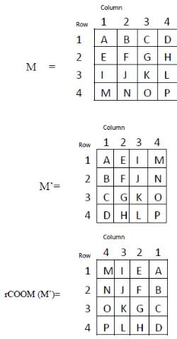
[image:2.595.56.254.189.291.2]This is a new kind of rotation that was proposed in [4]. In this kind of rotation, entire 2D Array block is rotated by certain angle depending upon certain value of the key bits. Its use will increase the confusion aspect in the information bytes when transformed to the ciphertext. The two operations on matrices are denoted by, rCOOM (M) that denotes reverseColumnsOrderOfMatrix M i.e. function that arranges the columns of the matrix M in reverse order and rROOM(M) that denotes reverseRowsOrderOfMatrix M i.e. function that arranges the rows of the matrix in reverse order. Also the standard notation M’ is used to denote the transpose of a matrix M. The entire block is rotated in clockwise direction by an amount of 0°, 90°, 180°, 270° during encryption depending upon the 2 bits of the key value 00,01,10,11 respectively. The table below represents the operations carried out. [4]
Table 1: Rotation Table
Key Bit Value
Rotation in Degrees (Clockwise
Direction)
Operations carried on the matrix
00 0 M
01 90 rCOOM(M’)
10 180 rROOM(rCOOM(M)) 11 270 rROOM(M’)
For key bit value 00 the matrix remains the same. For key bit value 01 the matrix rotates by 90
degrees. The operation corresponding to this rotation is rCOOM (M’) where we arrange the columns of the matrix M’ in reverse order as shown in the figure below.
For key bit value 01 the matrix rotates by 180 degrees. The operation corresponding to this rotation is rROOM (rCOOM (M)) where we first arrange the columns of the matrix M in reverse order followed by arranging the rows of the newly generated matrix in reverse order.
For key bit value 11 the matrix rotates by 270 degrees. The operation corresponding to this rotation is rROOM (M’) where we arrange the rows of the matrix M’ in reverse order.
Fig 4: Rotation of 2D Array
2.6
Add Round Key
This is the last step of the round transformation. In this step the round key generated using the key scheduling algorithm is XOR-ed with the matrix given input to this step. The key is arranged in a 4*4 matrix. The XOR operation takes place column-wise i.e. first column of round key matrix is XOR-ed with the first column of the inputted matrix. For every round a new round key is generated. For a particular round, same round key is used to encrypt LPT and RPT. [2]
2.7
Cipher Text Generation
The operations described in 2.2, 2.3, 2.4, 2.5 and 2.6 are repeated (n-1) number of times based on the length of the cipher key; the value of n never exceeds 14. However, for the nth round we do not include MixColumns step. This is based on the Rijndael’s concept.
We obtain Encrypted Left Text (ELT) and Encrypted Right Text (ERT) after the round transformation. ELT and ERT are XOR-ed to form Encrypted Block Text (EBT) which is of 128 bits.
Furthermore, the original cipher key (128 bits) is inverted i.e. read backwards and is then complemented. The then obtained 128 bit key is XOR-ed with the ELT to form 128 bits Intermediate ELT.
Finally, the Intermediate ELT is concatenated with EBT to form 256 bit Cipher Text. The concatenation process takes place based on the key used in algorithm. The Cipher Text obtained is transmitted over the network.
2.8
Round Transformations
The order of components in the round transformation differs from one round to other except Add Round Key component that is always executed at the end of each round. The key matrix defines this order as shown in the figure below. The key generated using the key scheduling is arranged in a 4*4 matrix. The first row of the key matrix contains four words. Each word has a two bit hexadecimal value. First two words define the order of execution of the left round transformation and the last two words define the order of the right round
transformation. Consider first two words of the matrix. It contains total of 4 hexadecimal values. These values are read from left to right. Each value corresponds to a specific component in the following order; S- Box, Complement, Mix-Columns, and Rotation. The component corresponding to least hexadecimal value is executed first. If the values are same, then the components are executed in the order given above. The same process is repeated for the right round transformations. This process helps to make the algorithm more secure by confusing and diffusing data to maximum extent. The decryption takes place in reverse order.
[image:3.595.326.521.213.379.2]
Fig 5: Round Key Usage
3.
DECRYPTION OF THE PROPOSED
ALGORITHM
The encryption algorithm is referred to as the cipher and the decryption algorithm as the inverse cipher. In addition, the cipher and the inverse cipher operations must be executed in such a way that they cancel each other. The rounds keys must also be used in reverse order. The Cipher Text which is formed of 256-bit 4*8 Matrix is the input for the decryption process.
3.1
Encrypted Text Generation
The Cipher text is split into Left Cipher Text (LCT) and Right Cipher Text (RCT) based on the permutation with which it was concatenated in the encryption process. Now in order to obtain the Encrypted Left Text (ELT) and Encrypted Right Text (ERT), we XOR the LCT with modified cipher key used in the last step of encryption process i.e. by reading the original cipher key in opposite direction (right to left) & then complementing it. The ELT is XOR-ed with the RCT to obtain ERT. Thus, we obtain both ELT and ERT. The following operations are carried out on the ELT and ERT separately repeated over n number of times so as to get the LPT and RPT.
3.2
Inverse S-Box
3.3
Complement
The key used for performing complement of plaintext, is same for performing complement of cipher text. As explained in the Encryption process, we take the complement of the bits in the words based on the position of the 0s in the corresponding group of the round key.
3.4
InvMixColumns
The InvMixColumns operation is same as the MixColumns operation. The two matrices used for encryption and decryption operation are inverses of each other. The operations are carried out on the data matrix in exactly the reverse order as that of encryption process. As mentioned earlier, a randomly generated polynomial is arranged in a 4*4 matrix which is used for transformation. This step is carried out individually for both Encrypted Left Text (ELT) and Encrypted Right Text (ERT). [2]
3.5
Inverse Rotation
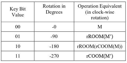
[image:4.595.55.279.379.490.2]The inverse rotation takes place in opposite direction as that of the rotation step in the encryption process. The matrix is rotated in anti-clockwise direction. The operations performed on the matrix during decryption are same as that performed during encryption, but the order of operation changes. The table below explains the operations corresponding to the four angles for decryption process. [4]
Table 2: Inverse Rotation Table
Key Bit Value
Rotation in Degrees
Operation Equivalent (in clock-wise
rotation)
00 -0 M
01 -90 rROOM(M’)
10 -180 rROOM(rCOOM(M))
11 -270 rCOOM(M’)
3.6
Add Round Key
This is the same step which is performed in the encryption process. The round key generated is XOR-ed with the matrix given input to this step. The key is arranged in a 4*4 matrix. The XOR operation takes place column-wise i.e. first column of round key matrix is XOR-ed with the first column of the inputted matrix. For every round a new round key is generated. For a particular round, same round key is used to decrypt ELT and ERT. The round keys used for decryption are in opposite direction as that of encryption. For example, nth round key is used for nth round in case of encryption where as in case of decryption it is used for first round.
3.7
Generation of Plain Text
After performing the iterative round transformation, we get the Left Plain Text (LPT) and Right Plain Text (RPT). Both these text are matrices of size 128 bits each i.e. 4*4 matrix. These matrices are merged to obtain the plaintext i.e. 4*8 matrix- 256 bits. This is the original plain text which was encrypted by the sender.
4.
IMPLEMENTATION
The proposed algorithm can be implemented in any language. This algorithm can also be used in Image Processing. We have implemented it in java, java being an open source and platform independent language. The pseudo codes for the components of the cipher are given below.
4.1
Add Round key:
public byte[ ][ ] addRoundKey(byte[ ][ ] state,byte[ ][ ] roundkey)
{
for (int i=0;i<4;i++) {
for (int j=0;j<4;j++) {
state [i][j]=doExclusiveOR(state[i][j], roundkey[i][j]);
} }
return state; }
4.2
Substitute Bytes:
public byte[ ][ ] subBytes(byte[][] state) {
for (int i=0;i<4;i++) {
for (int j=0;j<4;j++) {
int row = getFirstFourBits(state[i][j]); int column =
getSecondFourBit(state[i][j]); state[i][j] = sBoxSubstitution(row,column);
} }
return state; }
4.3
MixColumns:
public byte[ ][ ] mixColumns(byte[ ][ ] state) {
for (int c=0;c<4;c++) {
state [c]=matrixMultiplication(state[c], polynomial); }
return state; }
4.4
Complement:
public byte[ ][ ] complement(byte[ ][ ] state) {
for (int i=0;i<4;i++) {
for (int j=0;j<4;j++) {
state [i][j] = doCompelement(state[i][j]); }
}
4.5
Rotation:
public byte[ ][ ] rotation(byte[ ][ ] state, int degree) {
for (int i=0;i<4;i++) {
for (int j=0;j<4;j++) {
state [i][j] = byteRotatedByDegree(state[i][j],degree);
} }
return state; }
5.
STRENGTH OF THE PROPOSED
ALGORITHM
The cipher key used in the proposed algorithm is of 128 bits. Therefore, to break the cipher key an attacker has to check 2128 possibilities which are practically almost impossible. Therefore, the Brute-force Attack fails on this algorithm. The flow of the algorithm makes sure that there is no fixed pattern in any of the steps of the algorithm. The components of the proposed algorithm have brought about strong diffusion and confusion. Therefore, statistical and pattern analysis of the ciphertext fails.
The Rotation component used in this algorithm has made the algorithm turn to a Feistal structure. [4]
The most important security advantage is that no differential
or linear attacks can break this algorithm.
6.
ACKNOWLEDGEMENT
The Rotation and Inverse Rotation mechanisms are considered as a tentative solution that has been introduced by Dr. (Mrs) Pushpa R. Suri and and Sukhvinder Singh Deora, in “Design of a modified Rijndael algorithm using 2D Rotations”, IJCSNS International Journal of Computer Science and Network Security, VOL.11 No.9, September 2011. We would later propose a mechanism which would operate as an alternative for the Rotation and Inverse Rotation steps in the proposed algorithm.
7.
CONCLUSION
The proposed algorithm is very secure for data encryption. It is resistant to cryptanalysis. The algorithm makes use of Rijndael concept; therefore, the strengths of Rijndael are preserved. The proposed algorithm being Feistal increases confusion and diffusion of the data. It is very difficult for an intruder or an attacker to decrypt the data without the key of the algorithm.
8.
REFERENCES
[1] J. Daemen and V. Rijmen, AES Proposal: Rijndael, NIST’s AES home page, http ://www:nist:gov/aes.
[2] “Announcing the Advanced Encryption Standard (AES)”, Federal Information Processing Standards Publication 197, November 2001
[3] Priyanka Pimpale, Rohan Rayarikar and Sanket Upadhyay, “Modifications to AES Algorithm for Complex Encryption”, IJCSNS International Journal of Computer Science and Network Security, VOL.11 No.10, October 2011.
[4] Dr (Mrs) Pushpa R. Suri and Sukhvinder Singh Deora, “Design of a modified Rijndael algorithm using 2D Rotations”, IJCSNS International Journal of Computer Science and Network Security, VOL.11 No.9, September 2011.
[5] Xinmiao Zhang and Keshab K. Parhi, “Implementation Approaches for the Advanced Encryption Standard Algorithm”, 1531-636X/12, IEEE 2002.
[6] Chun Yan,Yanxia Guo, “A Research and Improvement Based on Rijndael Algorithm”, 2009 First International Conference on Information Science and Engineering, Nanjing, Jiangsu China, December 26-December 28, ISBN: 978-0-7695-3887-7