4Nippon Steel Corporation, Futtsu 293-8511, Japan
Experiments on bend forming of a bumper model with a 9.8-MN oil-hydraulic press and FEM analysis with the static code MARC were carried out in order to investigate springback behavior. The materials used were three types of high-strength steel sheets (HSS) of 440–780-MPa class. Experimental springback shapes were investigated using a 3-D measuring machine. The springback of a formed bumper increased with an increase in yield stress (YS) of the material, coinciding with the results of 2-D FEM simulation.
(Received July 19, 2002; Accepted January 21, 2003)
Keywords: final element method (FEM) analysis, bend forming, bumper model, springback, 2-D simulation
1. Introduction
At the Kyoto International Conference for the improve-ment of the global environimprove-ment, target values were estab-lished for reducing gas emissions in order to prevent global warming. Subsequently, investigations have been conducted on reducing carbon dioxide emissions from such sources as automobile fuel, batteries and engines. For this reason, weight reduction of an automobile body has become increasingly urgent.
The use of high-strength steel sheets (HSS) and aluminum alloy sheets has increased and in Japan, usage of HSS on automobile bodies is actively promoted. Studies on HSS, taking into account factors such as surface deflection and shape accuracy,1) as well as manufacturing and forming technologies2) have been conducted. However, HSS are difficult to form and the amount of springback is large, creating difficulties in controlling the springback in auto-mobile parts such as frames and bumpers in which forming is mainly composed of bending. Regarding springback, an explanation of bend forming,3) a lecture from a mechanical point of view,4) analysis by FEM5) have previously been reviewed. More recently, key reports have been presented on an elementary method of analysis,6)an incremental theory of elastic-plastic strain,7) a structural model incorporating the Baushinger effect,8)and analyses by static explicit FEM.9,10) However, these analyses are mostly on comparatively simple shapes, such as those obtained by hat forming.8,9)There have been few reports of experiments on near-actual complex-shaped parts by FEM analysis.
This paper describes a forming experiment of a bumper model using a large 9.8-MN press, the measurement of springback shapes by a 3-D shape-measuring machine, and the comparison of these results with numerical results obtained by a simulation of static implicit FEM. In addition, forming simulation by FEM was conducted by changing the material properties and forming conditions so that the effects on springback could be investigated.
2. Experimental Method and Shape-Measuring Method
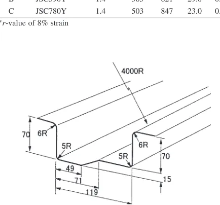
Three types of HSS of 440–780 class with a thickness of 1.4 mm were used as test specimens. Their mechanical properties are shown in Table1. Using a large 9.8-MN press, experiments on the bend forming of a bumper model with a 4000R radius of curvature in the longitudinal direction, a cross section of which is shown in Fig.1, were performed. A 300300mm2 blank was used with a rolling direction
[image:1.595.303.549.519.586.2]coinciding with the longitudinal direction of the punch. Figure2 shows an outline of the forming process. First, a stepped shape of a punch bottom was formed at a cushion pressure of 150 kN (which corresponds to 4.12 MPa in back pressure), then the blank was bent to 70 mm in depth without blank holding. Finally, the forming load was removed in the
Table 1 Materials and their mechanical properties.
Symbol Steel grade Thickness YS TS El r t/mm /MPa /MPa /% (15%)
A JSC440W 1.4 317 464 35.3 1.38 B JSC590Y 1.4 365 621 29.0 0.89 C JSC780Y 1.4 503 847 23.0 0.79 r-value of 8% strain
Fig. 1 Schematic illustration of bumper model.
*1This Paper was Originally Published in Japanese in the Journal of JSTP,
43 (2002) 219.
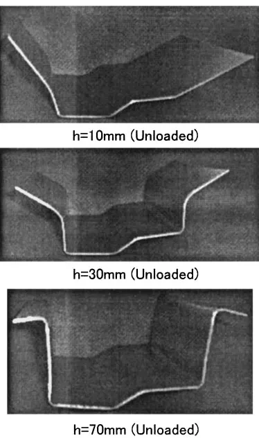
[image:1.595.312.529.566.768.2]order of cushion pressure, punch and die. Clearance for this press forming was defined as the value obtained by subtract-ing the sheet thickness from the distance between the punch and die at a section of the vertical wall, which was varied in four stages of 0.0, 0.2, 0.6 and 0.9 mm. Figure3 shows photographs of the formed specimen of material A with 0.6-mm clearance, which was formed and released at heights of 10, 30 and 70 mm. This figure shows the forming process without blank-holding force. The eight profile characteristics obtained by the 3-D measuring machine are shown in Fig. 4. Width (W), sidewall curvatures (1,2), angle of
spring-back (1,2,3) and lengths of flange (L1,L2) were measured
relative to coordinates of the bottom lower surface. The sidewall curvature was calculated from the coordinates of three points (the center of a side wall, and 3-mm upper and
lower points from the turning shoulder radius). In the 4000R longitudinal direction, the profile of the formed specimen was measured at sections of the front edge (a), middle (b) and tail edge (c). The width of springback () and average flange length (L) were calculated by eqs. (1) and (2):
¼W1192t¼W121:8 ð1Þ
L¼ ðL1þL2Þ=2 ð2Þ
3. Experimental Results
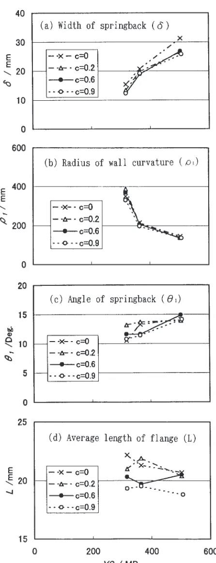
The influences of the measured sections and clearance on the width of springback () are shown in Fig.5. The influences of yield stress (YS) and clearance on, sidewall curvature (1), angle of springback (1) and average flange
length (L) are shown in Fig.6. From these figures, the following conclusions were reached:
Fig. 2 Schematic illustration of forming process of bumper model.
Fig. 3 Photograghs of forming and formed bumper model (Released condition).
Fig. 4 3-D measured items of formed shape.
[image:2.595.109.491.69.198.2] [image:2.595.306.549.237.352.2] [image:2.595.75.262.442.758.2] [image:2.595.325.529.611.770.2]‹ As the width of springback is nearly the same for the sections of the front edge (a), middle (b) and tail edge (c), the authors adopted the 2-D FEM analysis instead of the 3-D analysis.
› For the width of springback and sidewall curvature, the influence ofYSis large, but the influence of clearance (c) is small.
fi For the angle of springback and average flange length,
the influence of bothYSand clearance (c) is compara-tively small.
4. FEM Analysis
4.1 Analysis method
Using the FEM code MARC for static implicit analysis, 2-D elastic plastic analysis was conducted and the numerical results were compared with the experimental results. In the code, von Mises’ yield criterion was assumed, Young’s modulus was 206 GPa, Poisson’s ratio was 0.3, and the coefficient of friction between tool and material was assumed to be zero. The work-hardening properties of the materials were expressed by eq. (3) of Swift-type approximation, which are shown in Fig.7. Stress-strain curves of materials A to C in Fig.7were obtained by a tensile test of materials in the rolling direction shown in Table 1. A1 is a virtual material with work hardening assumed to be high and YS assumed to be low, similar to material A. Numerical results and a discussion of A1 are given in the following section. The dimensions of the punch and dies were the same as those of the experimental tools used. The blank was divided into five equal parts (0.28 mm thick) in the thickness direction. In the width direction, the blank was divided into 500 equal parts (0.6-mm width) with a distortion element expressed by four nodal points under the condition of plane strain. Simulated forming was conducted first by applying 4.12-MPa back pressure, followed by punching, and then the applied load was removed in order of back pressure, punch and die. The clearance was 0.6 mm.
¼Kð"oþ"pÞn ð3Þ
4.2 Numerical results
Analyzed shapes of material A under forming and released conditions are shown in Fig.8. When the forming height ranged from 0–70 mm, the formed shape of the cross section coincided with the experimental results in Fig.3. At a forming height of 70 mm, springback is recognized by a variation between the loaded shape and the released shape. Fig. 6 Influences of yield stress (YS) and clearance (c) on springback.
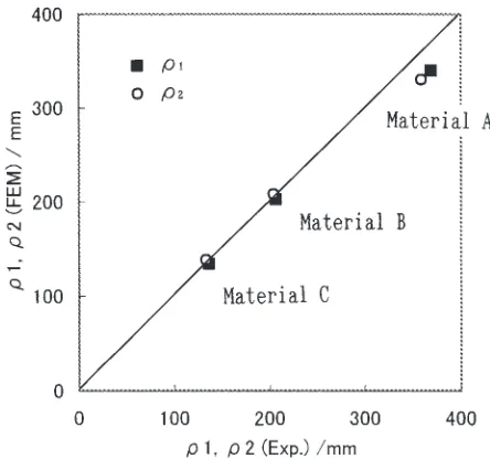
[image:3.595.57.280.63.644.2] [image:3.595.323.527.70.260.2]Figures9and10show the comparisons between the shapes analyzed by FEM and the measured shapes of materials A and C, respectively. In these figures, the thicknesses of the analyzed shapes are drawn larger than the actual thicknesses. Figures11and12show the comparison of wall curvature1, 2 and width of springback between FEM analysis and
measured shapes, respectively. From these results, the FEM analysis coincides well with the experiments.
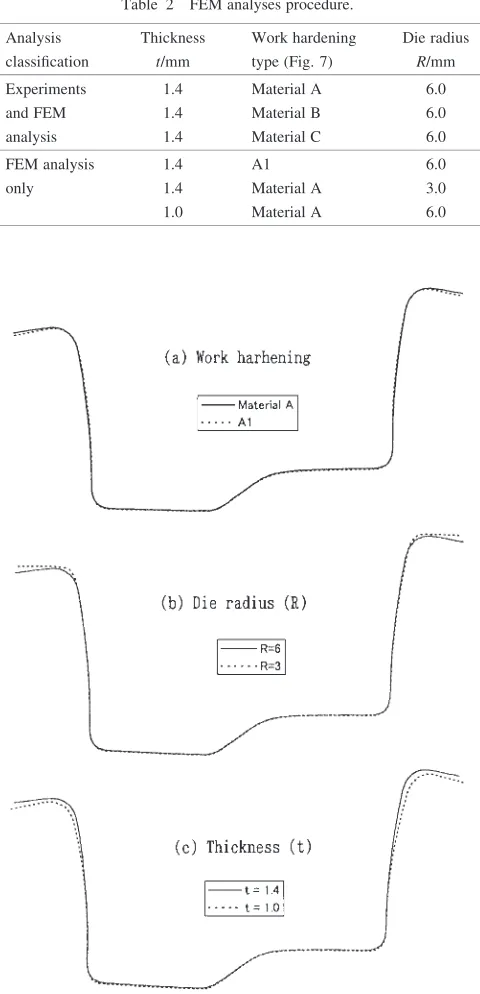
5. Influence of Material Properties and Forming Con-ditions
As mentioned in the previous section, the numerical results obtained by FEM analysis coincided well with the results of the experiments. To clarify the influence of material proper-ties and forming conditions by experiments, simulation by FEM analysis was conducted in order to investigate work Fig. 8 FEM analysis of forming and formed shape (Material A).
[image:4.595.57.281.77.264.2]Fig. 9 Experimental and FEM analysis of formed shape (Matrial A).
[image:4.595.77.264.298.520.2]Fig. 10 Experimental and FEM analysis of formed shape (Matrial C).
Fig. 11 Correlation of experimental (Exp) and FEM analysis on radius of wall curvature (1,2).
[image:4.595.314.536.319.527.2] [image:4.595.59.278.550.758.2]automobile panels, including deep drawing.
6. Conclusions
A forming experiment of a bumper model was conducted, and the following conclusions were obtained by comparing the actual springback shape measured with a 3-D measuring machine and the simulation results calculated by the static implicit FEM.
(1) There is practically no difference in the actual shape between the central section and the two ends of the bumper model.
(2) The yield stress (YS) of the material has a large effect on the width of springback and on the radius of wall curvature, but the clearance has a comparatively small effect.
(3) Regarding the formed shape during intermediate pro-cessing and the shape of springback, the actual shape analyzed by 3-D measurement coincides well with the simulated one by FEM analysis, which shows the effectiveness of using FEM analysis.
(4) The simulation results by FEM analysis regarding the effects of material properties and forming conditions show thatYShas a larger effect on springback than on the work hardening of the material, and that springback increases as the thickness of the material decreases.
REFERENCES
1) Special issues of shape fix-ability of automobile panels: Journal of JSTP24–275 (1983).
2) Special issues of formability of high strength steel sheets for automobile use: Journal of JSTP35–404 (1994).
3) Y. Nagai: Journal of JSTP38–442 (1997) 967–971. 4) Y. Tozawa: Journal of JSTP18–202 (1977) 953–962. 5) A. Makinouchi: Journal of JSTP31–354 (1991) 870–874.
6) M. Urabe and Y. Yamasaki: 51st Conference of JSTP (2000) 123–124. 7) T. Kuwabara, S. Masaki and S. Takahashi: 51st Conference of JSTP
(2000) 121–122.
8) T. Uemori, T. Okada and F. Yoshida: 51st Conference of JSTP (2000) 115–116.
9) S. Sui and A. Makinouchi: 51st Conference of JSTP (2000) 183–184. 10) N. Yamamura, T. Kuwabara and A. Makinouchi: 51st Conference of
JSTP (2000) 185–186. Analysis Thickness Work hardening Die radius
classification t/mm type (Fig.7) R/mm
Experiments 1.4 Material A 6.0 and FEM 1.4 Material B 6.0 analysis 1.4 Material C 6.0
FEM analysis 1.4 A1 6.0
only 1.4 Material A 3.0
1.0 Material A 6.0
[image:5.595.50.290.182.679.2]