DEVELOPING
A
PATH
PLANNING
ALGORITHM
TO
ENHANCE
THE
PERFORMANCE
OF
A
SOFT
ROBOTIC
ENDOSCOPE
J.W. (Jornt) Lageveen
MSC ASSIGNMENT
Committee:
prof. dr. ir. G.J.M. Krijnen
dr. ir. M. Abayazid
dr. ir. H. Naghibi Beidokhti
dr. C. Brune
October, 2019
044RaM2019
Robotics and Mechatronics
iii
Summary
Current interest in Minimal Invasive Surgery (MIS) and Natural Orifice Transluminal Endo-scopic Surgery (NOTES) applications stimulates the development of surgical robotics applica-tions. However, a current limitation of the technology at hand is the lack off flexible tools that are able to manipulate during surgical operation, due to their lack off stiffness capabilities. This provides a potential barrier for further improvements. A possible solution for this problem can be found inspired by nature, in the shape of soft robotics. Soft robotics has potential to com-bine flexible and stiff properties, making it possible to follow complex trajectories where high flexibility is needed, as well as being able to use stiff properties to for example properly exert the necessary amount of force during operation.
In this study, the control of a multi-module endoscope was investigated by means of using path planning. The research goal included the development of a path planning algorithm that would increase the safety of operation, while taking into account the physical limitations of the soft robotic endoscope. Objectives were to avoid collisions and to stay away from the boundaries of the insertion environment as much as possible. Other factors that were considered are op-erating speed and the amount of inserted pressure.
Due to the limited bending performance of the previous design, a new design was chosen and fabricated. The new module was made of EcoFlex 0030 and implemented outer sheathing. Knowledge has been obtained regarding the bending capabilities of the endoscopic modules, together with the pressure-bending relation of every respective module, which were analysed during characterization experiments. A model describing the bending behaviour of the endo-scopic modules has been defined, which has been tuned using the knowledge obtained from characterization. This model, together with the endoscope module dimensions and charac-teristics found, formed a basis for the development of the path planning algorithms. A Path Planner algorithm was developed that would define a path through the environment. This al-gorithm was based on a variation of Rapidly-Exploring Random Trees (RRT*), which builds a path tree based on randomly sampled points. Using the kinematic model approximation of the soft endoscopic modules, the endoscope was simulated to follow the created path, of which the bending angle response has been documented.
The resulting angles were converted into pressures by using the defined pressubending re-lation of the endoscopic modules inside the assembly. Due to the hysteresis behaviour of the soft robotic endoscope modules, combined with the stick-slip effect of the platform on which the experiments were conducted, this pressure-bending relation was rather difficult to predict. Eventually, the average of the hysteresis curve of the modules was used to convert the angles to pressures, which would be inserted in the path planning experiment. To verify the perform-ance of the path planned endoscope, the performperform-ance was compared to manual insertion of the endoscope.
Due to the open loop nature of the path planned control of the soft robotic endoscope inside the two selected scenarios, combined with several factors which affected the eventual perform-ance such as stick-slip phenomena, hysteresis behaviour, and inaccuracies in mapping pres-sures to bending responses, it was difficult to perform the insertion inside the environments using path planning. Manual experiments provided a solid claim for the need of an alternative for manual control, but without proper control feedback it is difficult to realize the desired path planned behaviour.
v
Acknowledgements
This work would not have been possible without the support of the following people, both for my work and for me personally.
I would like to thank my daily supervisors Momen Abayazid and Hamid Naghibi, for their guid-ance and support throughout the study. Thank you for all the lessons and fruitful discussions. Furthermore, I would like to thank Yoeko Mak, who has fulfilled many roles throughout my study, both as mentor and teacher as well as fellow student and friend. Thank you for always being there when I needed help. I would like to thank my fellow colleagues from the office as well, for all the good times and for all the good suggestions throughout the process. The team always supported me You made the graduation process bearable for me and I will always cher-ish the moments together. A big thanks to Geert Folkertsma, Marcel Welleweerd and Vincent Groenhuis, for thinking with me during the most crucial moments. Without them, several im-portant steps would not be developed as far as they are now. Furthermore, I would like to thank Teun van der Molen, Alexander Dijkshoorn, Jeroen van Dorp, Jan Lenssen and Yoeko Mak, as friends at work who gave their time to think with me and bringing me further up the road. A special thanks to Jan Lenssen, as he has been my mentor throughout the fabrication and design process, and has built an infrastructure on which lots of us could continue their work upon.
Furthermore, there are countless people behind the scenes that were just as important for the process, as they kept me standing and supported me in every phase and mental state along the way. Therefore, I would like to thank my family. They always has been the most supportive persons and even though they might not always get the topics I am working on, they would still always be there to provide help. Thank you for all the love and support, throughout all stages of my life. I could not have been more fortunate. Although my family was a big support throughout my thesis, the biggest support throughout this thesis has been my girlfriend, who basically had suffered the most from my work. She found a broken man coming home late more times than I could count, listened to me, motivated me and polished me up again. Thank you very much for being in my life and for making it so enjoyable. Furthermore, I have to thank the fraternity GTD, for bringing so much joy to these desperate times. Next to that, a big thanks to my old board mates, who always were there for me. Especially Dave Vogel, who always was ready to help. A big thanks to my house, who understood my situation and spared me in times where I had come home very late a little too often. Sorry for that. Furthermore, thanks to the ’Koffiebois’, for forcing me to have a normal life and let me have an enjoyable break every once in a while.
Next to that, I would like to thank the technicians, who helped me and thought with me during many steps in development, with special thanks to Sander Smits and Henny Kuipers. I would like to thank Jolanda Boelema-Kaufmann for her endless care and support throughout the year, bringing me relief in stressful moments.
vii
Contents
1 Introduction 1
1.1 Soft Robotics . . . 1
1.2 Path Planning . . . 2
1.3 Research Goal . . . 3
1.4 Contribution . . . 4
2 Theoretical Background 5 2.1 Soft Pneumatic Endoscope Modules . . . 5
2.2 Rapidly Exploring Random Trees . . . 6
3 Study Approach 10 3.1 Assumptions . . . 10
3.2 System Overview . . . 10
4 Design and Characterization Procedure 13 4.1 Module Design Choice . . . 13
4.2 Bending Characterization Single Modules . . . 15
4.3 Characterization of Endoscope Modules in Environment . . . 16
4.4 Angle to Pressure Conversion . . . 20
4.5 Discussion . . . 22
4.6 Conclusion . . . 25
5 Kinematic Model: Bending Module 27 5.1 Constant Curvature Model . . . 27
5.2 Integrating Modified Model . . . 28
5.3 Comparison Models and Physical Module . . . 29
5.4 Discussion . . . 29
5.5 Conclusion . . . 31
6 Path Planning Algorithms 32 6.1 Path Planner . . . 32
6.2 Endoscope Kinematic Planner . . . 36
6.3 Path Planned Endoscopic Pressures . . . 45
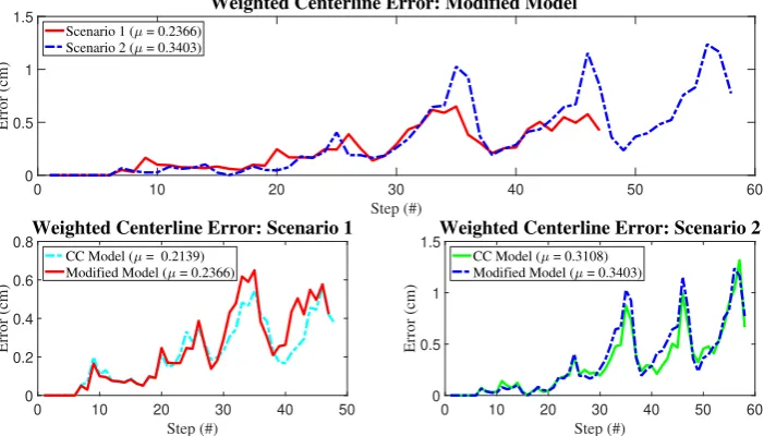
6.4 Comparison Weighted Centerline Error . . . 46
6.5 Discussion . . . 48
6.6 Conclusion . . . 49
7.1 Manual Insertion Experiment . . . 51
7.2 Path Planned experiment . . . 53
7.3 Results Evaluation of Path Planner Performance . . . 54
7.4 Discussion . . . 58
7.5 Conclusion . . . 62
8 Discussion 63 9 Conclusion 65 10 Future Recommendations 67 10.1 Current Behaviour Mismatch . . . 67
10.2 Algorithm . . . 67
10.3 Imaging Connection . . . 67
10.4 Module Design . . . 67
10.5 Actuation . . . 68
10.6 Interaction . . . 68
10.7 Medical Knowledge . . . 69
Bibliography 70 Appendix A: Literature review 75 A.1 Abstract . . . 75
A.2 Introduction . . . 75
A.3 Conventional Path Planning Algorithms . . . 75
A.4 Trajectory planning algorithms . . . 78
A.5 Novel Path Planning Approaches . . . 78
A.6 Alternative methods for autonomous motion . . . 79
A.7 Virtual Endoscopic Path Planning . . . 80
A.8 Potential for Endoscopic Operations . . . 81
A.9 Discussion . . . 82
A.10 Conclusion . . . 82
Appendix B: Commercial Endoscopes 83 Appendix C: Fabrication process 85 C.1 Design description . . . 85
C.2 Manufacturing the chambers . . . 85
C.3 Pouring the first layer: EcoFlex 0030 . . . 86
C.4 Adding the top layer: DragonSkin 10 . . . 88
CONTENTS ix
Appendix D: Data Analysis Characterization - Single Module 90
Appendix E: Data Analysis Characterization in Quaternions - Endoscope Modules 95
E.1 The Principle of Defining Bending Angle . . . 95
E.2 Post-Processing Angle Data . . . 95
Appendix F: Hysteresis Results for Inner Sheath Design 97
F.1 Results . . . 97
F.2 Discussion . . . 97
F.3 Conclusion . . . 98
Appendix G: Malfunction and Maintenance 99
Appendix H: Extensive Information Developed RRT* 101
Appendix I: Image Processing of the Experiment Data 104
I.1 Procedure . . . 104
I.2 Discussion . . . 106
Appendix J: Results Questionnaire 108
1
1 Introduction
An important area of interest in current surgical operations is the field of Minimally Invasive Surgery (MIS) (Vitiello et al., 2013). This type of surgery started to develop in the 1960s and is currently a widely used term in the medical field. MIS procedures have several benefits, such as scar reduction and decreased recovery time (Gomes, 2011). One of the aspects that enabled the development of MIS is the field of surgical robotics. With the increase in popularity of MIS tech-nology, improvements of the current technology were requested, after which developments in the area of surgical robotics followed. (Gomes, 2011)
Examples of MIS operations are laparoscopic surgery and Natural Orifice Transluminal En-doscopic Surgery (NOTES) (Vitiello et al., 2013)(Gomes, 2011). Laparoscopic surgery (Garry, 2006) is a technique that is able to substitute a large incision by making use of multiple small incisions. Using multiple small tools and with the help of proper vision of the inside, this tech-nique aims to reduce trauma. NOTES (Voermans et al., 2007) is an endoscopic type of surgery that focuses on surgery performed using only the natural orifices to enter the human body, such as the mouth and anus. A great benefit of this technique is that no incision has to be made at all to be able to perform surgery.(Voermans et al., 2007)
As technologies are being developed, their limitations also emerge. For both techniques, it is mentioned that current operation has limited flexibility (Vitiello et al., 2013)(Cianchetti, 2013). It has been stated that there is a need for so-called flexible robotics that are able to meet the de-mands of Flexible Access Surgery (FAS), which implies operating through openings that are not optimally aligned and are complex to manoeuvre through (Vitiello et al., 2013). Other articles also address the performance problem when dealing with rigidity in instruments used (Vyas et al., 2011). In this case, this is focused on laparo-endoscopic single-site surgery (LESS) and NOTES. The authors also mention the need for flexible systems to reduce this problem (Vyas et al., 2011). However, a problem that occurs with flexible structures is that they lack the pos-sibility of exerting proper force upon the environment (Loeve et al., 2010), which limits their functioning during operation.
A new and interesting development that might overcome the dilemma between flexible and rigid endoscopes is the development of soft robotics. The area of soft robotics (Trivedi et al., 2008) has shown characteristics that overcome mobility limitations. Stiffness methods can be implemented into the soft material, creating a combination of rigidity and flexibility (Gifari, 2018). This is why soft robotics could be considered a good candidate in further development of this field of MIS applications.
1.1 Soft Robotics
Soft robotics is an upcoming technological development, inspired by natural phenomena such as the physical properties of animals (Trivedi et al., 2008)(Kim et al., 2013). Examples of animals (Kim et al., 2013) possessing soft structures that inspired robotic devices are worms, octopuses and caterpillars.
Benefits of the implementation of soft robotics (Kim et al., 2013) are, among others, a more safe interaction with the environment. An example of this is the contact with human tissue during surgery. Additionally, an article mentioned that the soft components would be cheaper com-pared to the conventional technology. (Kim et al., 2013) Furthermore, it has been mentioned that the use of soft material could serve as a substitute for metal parts, making it possible to operate the system in MRI environments. (Fra´s et al., 2015)
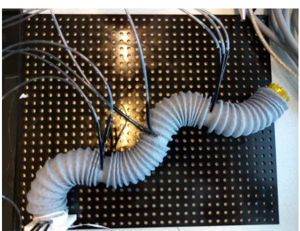
Figure 1.1:Representation of the soft robotic endoscope from the current study, which behaves rather similar to a tentacle of the octopus.
a certain trajectory through the environment, while the possibility of gaining rigid properties enables the operator to exert a higher amount of force during interaction with the environment when manipulating. (Fra´s et al., 2015)
Soft robotics can be implemented in various scenarios, of which the medical field (Kim et al., 2013) is one. It has been mentioned that, due to less chance of trauma when operating, the soft robotic technology could be suitable for MIS applications. Other applications for soft robotics mentioned are, for example, research and rescue operations, as well as cases where they can be assisting humans. (Kim et al., 2013)
As this area of soft robotics could provide promising steps to improve MIS performance, the research group of Robotics & Mechatronics at the University of Twente started a project to ex-plore the possibilities of soft robotic technology (Gifari, 2018)(Lenssen, 2019). The currently made design has been inspired by a soft robotic application called the STIFF-FLOP (STI, 2015). This system is inspired by the physical functioning of the arms of an octopus (STI, 2015). The resemblance can be seen in the current endoscope as well, indicated in Figure 1.1. The soft robot is named MOLLUSC, which stands for Multi-LeveL Stiffness Controllable robot (Gifari, 2018). Another iteration followed the development of the MOLLUSC (Lenssen, 2019), although stiffening properties were left out, and the main focus was aimed at scaling the module design down. Next to the design aspect, attention was paid to the kinematic representation of the endoscope module behaviour (Lenssen, 2019) (Jansen, 2018).
1.2 Path Planning
As the soft robotic endoscope is being developed, it is essential to think about ways to control and steer the endoscope for application purposes. When regarding endoscopic operations, the target is often not close to the insertion site, which results in the endoscope having to cover a certain distance through a passage consisting of hard or deformable tissues. With commercial flexible endoscopes only having a controllable tip, this would make it rather difficult to avoid any interactions. The combination of modules into a soft robotic endoscope would enable to have full control over the whole endoscope structure.
reas-CHAPTER 1. INTRODUCTION 3
onable speed, with the least dissection required and the least risk of damage to the tissues around the endoscope. One of the important criteria for the path that should be taken into account is the safety of the patient. The created path should avoid the risk of damaging tissue as much as possible. Another measure that has to be taken into account regarding safety is the amount of bending that is performed by the endoscope. Reducing the amount of bending results in a reduced use of pressure, which decreases the risk of damaging the endoscope and potentially harming the patient. Other criteria that have to be taken into account are the speed and stability of the endoscopic operation. Operating the endoscope should occur at reasonable speed. The current soft robotic endoscope design might suffer from speed limitations during operation, due to the fact that multiple modules have to be actuated accordingly. This should be taken into account as well.
A path planning algorithm will be developed, which takes into account safety measures re-garding pressure, maximum bending, and position in the environment, as well as general con-straints of the soft robotic endoscope.
1.3 Research Goal
This research focusses on the development of a path planning algorithm specified for our soft robotic endoscope, to optimize reaching the target area, while considering safety and physical boundaries of the soft robotic endoscope. The main research question can be stated as follows:
How can a path planning algorithm be developed for soft robotic endoscopes, taking into account safety and the physical boundaries of the system?
Potential sub-questions are:
1. Which path planning algorithm would suit the steering of a soft robotic endoscope?
2. What bending characteristics can be found regarding the endoscope module perform-ance?
3. In what way can the path planning algorithm(s) be coupled to the actual bending char-acteristics of the endoscope modules?
4. Which approaches can be used in combination with the path planning algorithm to make a safe path that can be followed by the soft robotic endoscope?
5. What setup can used to be able to experimentally test the developed path planning al-gorithm?
6. How would the path planning algorithm perform compared to manual operation in terms of safety and speed?
The field of endoscopic MIS and NOTES is used as target application. To specify our case in more detail, colonoscopy is chosen as test case. The choice of this application is made based on the current size of our endoscope design, as this is an operation which would be deemed most possible to use. However, this study can also be of use when considering other endoscope applications, when regarding this type of soft robotic endoscope.
and 9 will address the discussion and conclusions regarding this research. Finally, recommend-ations for future research are given.
1.4 Contribution
This study will provide new insights in the use of path planning for soft robotic endoscope ac-tuation. To the author’s knowledge, using path planning to control a soft robotic endoscope has not yet been researched before, although steps are made in the area of combining path planning with continuum robotic endoscopes (Gao et al., 2019) (Chen et al., 2014).
5
2 Theoretical Background
This chapter will briefly describe the basic working principle of the soft pneumatic endoscope modules. Furthermore, this chapter will give background information regarding the path plan-ning algorithm chosen for this study, together with some of the mentioned benefits found in literature and applications related to the current research. A more general description of path planning is mentioned in the Appendix (Chapter A). The chapter also concerns sub-question 1.
2.1 Soft Pneumatic Endoscope Modules
Soft Pneumatic Actuation has been under study at the Robotics and Mechatronics group for quite a while, as it has promising features for future applications. One application was the sim-ulation of the movement of the liver using soft pneumatic actuators (van Dorp, 2019). In this study, to focus was on developing a setup that could mimic respiratory motion and, if possible, an inclusion of the heartbeat as well. Other studies use the soft pneumatic actuation integrated in orthoses, to stimulate correct positioning. A rather big branch in Soft Robotics research fo-cusses on the development of a soft robotic endoscope, of which the design has been under study by Gifari(Gifari, 2018) and Lenssen (Lenssen, 2019).
2.1.1 Bending Principle
The main principle of the pneumatic endoscope module is bending through expansion of the actuated chambers, which is described well by the work of Naghibi et al. (Naghibi et al., 2019) and can be seen in Figure 2.1.
Applying pressure to the chambers causes the chambers to expand, resulting in a bending of the module towards the opposite direction of the chamber. Multiple chambers in one module can be actuated together, forming a resultant bending or, when complete bending cancella-tion occurs, lengthening of the modules. It is desired to limit the expansion of the chambers in radial direction as much as possible, as this limits bending performance. Therefore, several sheathing techniques have been treated. The material used for these modules is often a
[image:15.595.179.419.534.741.2]bination of EcoFlex 0050 and Dragon Skin 10, both silicone materials that can be utilized in for example the fabrication of face masks (Smooth-On, -). Due to a combination of high tensile strength (around 2.17 MPa (Smooth-On, -)) and high compliance, the material is suitable for this bending application.
2.1.2 Previous Studies
Gifari (Gifari, 2018) worked on the characterization and stiffening of a soft robotic endoscope module, based on the work of the STIFF-FLOP (STI, 2015). The study was focussed on one module that was made from EcoFlex 0050, having a cover of Dragon Skin 10. The module was surrounded by an outer sheath, made from computer cable housing, which was manipulated to facilitate proper bending. The same computer cable housing has been used in other stud-ies (van Dorp, 2019) to facilitate pneumatic actuators, as they properly constrain expansion in radial direction. The design had four chambers, placed with equal spacing from each other. Gifari focussed as well on the integration of vacuum chambers in combination with pressure chambers, to facilitate stiffening (Gifari, 2018). A hole was made in the middle of the module, so potential tools such as a camera could be inserted.
Lenssen (Lenssen, 2019) developed the newest version of the soft robotic endoscope modules. The main focus of the study was the scalability of the endoscopic modules. The modules were made out of EcoFlex 0050 with an additional layer of Dragon Skin 10 and had the dimensions of 50 mm in height and 25 mm in diameter. The design of such a module consisted of three chambers, surrounded by wiring to restrict the chamber from expanding in the radial direction, instead of using an outer sheath. Lenssen also created a central tube for the tooling, but left the stiffening mechanism out of the design. From his work, it was concluded that increasing the number of chambers to four would not increase the number of degrees of freedom, compared to three chambers. Furthermore, it was mentioned that using three chambers would reduce the number of tubing and potential control infrastructure. (Lenssen, 2019)
This study will continue based on the work of Lenssen (Lenssen, 2019). However, the technique of surrounding the chambers by means of wire severely limited bending capabilities, stressing the need for an alternative design with more bending.
2.2 Rapidly Exploring Random Trees
This section treats the background theory behind the Rapidly-Exploring Random Trees (RRT) algorithm, which will be used throughout the study. The following sections contain a descrip-tion of the algorithm, the working principle, several applicadescrip-tions making use of the algorithm, and some of the modifications of the algorithm found in literature.
2.2.1 Description
RRT is a path planning algorithm which can be classified under Sampling Based Planners (SBP) (Noreen et al., 2016a). SBP algorithms work by means of creating randomly sampled points in order to grow and propagate. The earliest mentioning of the RRT algorithm was by LaValle in 1998 (LaValle, 1998). He proposed this algorithm as an alternative to Probabilistic Roadmaps (PRM) for situations in which non-holonomic constraints occur.
CHAPTER 2. THEORETICAL BACKGROUND 7
The RRT has shown to be rather fast in computation (Abayazid et al., 2014), making it suit-able for on-line path planning approaches where the path has to be updated throughout the trajectory.
Next to being able to cover an environment in a brief amount of time, it is also mentioned that RRT can take into account dynamic environments (Noreen et al., 2016b) and non-holonomic constraints (Noreen et al., 2016b)(LaValle, 1998). The article of Noreen et al. (Noreen et al., 2016b) mentions the benefits of SBP, such as low computation cost and good performance for higher dimensional and complex problems.
Next to that, Noreen et al. (Noreen et al., 2016a) indicated the characteristic of SBP al-gorithms to be probabilistic complete, which is also mentioned about RRT alal-gorithms by LaValle (LaValle, 1998), under general conditions. This implies that, if there exists a path solu-tion, the algorithm will eventually find it, given infinite time (LaValle and Kuffner Jr, 2001).
Furthermore, the RRT algorithm is promoted as being a relatively simple algorithm, which can easily be integrated into other planning systems (LaValle, 1998). Next to that, a beneficial aspect that was stated is the ease of use, as it does not need any additional control or steering to move towards the target. This makes for a rather stand-alone algorithm. (LaValle, 1998)
The work of Elbanhawi et al. (Elbanhawi and Simic, 2014) describes many phenomena consid-ering RRT and variations on the algorithm.
2.2.2 Procedure
Several variations on the RRT algorithm exist, ranging from forward search to backwards search and even bidirectional growth of the trees (LaValle, 2006). An example of bi-directional growth can be found in the article by LaValle et al. (LaValle and Kuffner Jr, 2001), depicting a simulation of the path planning algorithm.
Furthermore, several varieties of RRT exist in terms of the moment the algorithm finishes its computation. Some algorithms stop as soon as one branch of the grown tree reaches from the initial starting point up to the target. Others have a predefined number of iterations that have to be completed, after which the best possible path is selected.
Regarding the general form, which has been proposed by LaValle (LaValle, 1998), the steps of the algorithm can be described in the following manner. Each iteration, a random point is sampled. Based on the distance of this point compared to the other point in the tree, the nearest tree point selected. From this point, a feasible input is chosen, which minimizes the distance between the two points. Before connecting, a check is performed to verify no collision occurs during connection. Then, the new point is added to the tree. Besides storing the coordinates of this new point, the input necessary to reach this point is also stored. (LaValle, 1998)
Figure 2.2:Two of the scenarios that can occur after choosing the closest point in the tree with respect
to the randomly sampled point.A)Point found inside specified boundary region, direct connection can
be made. B)Randomly sampled point found outside of specified region from the selected point of the
tree, causing a new point to be created on the path towards the random point, on boundary of the point. Image inspired by the representation in the article of Blanco et al. (Blanco et al., 2015).
2.2.3 Applications
The application direction of the RRT algorithm is rather broad, although one of the main ap-plications seems to be that of (autonomous) vehicles. Examples can be found in (Blanco et al., 2015) (Kuwata et al., 2008)(Liu, 2017) (Han et al., 2011) (Katrakazas et al., 2015). Furthermore, Liu addresses the autonomous control of Unmanned Aerial Vehicles (UAV’s) (Liu, 2017).
The use of the RRT algorithm as a path planner has not yet been utilized for endoscopic pro-cedures to the writers knowledge. However, the principle can be found in the area of needle steering (Xu et al., 2008) (Patil and Alterovitz, 2010) (Abayazid et al., 2014).
The work of Xu et al. (Xu et al., 2008) focusses on the development of a path planner than could plan a path for the steerable needle throughout an environment containing obstacles. The art-icle mentions the difficulty that arises with the bevel tip design of the needle, bringing forth holonomic constraints. It also stated the potential for RRT algorithms to cope with non-holonomic constraints. (Xu et al., 2008)
Patil et al. (Patil and Alterovitz, 2010) developed an RRT algorithm that could produce results with a high speed for a steerable needle inside an environment containing obstacles, which makes it suitable for potential future on-line path planning applications. It would then be pos-sible to control the needle throughout the environment based on imaging techniques, such as MRI. (Patil and Alterovitz, 2010) The study by Abayazid et al. (Abayazid et al., 2014) uses RRT as a method to quickly develop paths throughout the trajectory of the bevel-tip needle. It enables the combination of ultrasound images with the path planner. This allows for compensation of movements by the target, the obstacles, or both. (Abayazid et al., 2014)
The study of Park et al.(Park et al., 2015) used the RRT algorithm to develop motion trajectories for the robot arm holding the endoscopic tool for a Da Vinci surgical robot.
2.2.4 Modifications to the algorithm
CHAPTER 2. THEORETICAL BACKGROUND 9
with narrow passages (Rilk et al., 2009). To tackle these limitations and to improve upon the stated conditions, several modifications can be applied.
As the sampling of random points is one of the reasons why limitations occur within this al-gorithm, several methods are proposed to increase sampling efficiency. The article of Patil et al. (Patil and Alterovitz, 2010) makes use of a reachability guided sampling heuristic, which only takes into account random points that are computed within range of the current tree. Another successful way to reduce the number of samples is to reject all the random samples that are positioned in the obstacle regions, as also is mentioned by Noreen et al. (Noreen et al., 2016b). These two methods reduce the amount of computation to only the most relevant cases.
To reach the target earlier, one can choose to define a target region instead of a stand-alone target coordinate, which would speed up the process. The so-called goal region was also found in the article by Alterovitz et al. (Alterovitz et al., 2011). Another approach is implemented by Patil et al. (Patil and Alterovitz, 2010), which mentions the use of a goal bias towards the target region. This goal bias supports the growth of the tree towards the target.
RRT* is a version of RRT which takes into account potential nearest neighbours that have a lower distance cost compared to the originally computed path (Noreen et al., 2016b). This al-gorithm is very comparable to RRT, but the additional nearest neighbour cost computation makes the eventual result more optimal in terms of distance cost.
Rapidly-Exploring Roadmaps (RRM) (Alterovitz et al., 2011) has some similarities with RRT*, but differ in the fact that the refinement will not occur uniformly but rather directed towards the computed goal path. In other words, the RRM algorithm only refines when the path is con-nected with the goal, saving computation effort on refinement compared to RRT*. (Alterovitz et al., 2011) The RRM method works using anω-value, which indicates the relation between exploring and refining. This refinement option is able to reach an optimal solution when time goes to infinity. The algorithm was tested upon a moving point robot and a concentric tube robot for medical purposes (Alterovitz et al., 2011).
Other work (Falatehan, 2012) mentioned the RG-RRT algorithm, or the Reachability Guided RRT, which possesses a section that checks whether a randomly generated sample can be reached by a section of the tree. Not-reachable samples will be discarded. The standard RRT algorithm gets less efficient when regarding rather complex environments, since fewer points are found suitable for use and more points will eventually be initialized, asking for more com-putational power. This alternative algorithm can reduce the amount of computation by simply reducing the number of potential options. (Falatehan, 2012)
Noreen et al. (Noreen et al., 2016a) address the differences of RRT and RRT* with respect to yet another variation; RRT*-Smart, which incorporates sampling that is biased towards a defined beacon region as well as utilizing a biasing ratio that can be used for a smarter exploration of the environment. (Noreen et al., 2016a)
2.2.5 Application to this study
3 Study Approach
In earlier chapters, the outline of this study has been presented, as well as some theoretical background on the material that will be implemented during this study. This chapter will dis-cuss the main assumptions made during research, together with an overview of the different stages treated throughout this study, as well as the relation between the different stages.
3.1 Assumptions
This study deals with several simplifications and assumptions made throughout the process. Although the eventual target application will be based on operation in a 3D space, the initial focus of this study is only considering a 2D environment, which simplifies both planning and actuation.
Next to that, the current study deals with a static environment as a start, implying that the sur-roundings remain the same, while keeping in mind that this assumption does not hold with respect to the physical scenario. The human body is rather dynamic, possessing deformable tissues and suffering from the effects of gravity, breathing and beating of the heart, which all contribute to movement of the organs. This makes for many factors to consider. However, for the sake of simplification, the initial work will consider a static environment.
Furthermore, as the focus of this study is mainly on the working principle of the algorithms and the use of the physical endoscope in combination with this software, the accurate representa-tion of the used environment is currently deemed of less importance. The used environments are abstract representations of bending scenarios that might occur during operation, but do not resemble a realistic scenario in such.
In general, the RRT-algorithm has the ability to provide an efficient resulting path for environ-ments in the human body that could have complicated branching structures, which normally would make it difficult to define a path. Although the more complex scenarios would shine more light upon the benefits of using RRT, the main objective was to define the contribution to steering the soft robotic endoscope, which is why more complicated branching has been left out for now.
3.2 System Overview
The steps taken throughout this study to get from a specified environment towards the eventual pressures are represented in the Figure 3.1. The big phases throughout the study can be divided into design and characterization, modelling, path planning implementation, angle to pressure conversion, and eventually the final experiments to compare path planning with manual in-sertion. These are depicted with letters in Figure 3.1, in order of occurrence throughout the report.
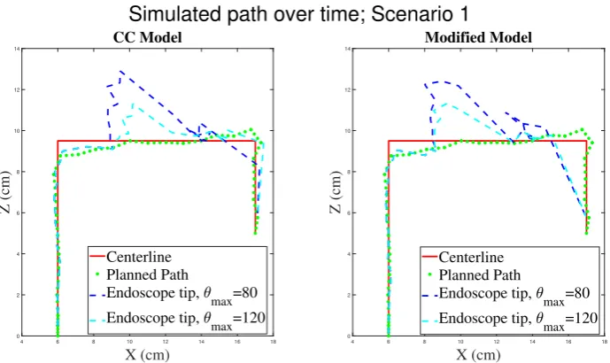
It should be mentioned that the process contained iteration, as for example a modification of the model leads to changes in the algorithms as well. A distinction between the previous model and the modified model will be elaborated upon in the chapter concerning the model (Chapter 5) and the chapter describing the algorithm (Chapter 6). The following section shortly describes the process throughout the report (with exception of Stage D, which is included in the design and characterization chapter, Chapter 4).
3.2.1 Layout of Procedure
CHAPTER 3. STUDY APPROACH 11
E. Verification of Endoscopic Behavior in Environment
C1. Path Planner A1. Design & Fabrication
A2. Characterization & Assembly C2. Path Tracker
D. Pressure Conversion B. Model
4. Path coordinates (x,z) 1. Endoscopic
Modules
6. Pressure vs. Bending (bar vs. degrees)
8. Necessary Pressures (bar)
7. Angles (degrees)
5. Module Kinematics
2. Bending limit + dimensions
3. Bending Behaviour
Figure 3.1:A schematic representation of the sections that are treated throughout this study. Here it can be seen that hardware and software are combined to develop a complete system, which will be tested in a later phase.
and assembled into a soft robotic endoscope. This happens in Stage A2. After assembly, the modules were characterized in the used environment, to define their behaviour under circum-stances. The findings regarding bending limitations and endoscope module dimensions were used as criteria for the development of the path planner algorithms (Step 2), whereas the bend-ing behaviour found aided in the development of the kinematic model (Step 3). More on this in Chapter 4.
The model (Stage B) used the kinematic representation of the module considering the con-stant curvature assumption, which was found in earlier work (Jansen, 2018) based on Webster lll (Webster III and Jones, 2010). By means of experiencing module bending during character-ization, a modified model has been developed (Step 3). The model serves as a basis for the kinematic representation of the ’Path Tracker, or ’Endoscope Kinematic Planner’ (Stage C2). Elaboration follows in Chapter 5.
The path planning algorithms make use of this knowledge (Step 2) to define an endoscope sim-ulated response for a given setting. The Path Planner (C1), uses the RRT-algorithm to develop a path inside the pre-defined environment. The coordinates of the path are passed on (Step 4) to the Endoscope Kinematic Planner from Stage C2. The Endoscope Kinematic Planner, or ’Path Tracker’, simulates the endoscope behaviour using the defined module kinematics (Step 5), after which a resulting angle profile is given for all used modules throughout the simulation (Step 7). Chapter 6 will treat this in more detail.
13
4 Design and Characterization Procedure
In this chapter, the design choice and methods for characterization of the soft endoscopic mod-ules is described, together with the corresponding results. This corresponds to Stage A1 and A2, described in Figure 3.1 (Chapter 3). To improve bending conditions, a new module design is chosen, after which characterization was performed. A distinction is made regarding bending characterization for a single module with respect to the bending characterization of the as-sembled endoscopic modules inside the environment. Finally, the approaches for converting desired angles into required pressures for each module are treated (Stage D).
This Chapter provides the answers to sub-question 2 and a part of sub-question 3.
4.1 Module Design Choice
Initially, it was attempted to implement the module design of Lenssen (Lenssen, 2019). How-ever, one problem arose from the functional characteristics of the new design; the bending was very limited. The modules did not show bending above 30 degrees. As can be seen from Table 1 in Chapter B of the Appendix, commercial flexible endoscopes reach up to far higher bending angles. Furthermore, initial simulations pointed out that for an angle below 40 degrees, the endoscope would not be able to go through the simulated environment properly. Therefore, additional modules designs were manufactured and tested to improve the bending properties towards more commercial standards. The subsections below describe the design alternatives, experimental approach and eventual design choice.
4.1.1 Module Design Alternatives
New modules were made that are similar to the recent design of Lenssen (Lenssen, 2019), but including three extra 5 mm air holes. A hole is placed between every chamber, with the intent to improve the overall bending performance of the module. It was assumed that the reduction of material would reduce the effort necessary to bend the module in the desired direction.
Furthermore, some alternative designs were considered. At the moment, the design for the module incorporates the material EcoFlex 0050 (Smooth-On, -). To increase the flexibility of the module design, it was thought of to swap the main material for EcoFlex 0030, which is a more flexible type of silicone. The small coating inside, which is surrounding the chamber, is still made of EcoFlex 0050 for these design alternatives. This is to enhance the strength of the module chambers. Next to the idea of having an inner sheath containing the chambers, the alternative of using an outer sheath around the module was considered. The outer sheath contains the module as a whole, which initially gives more space for the chambers inside the modules to expand. All modules are coated with a layer of Dragon Skin 10 on top. Dragon Skin 10 is rather stiff compared to the Ecoflex silicone. It is placed on top to improve the strength.
These four alternatives were tested and the influence of adding three air holes was investig-ated. A more detailed description of the fabrication process can be found in Chapter C of the Appendix.
4.1.2 Bending Characterisation
eventually breaking the module. The measurements were repeated three times, except for the ones of EcoFlex 0030. The reason for this was the occurrence of rupture of two chambers in an earlier test. All experiments were recorded using a video camera. The module type, chamber number, round and applied pressure were registered on video. From the recordings, images were taken to analyse the orientation for every applied pressure step. This has been mainly performed using the software tool ImageJ (ImageJ, -). From this and from visual inspection, the bending performance could be deduced.
4.1.3 Module Design Choice
During examination of the performance of several design alternatives, it was found that the use of outer sheath modules consisting of EcoFlex 0030 material would lead to the most bending up to a certain pressure. From experiencing the performance, it was also examined that the additional holes did not give any extra bending performance.
Therefore, the further design focus of the endoscopic modules was on the outer sheath model with EcoFlex 0030 as main material. The holes are also added. From the bending performance it was found that the new module design could only handle pressure up to around half of the 1 bar mentioned earlier. This is taken into account during future characterization.
4.1.4 Module Connector Piece
To eventually connect the modules together without having too many loose wires around, the connector piece design of Lenssen (Lenssen, 2019) was altered to fit the application. This meant that all the pressure inputs of the connector were aligned on the same place, such that the pressure tubes could stay out of the way of the endoscope bending (this was present in an older version of the design of Lenssen, but is not used in his application). Rubber rings were designed on the inside of the connector inlet, such that the pressure tubes could easily be fix-ated to the connector piece without further glueing or attaching. This would simplify removal of the outer sheath and the pressure tubes, without too much hustle.
The design of the connector piece can be seen in Figure 4.1. The pressure inputs are on the same side, making it possible to separate the pressure tubes from the bending plane. The dark connector cylinders are inserted in the pressure chambers. The pressure tubes are pushed in the three holes on the side. Rubber rings inside of the holes keep the tubes in place.
CHAPTER 4. DESIGN AND CHARACTERIZATION PROCEDURE 15
4.2 Bending Characterization Single Modules
To gain more insights in the bending behaviour and repeatability of the new design, more modules were fabricated and experiments were held to further characterize the EcoFlex 0030 modules. Initially, experiments were performed with single modules, in upright position. All modules were tested with the same external sheath, such that the characteristics were mainly focussed on the module itself and were not that reliant on the position and structure of the ex-ternal sheath. The Aurora EM Tracker was used to define the bending performance. The same pressure regulators are used compared to the previous bending experiment.
In total, four modules were tested, which all had special connectors that were attached. Due to plastic deformation occurring in the sheathing, the same side was used for every experiment to not limit bending performance.
The main sequence for applying pressure starts at 0 bar, going in steps of 0.1 bar until 0.2 bar is reached. The reasons for this step size is because in the initial stage of the bending not a lot of bending can be seen. After 0.2 bar, the actual bending starts. After that, steps of 0.05 bar are performed up to a pressure of 0.55 bar. This limit is taken because after 0.55 bar the modules seem to expand rather than bend, making it less interesting in terms of bending and potentially more susceptible to damage. The respective modules were bent three times before actual measurements were performed, to detect defects and ’warm up’ the module.
Every chamber was tested five times. Every time the limit of 0.55 bar was reached, the pressure was brought back to 0 bar directly.
4.2.1 Bending Results
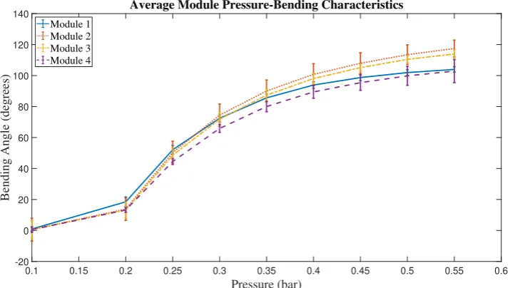
Regarding the bending of the four EcoFlex 0030 modules with outer sheath, the following res-ults were found. In Figure 4.2, an example is given of the bending performance from the three different chambers of one module. The behaviour could be considered rather similar, although the maximum deviation would almost approach 20 degrees in bending performance. Figure 4.3 shows the average pressure-bending response of four modules, containing average results of multiple rounds for every chamber inside the module. Here, it can also be deduced that the overall response of the modules is deemed rather similar.
0.1 0.15 0.2 0.25 0.3 0.35 0.4 0.45 0.5 0.55 0.6
Pressure (bar) -20
0 20 40 60 80 100 120 140
Bending Angle (degrees)
Average Module Pressure-Bending Characteristics
[image:26.595.105.463.97.299.2]Module 1 Module 2 Module 3 Module 4
Figure 4.3:Average bending performance of all modules, without additional load and in upright posi-tion. The average is taken over all chambers, for five cycles per chamber.
Elaboration upon data processing for these plots can be found in Chapter D in the Appendix.
4.3 Characterization of Endoscope Modules in Environment
To ensure that the endoscopic output pressures of the system take into account the physical characteristics of the module together with the influence of the environment upon endoscope performance, the endoscope modules had to be characterized in the environment. In this way, the effects of friction, gravitational load, load of other modules upon bending module and re-action forces of for example the pressure tubes can be related to the endoscope performance. It must be mentioned that an exact mapping of performance into a single characterization would be rather impossible, as so many factors have an influence on the position and every orienta-tion of the endoscope would result in a different characterizaorienta-tion.
For now, the experiment is kept rather basic. Every module is be actuated in a sinusoidal fash-ion, ranging from -0.55 bar up to 0.55 bar. The first module (bottom module) is fixed to the environment using a 3D printed connector piece. The EM Tracker sensor is placed on the level of the tip of the actuation module, which often resulted in a fixation of the sensor to the pres-sure tubes of the next module. At the tip, the sensor would be placed inside a 3D printed casing, which would be connected to the endoscope tip. This ensured fixed position of the sensor, as well as keeping the external sheathing in place. During this experiment, the modules below the actuated module are set to 0.1 bar of pressure on one side. This would increase the stiffness of the module, creating a more stable platform for the modules to bend on. This was in order to extract the behaviour that would be closer to a scenario during operation (during operation probably all modules will be pressurized), as well as to make a proper comparison with the fixed bottom module. Due to time constraints, it was assumed that pressurizing the modules above the actuated module would not have a big effect upon the bending performance of the actuated module, although it is imaginable that pressurizing the other modules as well would result in an improved bending.
CHAPTER 4. DESIGN AND CHARACTERIZATION PROCEDURE 17
of 0.05 bar. Four solenoid valves have been connected (MHE2-M1H-3/2G-QS-4-K) to facilitate switching between chambers (Festo, 2013). Four of the same pressure regulators compared to the previous experiment have been used to control the pressures. The experiment finished after three rounds of swinging to the left and to the right. A display of a section of the actuated pressures can be seen in Figure 4.4. Every time the zero bar is reached, the solenoid valves will switch in order to let the opposite chamber(s) be pressurized, making the endoscope module bend in opposite direction. The setup with the Aurora EM tracker can be seen in Figure 4.5, where the sensor is connected to the tip. Data is mainly processed in ways described in Chapter D and Chapter E of the Appendix.
0 500 1000 1500 2000 2500 3000 3500 4000 4500 5000
Framenumber (#) 0
0.1 0.2 0.3 0.4 0.5 0.6
Pressure (bar)
Pressure Output Arduino during Characterization
Module 1 Module 2 Module 3 Module 4
Figure 4.4:Section of the pressure output for characterization of the third module during bending char-acterization in assembly.
Figure 4.6:Average pressure-bending characteristics of all the modules, executed in assembly on a test platform. On the right, the corresponding test platform can be seen. The plots are average responses over three cycles.
4.3.1 Results Characterization Endoscope Modules in Environment
The behaviour of every module in response to the pressure approach similar to what can be seen in Figure 4.4 has been recorded using the EM Tracker disk sensor. Since the pressure for every time step of the tracker is known, a pressure-bending curve could be deducted.
The average response of the modules inside the endoscope can be seen in Figure 4.6. Here it is visible that similar pressures do not lead to similar orientations. The bending profiles seem to be dependent on historical behaviour, which will be further referred to as hysteresis behaviour. To approximate the behaviour of every endoscope module, the average of the cycles will be taken to eventually get to one hysteresis curve.
Several deductions can be made from Figure 4.6. First of all, it seems that bending perform-ance when pressurizing two chambers results in less bending compared to bending with one chamber actuated. Furthermore, it is possible to detect three zones: the ’dead zone’, the ’ex-pansion zone’ and the ’saturation zone’. The dead zone shows limited bending response for the initial pressures. After this, the bending performance sharply increases, which is followed by a saturation behaviour. Here, the further module expansion is contained. The average maximum bending performance at 0.55 bar varied from 116.6 degrees for Module 2 to 176.8 degrees for Module 1, for bending towards the right. The standard deviations from the average were found to be small, being on average around 4 degrees. Only the second module had an average stand-ard deviation of around 15 degrees.
4.3.2 Hysteresis Behaviour
This hysteresis effect was assumed to be mainly due to the contact of the endoscope with the surface, which sometimes increases the difficulty of moving the endoscope back. Therefore, other alternative methods of holding the endoscope might be considered that reduce the con-tact with the surface. Potential solutions for this could be hanging the endoscope in a vertical position, as well as using the endoscope in water.
CHAPTER 4. DESIGN AND CHARACTERIZATION PROCEDURE 19
Figure 4.7:Endoscope bending performance of Module 3, considering movement on the platform with respect to movement while in hanging orientation. Negative pressures correspond to bending towards the left. The response is an average taken over three cycles.
which the endoscope was hung upside down. In Figure 4.7, a comparison is being made between an endoscope module bending on the platform, with respect to the bending perform-ance of the same module while hanging the module upside down. Friction with respect to the platform was avoiding in this way. The results of the figure are an average response of the bending module, with respect to three cycles. The results show that the effect of hysteresis is still present.
Chapter F of the Appendix presents an experiment with a two-module inner sheath endoscope, based on the previous module design of Lenssen (Lenssen, 2019). The resulting plot is showing that also there hysteresis behaviour could be found.
4.3.3 Characterization Later Stage
Over time, the endoscope has been used very frequently, causing some of the modules to rup-ture. To ensure the endoscope would be in a proper state, a new endoscope has been formed using newly fabricated modules.
Due to several modules that broke down during characterization, the pressure was limited to maximum 0.4 bar for both directions. Pressure is being adjusted in the same fashion; steps of 0.05 bar with pauses of ten seconds in between.
As the hysteresis behaviour made it very complicated to grasp the exact performance of the endoscope module while bending, it was attempted to come up with an algorithm that would take into account the bending history of the module while bending. To be more precise, it was thought of to develop a collection of hysteresis curves based on an increased bending pressure, which would potentially grasp the approximate bending behaviour of a module after reduction of pressure. An example of the complex 3D hysteresis characterization can be found in Figure 4.8.
angles based on quaternions. The implementation was such that the resulting angles were that of the resultant bending plane. Since the bending behaviour of the endoscopic modules was not always in line with the 2D-plane of the environment platform, the use of this approach might result in a characterization that would deviate from actual performance on that plain. Therefore, for the final characterization experiments, the angles are expressed in Euler angles, preserving the response in line with the platform plane. This has been integrated in Figure 4.8.
4.4 Angle to Pressure Conversion
This section covers Stage D mentioned earlier in Chapter 3. Based on previously derived func-tions concerning the bending characterization of the endoscopic modules (Stage A2), the pres-sure values per module for each step can be derived. This is realized using the defined angles from the Endoscope Kinematic Planner of Stage C2. Several approaches were thought of to transform the generated angles into pressure outputs for the soft robotic endoscope. Main ap-proaches that were attempted are:
• Segmented curve fit
• Non-linear regression fit
• 3D mapping
• Average hysteresis fit
All approaches had their drawbacks and benefits. The main drawbacks found were related to computation complexity and implementation difficulties. The attempted approaches are treated below.
Fitting outer hysteresis curve
The fitting of the hysteresis curve throughout this study has been approached using several practices, as has been mentioned before. One of the approaches was to fit the outer curve us-ing several fits together. The hysteresis curve would be divided into eight segments, for which all polynomial functions could be defined. This would be a quite intensive approach, as every curve had to be divided and several fits had to be made. However, a reduction of segments would lead to a worse fit compared to what was done before. Furthermore, the algorithm should take into account when a switch should be made towards another part of the hyster-esis curve.
Non-linear regression fit
Another approach was the use of non-linear regression model for computation. With the use of the MATLAB function fitnlm, it was attempted to define specified functions for the upper and lower half of the hysteresis curve. The following base function was used, for which the parameters were searched by the algorithm:
F(x)=b1+b2x+b3sin(b4x+b5)+b6sin(b7x+b8) (4.1)
This, together with a set of pre-defined values, was used to create a fit across the present curves. However, during the use of the functions to represent the curve lines, it was found that the eventual pressure response after conversion was rather oscillating. After plotting the function, it was assumed that the oscillations came forth out of error in the fitting function. Therefore, the fits based on this method were skipped, and focus was put on alternative methods.
3D Mapping
re-CHAPTER 4. DESIGN AND CHARACTERIZATION PROCEDURE 21
Figure 4.8:The representation of the pressure-bending response of Module 3, for several ranges of pres-sure inputs. This time, the bending response is derived from the use of Euler angles, which are focussing on the in-plane response. In the left corner, the utilized setup is depicted. The plots are averaged over three cycles.
sponse was shown, described in Euler angles. Every pressure cycle is repeated three times, after which a pressure cycle is taken with a higher pressure limit. From the figure, it can be seen that the ends of the extremes of every curve do not seem to align properly for a lot of cases. This could simply be due to a decomposition of the resulting bending angle, which makes the con-nections not fit. However, when different hysteresis curves already separate before reaching there specified limit, it would become very difficult to retrieve on which curve corresponds to the current behaviour.
This, in combination with a limited amount of time, has lead to the decision to further simplify the characterization approach. Since following the outside of the curve also gave some diffi-culties in computation, it has been chosen to continue with the use of the middle line of the most outer hysteresis curve, which does not show angle reduction at the tip. This would result in rather simple computation, of which the offset error is inevitable.
Fitting the middle line
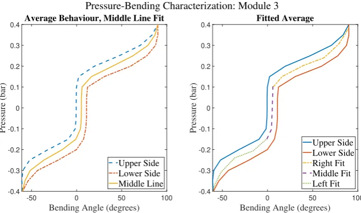
After trying several alternatives, the relatively simple fit of the centerline was deemed most con-venient, although this would introduce a certain standard deviation from the actual behaviour. The process of finding the average line was performed by means of averaging the angle per pressure step, after which the line was computed. The result of this can be seen in Figure 4.9, where the middle line is computed next to the fit of this middle line.
Pressure-Bending Characterization: Module 3
-50 0 50 100
Bending Angle (degrees)
-0.4 -0.3 -0.2 -0.1 0 0.1 0.2 0.3 0.4 Pressure (bar)
Average Behaviour, Middle Line Fit
Upper Side Lower Side Middle Line
-50 0 50 100
Bending Angle (degrees)
[image:32.595.106.460.94.303.2]-0.4 -0.3 -0.2 -0.1 0 0.1 0.2 0.3 0.4 Pressure (bar) Fitted Average Upper Side Lower Side Right Fit Middle Fit Left Fit
Figure 4.9:On the left, the fit of the middle line from the hysteresis plot is depicted, which is divided into three segments and fitted using 3rdorder polynomials, as can be seen on the right.
As can be seen in the second image of Figure 4.9, the middle line is divided into three seg-ments, each fitted with a polynomial of the third degree. These resulting functions are used to transform angles into pressure, bounded by angle limits.
4.5 Discussion
4.5.1 Module Fabrication
During the fabrication process, it was observed that several aspects of module fabrication could be questioned or improved upon. These aspects can have an impact upon the performance of the endoscope as a whole, or the connection between the separate modules for example. Furthermore, several steps were taken in the fabrication process that could maybe be simplified or adjusted in order to improve results. The core points are mentioned below. Malfunction and maintenance are discussed in Chapter G of the Appendix.
Regarding the design in general, it might be reconsidered to use a four-chamber module design again, as this simplifies 2D control in terms of behaviour. Furthermore, the whole outer sheath currently is covering all four modules, which might influence and restrain bending behaviour. Modular modules that could easily be inserted and ejected would be preferable for the ease of assembly. Furthermore, since the sheathing might be causing unpredicted behaviour and is difficult to make uniform, an alternative sheathing method might be desired. Besides that, the weight applied on the endoscope by the pressure tubes has also an effect upon bending performance. The extra weight makes the endoscope have to carry a higher load, as well as affects the orientation of the endoscope modules sideways (see Figure 4.11). Potential ways to reduce this process is by guiding the tubes through the inside of the endoscope or by creating a type of tubing guide to keep the tubes in place during operation. However, both options might cause limitations in terms of bending.
4.5.2 Individual Module Characterization
CHAPTER 4. DESIGN AND CHARACTERIZATION PROCEDURE 23
Due to improper placement and constraining of the outer sheath, ballooning could occur, caus-ing potential damage and undesired bendcaus-ing. Furthermore, due to the sheathcaus-ing not becaus-ing uniform (fabrication, plastic deformation), this could affect bending performance. Although it was attempted to always orient the sheath in the same way with respect to the actuated cham-ber, this might not always have been the same, resulting in a difference in bending perform-ance.
Next to the problems connected to the outer sheath, there could also be a difference in po-sitioning of the sensor itself. The EM tracker sensor that is placed on the top of the module is connected to the module via a connector piece, which is kept in place using tape. During bending, the shape of the module changes, making the connection between sensor and mod-ule tip also to potentially differ. Due to wear in the tape performance and difference in the repositioning of the tape and sensor after each chamber, this also effects the position of the sensor eventually. Furthermore, the inner tube of the modules often swells up during bending, which could push the sensor up. The results are influenced by the fact that the sensor is not completely connected properly. An example of this can be seen in Figure 4.10, showing a loose connection between sensor and module.
Next to that, the sensor in combination with the connector piece actually adds weight to the whole structure, affecting the eventual bending of the module. The extra weight is assumed to increase bending performance in the current single module experiment. In the assembled case, effect of the additional weight would be smaller due to the influence of the weight of other modules, but could still slightly alter the motion behaviour.
Furthermore, the fixation of the module to the stage and the containment of the sheath using wire has to be taken into account. To counteract the effects of the sheath moving up, the sheath was fastened with wires. This might interfere with bending performance.
Additionally, leakage between the connector piece and the module, due to an improper con-nection, could result in decreased effective pressure to the modules. This might cause the phe-nomenon seen in Figure 4.5, where the pressures do not exactly meet 0.1 bar. The modules are checked on significant leakage before experimenting, by means of inspecting on sound.
4.5.3 Endoscope Characterization
One of the major factors that was difficult to grasp is the effect of the bending of other modules upon the bending performance of the respective module. As the outer sheath was covering the whole endoscope, movement of one module could cause differences in position of the outer sheath with respect to the other modules, creating new conditions. Motion of other modules could also alter the interactions with the surface, causing different stick-slip situations. Fur-thermore, the bending of one module might be further enhanced due to the movement of an-other module, as this movement might help to overcome friction.
The difference in module bending performance of Figure 4.3 compared to Figure 4.6 is assumed to be due to a difference in external sheaths. The initial experiments were performed with a tight outer sleeve, whereas the endoscope contains a much looser outer sheath covering all modules. This might reduce bending restriction of the module. Furthermore, some modules had to be replaced after being damaged.
Several remarks can be made regarding the characterization procedure, beside earlier men-tioned aspects such as sensor placement. Although the bending angle deviation within a stand-ard pressure loop seems small, more repetitions are necessary to create a more accurate rep-resentation of the bending behaviour.
Furthermore, the steps currently taken inside the characterization experiments are rather big, making it more difficult to estimate intermediate behaviour. The work of Antonio Lanciano shows an approach in which an Arduino script is used instead of manually filling in the values. His pressure-bending relationships are much smoother, making it an ideal approach for future investigation of the pressure-bending relation.
Currently, only cycles going from bending towards the right to bending towards the left are considered. It is assumed that the cycle will influence bending behaviour, but to what extent is yet unclear. If open loop control is really desired, all scenarios should be taken into account, making for a rather tedious process. Furthermore, the switching of the solenoid valves during change of bending direction could trap some of the remaining air inside the chamber, which affects bending performance. Therefore, it is preferable for future use to not consider using solenoid valves, but instead use more pressure regulators.
From the results of the hysteresis plots it becomes clear that the effect of two-chamber bending seems to result in less bending compared to one-chamber bending. A possible reason for this is the aspect of the chambers having to share the same volume inside the outer sheath, limit-ing their expansion possibilities. The results are in line with the results found in the study of Naghibi et al. (Naghibi et al., 2019). The article shows an increase in bending capacity for single chamber bending compared to dual chamber bending in both simulation and experiment. Al-though the used design in their work utilizes four pressure chambers and contains some other design differences, the phenomenon occurring there might be similar to the situation fo this study. However, the difference in bending performance for this current study are much bigger compared to their findings (Naghibi et al., 2019).
The occurrence of the three different stages within the hysteresis behaviour of the modules could be related to the consistency of the module. For the initial pressure values, the expansion of the module chambers seems not yet to be limited by the outer sheath, causing the limited bending. This might also be due to overcoming stick-slip limitations. The saturation at the highest pressure values might be due to full constraint of the module expansion by the outer sheath.
accord-CHAPTER 4. DESIGN AND CHARACTERIZATION PROCEDURE 25
During Characterization During Experiment
X y
Z
X y
Z
Figure 4.11:Cross section of the endoscopic module with pressure tubes, depicting a potential scen-ario causing orientation difference between characterization and experiment. This could lead to mis-matches in the pressure-bending relation.
ance with literature (Ahmad et al., 2019). However, since both designs have sheathing, either inside or outside, there could still be an influence based on sheathing only.
4.5.4 Angle to Pressure Conversion
It was attempted to develop a 3D hysteresis map, based on the results of Figure 4.8, to use for accurate characterization. However, it was found in the figure that multiple hysteresis plots did not align in terms of corresponding bending angle from the set pressure value. This might be due to decomposition of bending angles along the EM Tracker plane, as Euler angles were used. Due to the mismatch and lack of time, only the outer plot per module was used for the eventual experiments.
Due to a mismatch between the orientation during characterization and actual experiment, the pressure-bending relation when using Euler angles might flaw in defining the necessary pressures. An illustration of this problem is given in Figure 4.11.
Considering the hysteresis behaviour, the difference between potential angles for the same pressure can be rather big. Choosing the average line of the hysteresis plot therefore results in certain error with respect to the actual behaviour. Due to the non-linear behaviour of the pressure-bending relation, this can make the difference between bending and not bending, making it very difficult to rely upon.
4.6 Conclusion
Based on experience with examining various designs, the design incorporating the EcoFlex 0030 material, together with the use of an outer sheathing, eventually resulted in the highest bending angle based on similar module length. This module design is incorporated in the even-tual endoscope.
The bending performance of a number of EcoFlex 0030 modules has been tested in free up-right position and resulted in finding a rather similar behaviour for all modules, as well as for the chambers of each module. The average bending performance at 0.55 bar was found to be around 107 degrees (106.8±9.0).
towards opposite direction. Average response extremes at 0.55 bar varied from 116.6 degrees for Module 2 to 176.8 degrees for Module 1, for bending towards the right. Two chamber bending, which equals bending to the left in this case, was found to reach a less high bending compared to one chamber bending.
Based on the hanging endoscope experiment, it has been found that the hysteresis behaviour does not solely exist due to the effects of friction. The hysteresis behaviour was found in both the outer sheath model and the inner sheath model.