Contents
I Context and Background 6
1 Introduction 7
1.1 Problem . . . 7
1.2 Introduction to honeypots . . . 8
1.2.1 What is a honeypot? . . . 8
1.2.2 Functionalities . . . 8
1.2.3 Types . . . 9
1.3 Contribution of the thesis . . . 10
2 Company Case Study 11 2.1 Cybertrap . . . 11
2.2 IOT Decoy . . . 13
2.3 Initial goals . . . 14
2.4 Role and Responsibilities . . . 15
II My Contribution 16 3 Solution Description 17 3.1 Project Structure . . . 17
3.1.1 Profiler . . . 18
3.1.2 The Profile . . . 19
3.1.3 The Server . . . 20
3.2 Scenarios for storing service data . . . 22
3.2.1 Request-response scenario . . . 22
3.2.2 Specific sequence of requests and responses . . . 23
3.3 Analyzed services . . . 24
3.3.1 Multi-Service data . . . 24
3.3.2 IPP . . . 26
3.3.3 HTTP . . . 28
3.3.4 Telnet . . . 33
3.3.5 RTMP . . . 37
3.4 Summary of the services . . . 41
4 Evaluation 44 4.1 Experiments . . . 44
4.1.1 Simulating normal usage of the service . . . 44
4.1.2 Profiling the real device(ground truth) and the generated decoy . . . 45
4.1.3 Compare the results of different tools on the real device and several variations of the decoy. . . 45
4.1.4 Tests for specific problematic attacks for a given service . . . 46
4.2 Devices . . . 46
4.2.1 Local Devices . . . 46
4.3 Expectations . . . 47
4.4 Results . . . 48
4.4.1 IPP . . . 48
4.4.2 HTTP . . . 52
4.4.3 Telnet . . . 56
4.4.4 RTMP . . . 59
4.5 Result analysis . . . 61
4.6 Competitors . . . 62
4.6.1 Fingerprinting . . . 62
4.6.2 Honeypot generation . . . 63
5 Conclusion and future work 65 5.1 Contribution . . . 65
Extended abstract
In the next year(2020) it is estimated that there will be more than 20 billions IOT devices[1]. Some of the areas they can be found are: home automation, industrial sector, automated vehicles and much more. The diversity of functionalities they posses facilitate many tedious daily tasks, or improve significantly our productivity. The easy access and control over these ”things” change the way we communicate with other people and the world around us. However, this expansion of connectivity hides many new risks that have not been observed before. Due to the severe competition between IOT manufactures, many of them decide that they will have success when they reduce the price of their products. To do so, they reduce the quality of the hardware components they use and skip important software development practises just to reach the market as soon as possible. Hence, their products become insecure and potential victims to cyber criminals.
From decades cybersecurity experts are trying to protect the digital world from every new threat that the hackers create. That constant battle between ”good” and ”evil” has significantly changed the security features involved in the technologies used today. To successfully react to new challenges, the security experts need to understand what are the intentions of an attackers and how they try to penetrate given product. One approach that can answer these questions without risking the security of a real product is using honeypots. A honeypot is a virtual clone of a given device or a service that aims to trick the attacker to believe that have hacked the targeted device. Then the honeypot is able to determine what actions are being performed from the hacker and possible to collect any files that the attacker has uploaded. But in order to successfully fool the hacker, the honeypot should work as close as possible as the original device. Such similarity requires knowledge of the technology the device is using and the services it provides. In this document we will refer to this knowledge as the profile of the device. However, there are thousands of types of IOT devices and this makes it impossible to have a profile for every one of them.
Acknowledgements
I would like to thank Simon Dimitriadis, the Project manager of the IOT Decoy project, who was my mentor and assisted me during my internship by following my progress and guiding me with the Cybertrap vision of the project characteristics.
I would also like to express my gratitude to all Cybertrap personnel who were involved in the project to any extend. In particular those are: the CTO of Cybertrap - Avi Kravitz, the head of the Research and Development department - Stefan Schwandter and the lead developer of the Decoy implementation - Patrick Pacher.
Part I
Chapter 1
Introduction
1.1
Problem
The uprising number of devices connected to Internet create new possibilities, but also create new threats. Nowadays every gadget could be made ”smart”, by giving the user the possibility to control it and adjust it to the needs and desires they have. The modern term for these things that are connected to Internet is IOT(Internet of Things). This global description includes devices from every major field. These devices aim to increase our comfort or productivity. With a quick glance over a home equipped with IOT devices we can see a situation which just only two decades ago could only be part of a science fiction movie. Inside such home we can see variety of smart devices like: sensors, relays, cameras, lamps, fridges and much more. Even the couch we were used to relax after a long day at work could be now connected to internet and controlled to adjust our needs.
Like any other system that has not be designed properly, these devices give the possibilities to be used in situations outside of the scope their manufacturer desired. The immerse number of IOT devices and the poor or non security decisions taken into account make this domain one of the top goals for black hat hackers. The attackers easily obtain access to such vulnerable devices. Then, the devices can be used for different tasks which will gain some benefit for the attacker.
Some of the most recent notorious and global attacks involve usage of IOT devices. One example is from 2016 where more than 600k IOT devices were infected and become the base of one of the biggest botnets ever registered[2]. The name of that botnet is Mirai and it was used for massive distributed denial of service attacks(DDOS) all around the world. The source code of Mirai was later on published as open source. It lead to significant increase on the number of people which try to use it. The com-plexity of the attack also drastically increased, which made it possible for new type of devices to be controlled. The victims of the attacks ranged from game servers, telecoms, and anti-DDoS providers, to political websites and even other Mirai servers.
Second example of an IOT based attack is focused on another hot topic in the digital world recently - blockchains and crypto currencies. Alongside with PCs and mobile devices, IOT are a major player in crypto mining[3]. Crypto mining is a process where a user participates in cryptocurrency calcula-tion operacalcula-tions where they are rewarded with small amount based on the level of their participacalcula-tion. Usually crypto mining requires very powerful hardware capable of calculating heavy tasks for a short time. Hence, IOT devices are not a logical source for such operations based on their limited resources. However, the huge number of such devices and the easy access some of them provide for the attacker, make them intriguing goal for such attacks. Being part of a cryptomining network increases the power consumption of the IOT device and leads to direct financial lost for their owners.
vulnerable would hardly be improved soon. These factors are the lack of security precautions that have been taken from the creator of the device and the poor understanding of the user how they should protect themselves. There are also many users who want to protect their systems from possible breaches, but they do not know if the devices they have are vulnerable and how to protect them. To increase our knowledge we aim at obtaining direct information from the attacker how they approach given device, what they do to attack it and how they use an infected IOT device.
1.2
Introduction to honeypots
1.2.1 What is a honeypot?
Exploitation of newly discovered vulnerabilities is often unexpected and comes as a surprise for the system administrators of a given system. Freely available databases with possible exploits and mul-tiple tools for massive global scanning for vulnerabilities enable adversaries to compromise computer systems easily when the system is prone to vulnerabilities or shortly after new vulnerabilities become known.
One way to get early warnings of potential attacks over a given system is to install and monitor another computer program component on the same network that we expect to be broken into. Every attempt to contact these components via the network is suspect. We call such a system a honeypot. If a honeypot is compromised, we study the vulnerability that was used to compromise it. A honeypot may run any operating system and any number of services. The configured services determine the vectors an adversary may choose to compromise the system.
There are different types and varieties of honeypots based on their physical characteristics and level of simulation. A physical honeypot is a real machine with its own IP address. A virtual honeypot is a simulated machine with modeled behavior, part of which is the ability to respond to network traffic. Multiple virtual honeypots can be simulated on a single system.
Virtual honeypots are attractive for system administrators, because they require fewer computer systems, which reduces maintenance costs. Using virtual honeypots, it is possible to populate a net-work with hosts running numerous operating systems.
The concept of a honeypot begins in the early 90s of the 20th century and is widely used from many security companies to detect and deflect an unauthorized use of a given system[4]. An example of a recent usage of a honeypot technology is from 2017 when the Dutch police used a honeypot to detect and eventually shut down an online darknet market called Hansa.
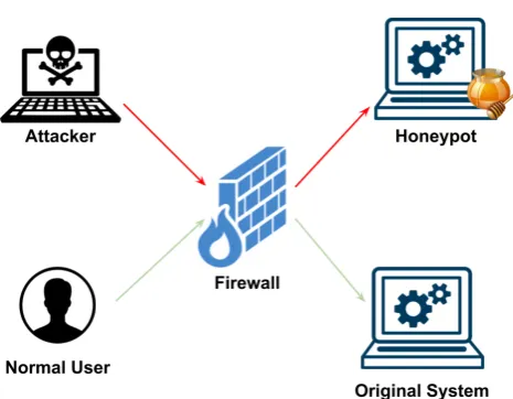
An abstract and simplified model of how a honeypot is integrated in a production system and what is the main purpose of it is shown on Fig.1.1
1.2.2 Functionalities
The main functionalities that one honeypot can implement are:
Data Control: Contain the attack activity and ensure that the compromised honeypots do not fur-ther harm ofur-ther systems. Out bound control without hackers detecting control activities.
Data Capture: Capture all activity within the honeypot and the information that enters and leaves the Honehoneypotynet, without hackers knowing they are being watched.
Data Collection: Captured data is to be securely forwarded to a centralized data collection point for analysis and archiving.
Figure 1.1: Honeypot Integration
Static web server deployment, making it vulnerable
Dynamic IRC, Chat servers, Hackers forums
1.2.3 Types
Based on the complexity and the design of their structure, honeypots can be divided into four cate-gories:
pure honeypots Pure honeypots are fully functional production systems. The activities of the at-tacker are monitored and transmitted over the network. They do not require additional software to be installed. Hence, the level of control over them is limited and not suitable in many sce-narios.
high-interaction honeypots High-interaction honeypots imitate the activities of a production sys-tems. Usually they mimic variety of services and, therefore, an attacker may waste a lot of their time. It is possible to host multiple honeypots on one physical machine. Therefore, when a honeypot is breached, it can be quickly restored. In general, high-interaction honeypots provide more security by being difficult to detect, but they are expensive to maintain.
low-interaction honeypots Low-interaction honeypots simulate only the services frequently re-quested by attackers. They have a short response time, and less code is required. That limited complexity reduces level of security.
medium-interaction honeypots As Georg Wicherski describes in his paper about Medium-Interaction Honeypots[5], they try to combine the benefits of low and high-interaction approaches while re-moving their shortcomings. The key feature of Medium-interaction honeypots is application layer virtualization. These kind of honeypots do not aim at fully simulating a fully operational system environment, nor do they implement all details of an application protocol. All, that these kind of honeypots do is to provide sufficient responses that known exploits await on certain ports that will trick an attacker in interacting with the honeypot.
the first step is to generate a fingerprinting profile of that device.
Looking at the IOT domain again and assuming we have full access to a given device, it would be easier to create a honeypot for it, compared to some more complicated structures. However, the diversity of functionalities, services and hardware make it impractical to create a honeypot for every device that we want to observe. That is why the approach I decided to focus on in this document is the dynamic generation of an IOT cloned device.
1.3
Contribution of the thesis
Chapter 2
Company Case Study
2.1
Cybertrap
My research and implementation were performed during my internship in Cybertrap. CyberTrap is a cybersecurity company located in Vienna, Austria. The motto of the company is to ”always be ahead of the attacker to learn and improve.” Cybertrap achieves that by analyzing their client’s product, puts specific objects (called lures) on selected interesting places for an attacker and redirects the attacker to a decoy when they reach one of the lures. After that, Cybertrap follows every move of the hacker inside that decoy, by obtaining system and program logs. Cybertrap immediately informs the client when there is a breach on their system. Then they are able to determine any security flows in the system and analyze the most common attack vectors that have been used.
Many different honeypots have been created and used. What Cybertrap offers is not just a hon-eypot, but so called Deception platform. A Deception platform contains honeypots as essential com-ponents but go beyond that: they provide the automatic roll out and decommissioning of decoys and services that run on them. They allow for the automatic rollout of lures to the endpoints, which lead attackers to the decoys. Furthermore, they gather, analyze and visualize the collected data, enabling the forensic investigation of breaches and the support of counter actions.
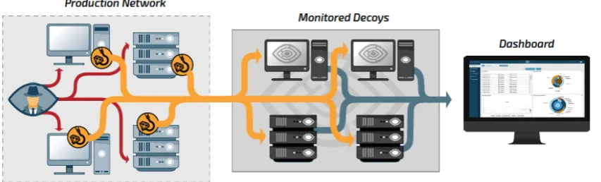
Cybertrap has complex infrastructure, required to provide many valuable features to the cus-tomers. Some of the most important components are variety of possible lures to be installed, software to monitor and response arising attack actions, live dashboard for easy control of the system and much more. All of them are based on the idea that the Decoy will be able to fool the attacker and collect the information of their actions. A simple representation of the Cybertrap platform is shown on Fig.2.1
[image:11.595.98.525.627.756.2]On Fig.2.1 we see that in the Production Network are situated specific lures for every component. When the attacker communicates with any of these components, the lure would be activated and any further interaction would be redirected to the monitored decoys. The main assumption of the decoys is
that they generate similar behaviour which will keep the interest of the attacker and they will believe that they are interacting with the original product. For that purpose all of the monitored decoys need to be adjusted to the original product characteristics. The decoy provide the environment where all of the actions of the attacker are observed, monitored and analyzed in a safe isolated system that would keep all of the malicious attacks away from the company product. The decoys are connected to the dashboard server where they report any action that has been recorded. This data is analyzed and represented in a user-friendly way inside the dashboard website. The user is then able to observe the performed attacks on their system in a systematic way and to respond properly. From the dashboard, the user is able to set, create and modify all the lures and decoys that are integrated in their system in a way to get new and improved insights on the attacks. With all collected information, the user would now know what security problems are available on their system and how they should be mitigated. The desired result is an improved and more secure product that will be in constant state for further change when new attack vectors are registered.
The top features provided from Cybertrap are:
Endpoint deception CyberTrap implements the concept of endpoint deception. Lures that are placed on the endpoints within the production infrastructure direct the attacker to the decoys, where their actions are automatically monitored.
Web application deception CyberTrap can also be used to protect productive web applications. Lures are placed within the web applications that direct attackers to a deceptive web application hosted on a decoy to gather vital threat intelligence.
Tailor-made deception The deception environment appears to be a part of the production envi-ronment. Decoys are configured to look like production machines using deceptive services and data. A varied set of lures is deployed throughout the production network. Since the deception environment is tailor-made for each production environment, it is not finger printable.
Automated deception deployment The web interface allows for the rapid and dynamic creation of new deception campaigns. Services can be configured, filled with data and rolled out to the decoys. Lures can be generated and automatically rolled out to endpoints.
High quality threat intelligence The proprietary monitoring component is invisible to attackers and collects detailed information about every process, thread, file, network
High-confidence alerting Suspicious activity on the decoy triggers an alarm in the web interface, via syslog and email notifications. In addition, the TrackDown service provides alerts when deceptive documents are opened.
Data analysis The Dashboard user interface provides a visual overview of the deception environment enabling a quick overview as well as a detailed forensic analysis down to single system events.
Attacker infrastructure attribution The attribution algorithm of CyberTrap shows the connec-tion between historical IP addresses and their corresponding domain names. An attribuconnec-tion of a command and control server (which is usually used by remote-administration-tool malware) reveals the infrastructure used by the attacker and can also predict from where the next attack could potentially originate.
Integration with security infrastructure CyberTrap integrates with MISP as a proxy for your security ecosystem and feeds SIEMs over syslog.
API All CyberTrap functionality can be accessed via a REST API. This enables the user to integrate the full CyberTrap functionality into existing security solutions.
supported Operating system. This component would be the core of any decoy that will be created. It will be able to save and report the actions that are happening inside that platform. In a second step, this core solution that runs the same Operating System as the original product will be adjusted to the clients software characteristics. This will be done by installing specific programs and modifying important settings.
At the moment CyberTrap offers only Windows-based Decoys. Since the majority of web based applications are using windows servers, it gives Cybertrap the chance to reach and collaborate with the biggest group of potential clients. The goals of Cybertrap are not only to exploit this market share, but to create solutions for new clients that are not using windows as the OS of their products. For that reason, a new Linux-based Decoy is currently being developed. The first prototype of it has been already created and soon it will be distributed to test users and potential clients.
2.2
IOT Decoy
Another expanding area in the modern technologies in the last decade are IOT devices. Cybertrap wants to enter in this field. The goal of the company is to be able to create decoys for different type of IOT devices. In that domain there is no single Operating Systems(if any) adopted from every product. Hence supporting many types of devices would require significant investment in money and time for every one of the devices that should be supported. Therefore, the approach used for the already existing Windows and Linux decoy can not adopted.
The new corresponding approach should take into consideration the differences in the IOT world. For that reason Cybertrap considered that they should change from Operation System level tracking, to application level manipulation. The idea behind that is divided into 2 steps:
• The first is to scan an IOT device and create a fingerprinting profile of it. That profile should include every information that can be obtained and which can be used from an attacker to identify which is the scanned device.
• On the second step, that profile will be used from another software component to generate a honeypot.
The idea of using a profile could not be easily adapted in a way that the full functionality of the device would be included in that profile. Therefore, Cybertrap is interested in creating a Medium interaction honeypot. As I have already explained in the previous section, a Medium interaction hon-eypot works on the application layer and supports only the most important services a given product is running. As a first step, Cybertrap was mostly interested in devices that can be used in the industrial area. Some of the products they were focused on were printers and cameras and the corresponding services they use for printing a document or sending a video stream.
The described approach have many open questions that needed research. Some of them are:
• How such profile should be created?
• What format it should be?
• What information it should contain?
• Which are the services that should be supported and what information about them should be profiled?
• How the profile can be used to generate a medium interaction honeypot without knowing how that service actually works?
Answering to these questions is not trivial task and requires dedicated research that can elaborate if the goal for an IOT decoy is a feasible task and if the idea of generating a profile of that device is the proper way to do it. The research should answer what are the advantages and disadvantages of such approach and should compare them with other projects and solutions that have been focusing on creating honeypot for an IOT device.
2.3
Initial goals
The main focus in the performed research is to identify a scenario how a given unknown IOT device could be profiled. This profile should contain sufficient information so it can be the base of generating a honeypot clone(also referred as a decoy) of that device. The profile should also consists of all the data that can be used to identify that device(a fingerprint).
To cover to maximum extend how an IOT device works, I need to identify an approach and target the most valuable information of it. The full behaviour of any IOT device is considered as a combina-tion of all services it is running. The variety of services that could be supported from a device in the IOT domain is huge and consists of thousands of possibilities. Many of them are custom protocols of the manufacturing company whose software is kept in secret. Due to these circumstances, creating a profiling tool that supports every possible service is extremely difficult task which at that point is considered as not necessary.
During the initial phases of the research and the vision Cybertrap had of the desired future prod-uct, I decided that I should focus on some specific services which are of their primary interest. For every one of them I have to identify which information should be part of the fingerprint and identify a scenario how I can use this fingerprinting information to create a clone copy of that service. After looking in several services I have to develop an approach that will be easy to integrate into other services so they can also be included in the profile. Hence, this approach should be as clear and as general as possible.
Covering only specific services is possible approach that will be sufficient for the initial device profile. Properly selecting these services which are of the main interest for an attacker will keep them busy when that honeypot is generated. As stated before, any custom company service will be very hard to be fingerprinted and supported in our profile. However, this service will also be unknown to the attacker itself. Most of the hackers have difficulties targeting something that they are totally unfamiliar with. I assume that when an attacker starts working on such devices they would try to penetrate the system through the services they are most familiar with and which are prone to security issues.
The performed research and future implementation should be synchronized with the desires, in-frastructure and current products of the host company that would like to adopt the approach and continue its implementation. Many characteristics of the used technologies and the vision of the research should be systematically discussed with a company representative, so a maximum level of awareness and usability are achieved from the results of the performed research.
The process of how new service is analyzed to identify what information should be profiled would be based on the characteristics of that service in general, the complexity of it and the extend that the company want to support it. A valuable insights of how the service works and which are the primary points of interests for an attacker could be obtained by using any penetration testing tool that targets this service. Those tools would then be one of the main components that would be used to determine if the profile and the generated decoy are working correctly and the level of similarity to the original device based on the results of the tool findings.
be concentrated to evaluate if the selected approach is sufficient enough for the goals of the company. I should suggest to what extend that profile could be generalized and how easy it will be to include new services that will be scanned, fingerprinted and simulated.
2.4
Role and Responsibilities
At the beginning of my internship at Cybertrap I was introduced with the current products of the company and with the idea of the IOT decoy project. My role was set to perform an individual research on the questions they needed answers so they can successfully evolve that project. My main focus was on creating a tool that can be used for scanning a given device and generating the finger-printing profile of it. I also had to evaluate my findings by implementing the second part of the project that uses the profile to simulate a virtual device which is running the scanned services. During my internship I have been guided and advised by the project manager of the project - Simon Dimitriadis and with the lead developer for the Decoys implementation - Patrick Pacher. I was also performing regular meetings where I was presenting my progress and findings.
Part II
Chapter 3
Solution Description
In this section I will present the structure of the project I have created to answer the research questions that have been assigned. I will present details of every of the components that are developed and I will explain why they have been designed and implemented in the selected way. Then I will present the results of the analysis of the researched services and based on the findings there I will explain step by step how the approach to integrate them in the profile have been performed.
3.1
Project Structure
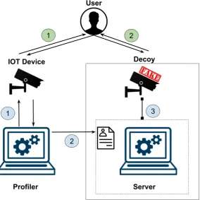
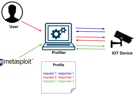
[image:17.595.178.463.433.716.2]There are three main components that are in the essence of the project. (1)A profiler is scanning the device to generate a (2)profile, which is transmitted to a (3)server that reads the profile and runs as a Honeypot(Decoy). This collaboration is presented on Fig. 3.1. Every one of these modules is explained in details in the following subsections. After the decoy is generated, the user is able to communicate with the decoy in the same way as the original device.
3.1.1 Profiler
The first software component is the profiling tool. It is the main focus on my research. The goal of the tool is to extract every valuable information about the targeted device that could determine the behaviour of that device and which would be used from the other main component (the server) to create a honeypot. That honeypot should be as similar as possible as the original device.
While working on the profiler there are several sub-questions that have to be addressed. The first one is to determine which information about an IOT device is necessary to generate such fingerprint. Any output, banner, header, parameter, the order of these elements, the format of an important re-quest, the response itself and so on, could be interesting for us and may be used from the profiler to exfiltrate the fingerprint of the device.
The profiler contains several methods working together that provide the important information for a given scanned service that would be saved in the profile. These methods are:
Information stored inside the profiler Every service that is part of the profiler has been previ-ously researched. Based on the findings from that research I became familiar how that service works, which information is specific for a given device and how it could be obtained as it’s fin-gerprint. Therefore, the profiler knows which requests it should perform so it can receive that information and how it should be extracted. Later on, based on the complexity of the service and the coverage that is supported from the server, I collect either the specific device information, or everything necessary to mimic the service without further knowledge.
Information obtained during the behaviour of the device. During the profiling phase, I give the opportunity to the user to interact with their device in anyway they consider important and which they what to be inserted in the profile. The user is able to request information that is typical for their system. Such information could be: interesting folders, addresses and files that are usually not part of the standard use for that service. For some cases they might enter specific credentials required for accessing the content they would like to be part of the profile.
During this phase, the profiler is collecting every request that has been performed and the responses that the IOT device responds with. Working as a reverse proxy, the profiler is able to store all that valuable information without the need to take care of complication caused by possibly involved encryption.
Information obtained dynamically from a given penetration testing tool(vulnerability scanner)
The third possible way used to collect information from an IOT device is to use third party soft-ware(tool). The expanding attack vectors for a given service makes it very difficult to include these requests in the profile. I assume that in most of the cases the user would not be even familiar if their device is vulnerable to specific attacks. By using external tools I expand the coverage of potential malicious requests that could be performed and which now will be saved in the profile. There are two ways any external tool can be incorporated inside the profiler.
1. The first one is by starting the tool from the profiler itself. This implies that there are a limited number of tools that are specifically selected. Their results have been analyzed and they have been chosen as the best way to represent attacks for the scanned service. Executing these tools can be done automatically from the profiler which guarantees that it is familiar when the the tools execution is completed and can even analyze the final output. Every tool however is another dependency for the project and it needs to be installed on the host machine or bundled inside the profiler project.
The disadvantage of this method is that the tool should be manually started from the user, which breaks the automation execution I have focused on and it also assumes that the user is aware how this should be executed. Hence, this method could be used as an additional feature provided to advanced users who want to extend or customize their profile.
3.1.2 The Profile
The profile is the end result of the scanning(fingerprinting) phase performed from the profiling tool. It contains all valuable information that is necessary to generate the decoy. The profile could even include additional data that the server is not using at a given moment, but could be used in future.
Format
Currently, the profile is a file with JSON format that is easily transferred between the two main components in the Project(from the profiler to the server). During my research, several formats were considered as potential way to store the fingerprinting data. The most promising of them have been analyzed and based on the initial priorities of the research JSON was selected. The list of considered formats that have been considered contains:
• XML
• protobuf
• JSON
The reason why JSON is selected is because it has human readable format which will be useful for debugging purposes. Another advantage of using JSON and in particular as a combination with Python projects, is that the conversion from a class object to a JSON file and the other way around is automatically handled by the system. This way the need to create and update a schema of the profile format is removed(such schema is required in the protobuf format). Hence, I can focus on other more relevant tasks of the research about profiling and decoy creation. However, there are other aspects which may be of big importance for the future of the project, which may require using another format of the profile. Such aspects could be the size of the profile(a protobuf file will have significantly smaller size) and the security of the information inside(in protobuf, the data is not human readable and the schema is required before it can be parsed)
Profile data
The information that the profile contains depends on the services that are found during the scanning of the device. Based on the results from the profiling, the complexity of a given service and the importance of that service, I can structure the results in the following groups:
Service independent information. Some fingerprinting information is not part of the analyzed services. They can represent hardware component data or information that is part of a lower level protocol of the Internet protocol suite[6], and hence that is used from every application level service that I am focusing on. Examples of service independent data are the fields contained in the TCP and IP level protocols. The information of these fields can be used from an attacker to identify the OS of the targeted device. Hence, this data is valuable for the fingerprint and should be stored in the profile. It can be used from the server to adjust the communication parameters used in every application level service that is being simulated.
the existence of open socket on a given port can be used to determine the device type. However, further scanning on that port would easily reveal that it is not a properly functioning service.
In a future step of the project I plan to include additional abstract level of scanning of every service that is not being further supported. This could help us identify if that service can be simulated with some of the automated approaches. However, with zero knowledge of the way that service works, it is a very complicated task that requires further research.
Automated services. For some services the typical behaviour could be easily extracted during the scanning phase. They are of our primary interest and the majority of the approaches explained later in this document are tackling these type of services. For them, there are limited number of requests which determine the base functionality of how that service works. For the goals of a medium interaction honeypot, some of the supported services are simplified by covering only specific service versions or the most used requests that an attacker would be interested in. There are several methods I use to store the service data in such way that it can be repeated after that from the server without much knowledge on the analyzed service. These methods are explained in the next subsection.
Fingerprinted services. Some services are more complex than the others and it is almost impos-sible that they can be fully simulated without the server to have extended knowledge of how that service works. For these services, the normal communication with the device dependants on many factors. For example exchanged settings in previous request would drastically modify any further communication. Other services do not have straightforward pattern of request and responses that can be simulated easily.
For such services, the generated profile contains specifically selected data that can identify the version of the service and some specific characteristics of it. This information can consist of request headers, banners, versions, dependencies and so on. They have been selected by careful analysis of the service specifications and behaviour. This data is then used from the server, to adjust a fully functional service running on the decoy. Such fully service coverage can only be achieved when a specific software that creates a server of the given service and is installed on the decoy. The data of the profile would just be used to make the proper adjustment on the software so it looks as similar as possible to the original device.
3.1.3 The Server
In the process of my current research, the server is a software component that is capable of reading the extracted profile and it creates the matching honeypot. The most important function of the server at this phase of the performed research project is to validate the results obtained during the scanning phase and help us identify the proper way a decoy should be created. The server can give valuable insights of what is actually useful to create a new virtual copy of any device from scratch. The server gives clear view of how the communication with the profiler should be updated in order to solve every limitation or an obstacle that is found in the process of decoy creation. However, the server is not designed to be fully functional honeypot that is ready to be used product. The implementation of such requires proper virtual machine that it will be working on, logging the events that occur, informing a back-end server for these events and much more. All these features are part of a future step in the whole IOT Decoy project. They would be implemented when there are significant insights of which information is important and how it could be used.
or using the same third party tools and compare the responses. This comparison will give us clear observation to what extend the decoy is successfully mimicking the IOT device. If the results are not convincing enough, the user can create more advanced version of the profile by including more requests inside of it. It can be done by using more tools during the profiling phase which will increase the requests coverage from the decoy. Having more request would increase the possibility to respond properly to other attack vectors and would make the similarity between the decoy and the device bigger. This is possible due to the integrated approach of dynamically increasing the number of cov-ered requests and the extendibility of the profile format that can save all desired data in a compact way.
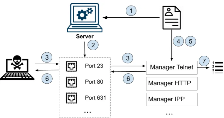
In order to create the decoy from the profile, there are several steps that the server is performing:
1. The server reads the profile and creates a profile object from it.
2. For all the ports that are available in the Profile, the server opens a server socket, where it is listening for incoming connections.
3. When a new connection appears, the server is transferring further analysis of the request to a Manager class that is selected based on the port number which have been reached. Hence, for every supported service the server contains a Manager class that will analyze that specific service data is needed.
4. The manager that receives the request analyzes the data from the incoming request and then selects which data it should return back(if any).
5. If there is at least one data packet that should be returned, the Manager could perform different procedures to update the content of that response, based on parameters that are stored in the profile for that service(or for that concrete response).
6. The updated data packets are send back to the socket where the request was received.
7. For some of the services it is important to keep track for every new request that have been received. For them, the Manager that handles this request, is updating the status of that service.
[image:21.595.120.502.513.715.2]These steps are illustrated in Fig. 3.2
Figure 3.2: Steps for Decoy implementation
a general approach that is service independent on the server suggests having only one general Manager that takes care of the profile analysis. Only services which are simulated with individually installed server software should be separated. That goal is hardly possible at this initial phase of the research due to the different way the analyzed services work. After significant insights are received from how a service should be simulated, then a more general approach can be incorporated. For that purpose all scenarios to save service data explained in the next section, are not strictly service dependant but are designed with generalization perspective.
3.2
Scenarios for storing service data
3.2.1 Request-response scenario
[image:22.595.175.446.325.514.2]This approach is used where there is no significant correlation between the currently performed and the following requests. For them I assume that the response is not dependant on some previous or future communication. This approach is used to simulate the behaviour of IPP and HTTP services. On Fig.3.3 We can see how this approach uses different ways to obtain valuable requests and how they are stored in the profile together with the received response.
Figure 3.3: Request-Response based approach
In order to guarantee maximum correctness of the responses I have integrated several components that build the request-response approach. The first two components are, as the name suggests, the performed request and the received response.
Another module is providing the ability to inform the server about the necessary differences be-tween the raw data stored in the profile and an actual valid response that should be returned. Some examples that illustrate the necessity of such component are fields like:
date. The date when the request has been performed needs to be updated with the date that the incoming request is registered to the decoy.
ip address. In some situations the IP address of the IOT device is send inside the raw data. This address should be updated with the IP address of the Decoy.
request ids Some services, like IPP, has changing field for every received request that is assigned to it. The field should be updated with the new value coming in the request send to the decoy.
To guarantee this process, I save in the profile every difference that should be updated for a given request. By using multiple fields like contained data, regular expressions, exact location and more, I inform the server which part of the raw data should be modified. After the server finds the location of that data, it replaces it with the correct data also provided in the profile if possible(some differences like the date of the new request can not be known in advance and the server should be familiar how to proceed with them).
3.2.2 Specific sequence of requests and responses
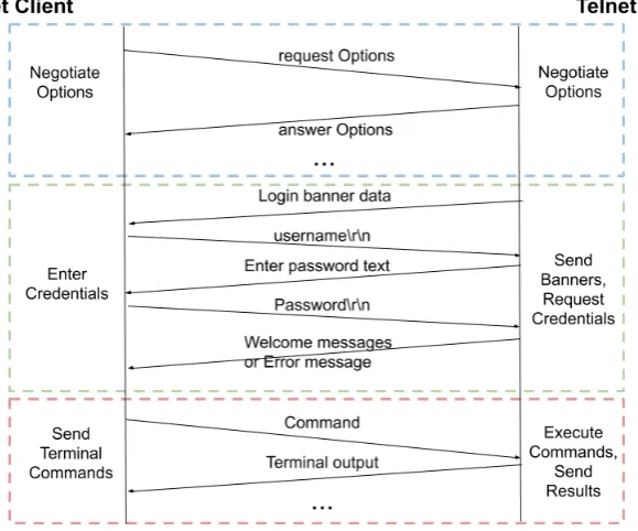
The second approach combines the results of several following requests that are generating specific output. These order of the request is important and can determine which response should be returned from the server.
For most of the services which can not be supported with the request-response approach, it is because there are more than one response for every performed request. It is also possible that there are no responses at all. For these type of services usually there is initial phase(like handshake or negotiation communication) that first need to be performed from the two parties, before they reach the moment where they are exchanging the actual data that is the goal of that service emulation. Therefore, the order that these requests are coming is of significant importance when the server tries to profile that behaviour.
In the next section I will describe which services have been analyzed and integrated inside the project. During their research I have observed how this type of services work and realized that the order of received responses could vary. The main reason of this behaviour is caused of some concur-rency between the operations inside the protocol. Unfortunately it affects the correct results when given response is matched to a request and saved in the profile. Hence, in order to avoid this kind of differences, I use an approach where I perform the captured requests with some delay. This eliminates the possibility to match a received response to the wrong request that is being sent.
Based on the service specifications and the level of simulation we plan to involve, the profiler obtains which requests determine the proper service communication. This process could either be done when these requests are stored in the profiler, or they can be obtained dynamically by analyzing the communication with the original device. The result of the profiling using this method is a list of requests that are following the behaviour of the device that should be cloned, the responses that are transferred for each of them and a way to determine if the responses are valid. The validation of every request would help the server to follow the created correct sequence of requests and return the proper responses if the validation is successful, or corresponding error messages when the validation fails.
in the profile and using them to handle any incoming request by responding with the correct and updated responses.
3.3
Analyzed services
3.3.1 Multi-Service data
In the current project I use a service based approach where I want to profile an IOT device behaviour by analyzing how the presented services work. The type of services which are interesting for simulation are those which the hacker can interact with easily. If we look at the Internet Protocol suite model, those are the application level services. They create the last layer of the model and work with the biggest abstraction from the device physical components. However, there are numerous other protocols and frameworks they depend on for their proper functioning. Some of these non application level services also contain information that could identify a specific device and hence they should be part of the device profile.
TCP
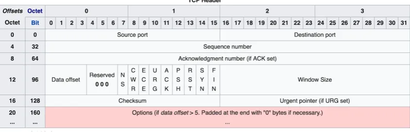
[image:24.595.100.522.395.531.2]Most of the services that are supported in the project are based on the Transmission Control Proto-col(TCP). TCP is a reliably protocol for delivering streams of bytes which represent every file that is being transmitted between two parties[8]. TCP divides every file that should be send into chunks, and adds a TCP header creating a TCP segment. The TCP header has predefined structure including different fields that are required for the proper functioning of the protocol. The structure of a TCP header is presented in Fig.3.4
Figure 3.4: TCP header data
The construction of every TCP header is managed by the operating system through a programming interface that represents the local end-point for communication - the Internet socket. Hence, different operating systems have some differences on the way they instrument the TCP communication. Such changes in most cases are different default values for some of the fields that are part of the TCP header.
IP
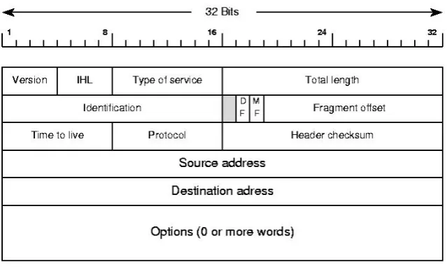
The Internet Protocol (IP) is the main communications protocol in the Internet protocol suite for relaying datagrams across network boundaries. Its routing function enables internetworking, and es-sentially establishes the Internet[9]. IP generates the Internet layer that both TCP and UDP protocols depend on. Similarly to TCP, IP creates an IP header for every packet that is being transmitted. The structure of the IP fragment is shown in Fig.3.5
Figure 3.5: IP header data
[image:25.595.94.529.335.576.2]headers[10]. On Figure.3.6 are shown his results where he identifies which fields in the headers of both protocols are used to identify the operating system of a device.
Figure 3.6: TCP/IP features used to identify an Operation System
3.3.2 IPP What is IPP
The first service that has been researched and implemented is IPP. Cybertrap wished to support printer devices fingerprinting and the popularity of IPP over other printing protocols, gave me the confirmation that IPP is a good candidate for our project.
IPP(Internet Printing Protocol) is a secure application level protocol used for network printing[12]. It defines high-level requests that a client can use to ask the printer for a set of capabilities and settings. The client is also able to send direct commands to the printer and initiate tasks to print a document. IPP is supported by all modern network printers and supersedes all legacy network protocols including port 9100 printing.
IPP defines an abstract model for printing, including operations with common semantic. IPP uses HTTP as its transport protocol. Each IPP request consists of HTTP POST message with a binary IPP data and possibly a file send for printing. The corresponding IPP response is also structured as a POST response. The IPP protocol supports different levels of security. The connections can be unencrypted, TLS encrypted based on HTTP OPTIONS fields, or encrypted immediately with HTTPS.
To communicate with a printer using IPP, the client should use that printer address, also referred as Universal Resource Identifiers (”URIs”). There are two schemes that IPP supports: ”ipp” or ”ipps”, where the second one is using encryption. This URI is used by the client to send the desired operation following the protocol scheme encoding.
Integration in the Project
Integrating IPP in the project requires two steps. The first one is to properly adjust the profiler to make correct IPP requests, and the second step is to implement how the server should read the IPP data from the profile and responds with the right messages.
By analyzing the IPP protocol and the fact that it is running on top of the HTTP, I decided that the most appropriate way to simulate it is by using the request-response approach explained before. The two main reasons for this choice are the fact that every performed request results in exactly one response, and that every request is independent from the others(no sequence needed). Hence, it will give us the possibility to simulate IPP without the need to support fully functional IPP Server running on the decoy.
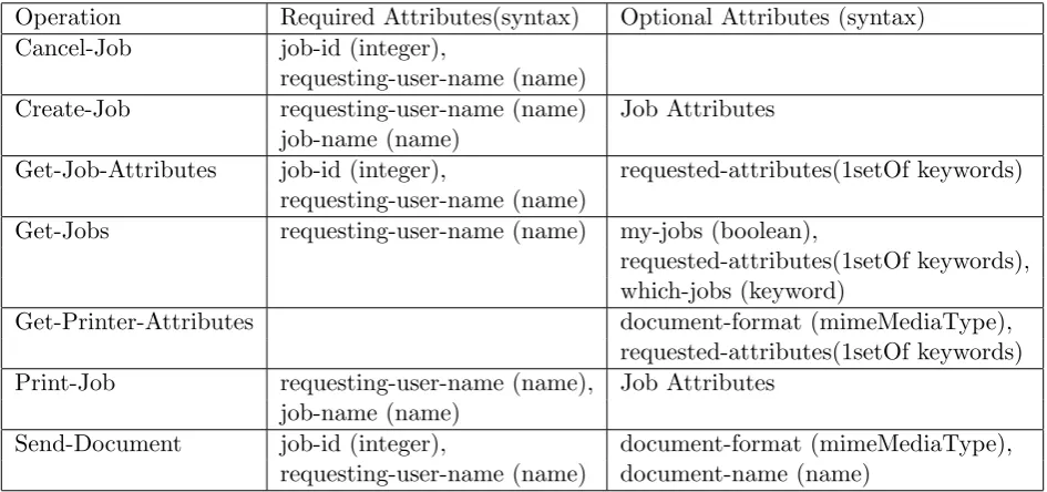
The IPP protocol have in total 16 Job operations[12] that can be used to support any task send by the user. It is also possible that the manufacturer of the device can introduce other custom operations that will be supported from that printer. On Table 3.1, are shown the most common IPP operations.
The limited number of possible operations that can be performed in interaction with the printer remove the uncertainty of which requests should be investigated during scanning. Covering these requests would ensure sufficient level of interaction that would satisfy a medium interaction honey-pot. From the 16 operations that are described in the protocol specifications, I selected the 10 most used by analyzing the communication of the printers with different client applications and tools. I have prepared the IPP Manager inside the profiler to perform these requests as a valid IPP client, by inserting all required fields and attributes. The list of supported operations could be easily extended in the future if that is considered necessary.
Table 3.1: List of most common IPP operations and their attributes
Operation Required Attributes(syntax) Optional Attributes (syntax)
Cancel-Job job-id (integer),
requesting-user-name (name)
Create-Job requesting-user-name (name) Job Attributes job-name (name)
Get-Job-Attributes job-id (integer), requested-attributes(1setOf keywords) requesting-user-name (name)
Get-Jobs requesting-user-name (name) my-jobs (boolean),
requested-attributes(1setOf keywords), which-jobs (keyword)
Get-Printer-Attributes document-format (mimeMediaType),
requested-attributes(1setOf keywords) Print-Job requesting-user-name (name), Job Attributes
job-name (name)
Send-Document job-id (integer), document-format (mimeMediaType),
requesting-user-name (name) document-name (name)
project. The library eases the process to adjust the packets in the required IPP encoding format.
By having all important requests available, the profiler connects to the scanned device uri and per-forms them. The responses received from the printer contain all valuable information that identifies that device and that I need to simulate.
When all responses are received, the data is stored in the profile following the format of the request-response approach. Before being saved, the data is analyzed and all parameters that need to be updated from the server are specified with a list of differences. Then, the ready profile is transmit-ted to the server which is now able to read it’s content and simulate IPP inside the decoy.
Server The purpose of the server is to validate if the selected approach is working properly, with minimum analysis of the requests and responses that are specific for the given service. The IPP Manager follows this idea and automates the profile parsing and returning of the correct response. However, the server needs to properly match the incoming request with one that is saved in the profile. It performs two tasks to correctly achieve it:
identify important parameters from the request Important aspect about the IPP protocol is that it uses custom encoding for the transmitted messages. Each IPP message starts with a version number (2.0 is the most common), an operation id (IPP request) or status code(IPP response), a request number, and a list of attributes.
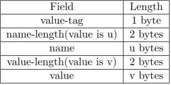
On Table3.2 is presented the format of an IPP message for every available attribute. We see that the length of the message is not fixed in size, but is dependant on the value of the data that is being transmitted.
The server needs to parse the important data of the incoming request. It reads any parameter, attribute and their values following the explained IPP format encoding. All this data is required when the server searches if the new request is presented in the profile.
Table 3.2: Single Value Attribute Encoding in the IPP messages
Field Length
value-tag 1 byte
name-length(value is u) 2 bytes
name u bytes
value-length(value is v) 2 bytes
value v bytes
response, which will be returned in such situations. The most logical and easy to implement approach is to capture an error message and save it together with the remaining 10 operations. However, IPP supports several different error messages based on the type of error that occurs. Supporting different errors will increase significantly the complexity and the analyses that the server should perform. Hence, one error type is selected (client-error-bad-request) which has general looking description and could be a result of different errors. In order to receive that error response in the correct format and fingerprint as the scanned printer, I am performing one more additional request that always results with client-error-bad-request output.
find the appropriate response By comparing the extracted request parameters with the data for every stored request in the profile, the server identifies the response that should be returned.
Another specification of a printer running the IPP protocol is that there might be multiple printer uris for one device. These uris are the addresses at which the communication is happen-ing. The available uris could differ in variety of fields, hence providing different functionalities. For example a printer can have two printer addresses, one of which uses encrypted communi-cation, while the other is unencrypted. Due to the way the selected approach works, having encryption is not problematic for our profiler and the results does change the output inside the profile. I had to integrate some new functionality in the server to make possible having an encrypted communication. One of them is using wrapped sockets with SSL layer, that give us the possibility to support encrypted communication and still be able to read the clear data of the requests and responses.
After the connection is established and the IPP parameters are parsed from the new request, the server is using the operation id of that request and the obtained parameters to identify which is the correct response it has to return. If all of the necessary parameters are valid and they match with a given request from the profile, the server returns it in the sockets after the differences have been updated. If no request from the profile correctly matches the request parameters, the error response is returned.
This approach has several assumptions and limitations. For example, it supports only one default error response, while the protocol supports many other variations. However, it is designed in such way to deliver maximum coverage of the most used IPP features without many of the complications that would arise if the aim is to support every scenario. The behaviour of the decoy and the correctness of the profile would later on be evaluated and it will answer the question to what extent that approach functions properly.
3.3.3 HTTP What is IPP
object management system. A feature of HTTP is the typing and negotiation of data representation, which allows systems to be built independently from the data being transferred.
HTTP is used from variety of protocols which inherits all of the HTTP streaming and security feature. An example of such protocols is the already discussed IPP.
In that document I refer to HTTP as a service. It is actually HTTP server which usually runs on TCP port 80. The HTTP server waits for a client’s request message. Upon receiving the request, the server sends back a status line, such as ”HTTP/1.1 200 OK”, and a message of its own. The body of this message is typically the requested resource, an error message or other information. Often these resources present information which can be observed from user who access them from a web browser. The combination of accessible resources that run on the HTTP server are referred as a Website.
Many IOT devices also have implemented a HTTP server. That website can give information to the user about the current status of the device, or present them with a way to easily control the device. The only required component is a web browser which will be used as the client communicating with the HTTP server. Since Web browsers are implemented for the majority of operation system running on different hardware, that website can be accessed without further requirements.
Analysing HTTP content
Except the transmitted resource, an HTTP response contains several headers used for a proper com-munication with the client. Next is showed an example HTTP response containing several headers.
HTTP/ 1 . 1 200 OK
Date : Mon , 6 May 2019 2 2 : 3 8 : 3 4 GMT Content−Type : t e x t / html ; c h a r s e t=UTF−8 Content−Length : 138
Last−M o d i f i e d : Wed, 07 Jan 2019 2 3 : 1 1 : 5 5 GMT S e r v e r : Apache / 1 . 3 . 3 . 7 ( Unix ) ( Red−Hat / Linux ) ETag : ”3 f 8 0 f−1b6−3e1cb03b ”
Accept−Ranges : b y t e s C o n n e c t i o n : c l o s e
<html> <head>
<t i t l e>An Example Page</ t i t l e> </head>
<body>
<p>H e l l o World , t h i s i s a v e r y s i m p l e HTML document .</p> </body>
</html>
If we take a look at the headers we can easily identify information about the device running the HTTP server and the system it is using. In the presented example there is a server header field that contains the type and version of the HTTP server that has been used.
Almost all HTTP servers differ in the way they implement the HTTP protocol. When the HTTP request is legitimate, the response returned by all HTTP servers is more or less valid with the spec-ifications described in the RFCs for HTTP. However, when the client performs malformed HTTP requests, these servers differ in their responses. Differences in the way HTTP protocol is handled by various HTTP servers constructs HTTP fingerprinting technique.
Table 3.3: Results of HTTP fingerprinting techniques
Server Field Ordering DELETE Method Improper HTTP Improper protocol version
Apache/1.3.23 Date,Server 405 400 200
Microsoft-IIS/5.0 Server,Date 403 200 400
Netscape-Enterprise/4.1 Server,Date 401 505 no header
HTTP header field ordering. Usually the order of the HTTP headers is not important for the proper handling of an incoming request. However, such inconsistency caused by the different HTTP servers, can be used to identify what server is being accessed even without observing the server header.
HTTP DELETE (forbidden operation) response HTTP/1.1 declares 8 possible request method types. They are: GET, HEAD, POST, OPTIONS, PUT, DELETE, TRACE and CONNECT. However, not all of them are allowed from every server. Most of the HTTP servers allow the usage of only several method types. An attempt to make a request with method that is not al-lowed can result in different responses from every type of HTTP server. For example, a DELETE request method can receive response as Method Not Allowed(405), Forbidden(403) or Unautho-rized(401). By observing the response to such attempt, an attacker is able to recognize the type of HTTP server by knowing how it is responding to that specific request method.
Improper HTTP version response Usually the first 8 bytes of an HTTP request contain the version of HTTP that will be used. Constructing HTTP request with non existing version of the HTTP protocol could also lead to variety of different responses from the different HTTP servers. In his example, Saumil Shah is starting the request with HTTP/3.0. As a response he receives messages with codes: Bad Request(400), HTTP Version Not Supported(505) or even OK(200). Knowing how a given type of server responds to such request would reveal itself, even when the server header is not presented.
Improper protocol response Another possibility to craft a non standard request in order to an-alyze the output is just by sending a non proper request. For example this could be achieved by replacing the HTTP version, the type of the request or the uri destination at the beginning of the HTTP request. Some of the tested servers are capable to handle such request, while others respond with Bad Request(400) or even they could not return HTTP response header, but instead just returns an HTML formatted error message stating that this request is a not correct.
A summary of the results and the tested HTTP servers could be seen at Table. 3.3. The version of the tested servers are very old, but the principal that every server could return different responses to a non typical requests is still valid approach for determining the HTTP server type.
All fingerprinting methods described in the previous section are important aspect I want to cover in our profile. However, the observed requests are just a small part of all possibilities of strange requests that a HTTP server could receive. That is why just storing the responses to these specific requests would not be an optimal solution for our fingerprinting tool. A way better approach would be to analyze different tools to determine what requests they are performing, so I would be able to take into account all possible attack vectors that are being addressed.
does not work properly and would eventually conclude that it is not the actual device.
One important characteristics of how HTTP works is that the server always responds to a received request. The number of send requests and the number of received responses should always be the same and the correlation between the requests and responses is 1 to 1. The inconsistency of some other protocols, where there could be multiple requests without received response, or multiple responses to a given request, is not observed in typical HTTP communication. Hence, if I know all headers, parameters, and data that is contained in a given request, the response should always be the same. Here I should mention that when the server is using a backend with a database, the responses could change, but the performed commands are still not altered.
I will use this HTTP characteristics to create our profile. Capturing all important requests and the responses that the server returns would successfully mimic the behaviour of any HTTP server and should be indistinguishable from the original source.
I have already introduced the request-response scenario. Similarly to IPP, it is the approach I used to fingerprint a HTTP server. I will capture the responses to all significant requests and store them in the profile. The work of the server now includes just finding when an incoming request matches to a request that has been stored, and return the corresponding response. This simple interaction eliminated the need for the server to know how HTTP works, by implementing such HTTP server.
During the process of analyzing the request-response tuple I faced two important questions that I need to answer so I can make the whole communication between the profiler and the server more general and corresponding to reality:
Determining when a given request is matched as existing in the profile. A HTTP requests could contain different parameters and headers. Some of them are with significant importance for the HTTP server to manage and return a proper response. Others do not have such value. For example it could be the timestamp of the date when the request was performed. This field should be ignored by our Decoy server when it validates the collected requests, because it will never receive a request with the same timestamp. However, the collected response data would probably still be valid. Determining which parameters are crucial to match a HTTP request could not be done without previous analysis of the results. Unlike IPP where we have limited number of request to cover, potential scanning of an HTTP server could result in thousands of request and they will be different for every device. This lack of standardization makes impossible to analyze the important parameters in advance. Hence, this decision is delegated to the server, which will make customizing the results easier. In the profiler, I just have to ensure that all the parameters are presented so the server could determine which information is critical for the validity of a request, and which could be ignored.
Updating the response data before returning it. Some of the parameters that are being send in a given request are required to establish a proper connection between the two parties. For example the client can put in the request it’s IP address. When the raw response is directly copied inside the profile,these parameters remain untouched. After that the server would use this raw data as a response when the same request is received. However, the server IP address would not be the same as the one that is stored. Hence, the data inside the response would not be valid and the attacker would easily spot such inconsistencies. It is even possible that the connection would not be established at all, or the it will be dropped when the wrong parameter is being processed.
Integration in the Project
The request-response approach that I am using strongly depends on the fact that I can identify which requests are important for the scanned HTTP server. I should also cover significant amount of requests, which are usually used from many vulnerability scanners or just some malicious request send from an attacker. That is why identifying the requests to cover has become of a major importance for the completeness of the profile for HTTP and for the proper functioning of the generated decoy that will use that profile.
All three methods to identify valuable request are used when HTTP is scanned. They have been integrated in the following way:
Information Stored inside the Profiler Figuring out which files are mostly used for HTTP is more difficult than protocols like IPP, where the protocol itself declares the possible commands that the server should support. There are techniques that are used to copy the content of a Web-site. One such technique is Web scraping[15]. It usually implements a bot or web crawler that searches for specific data which is gathered and copied from the web. That approach generates a file content which then can be copied inside a HTTP server which will act as the original server.
The method that is being used is similar to Web scraping, however it collects not the files themselves, but just the requests which are needed for the proper loading of the only page that all servers supports - the index page. The profiler triggers automatic loading of the index page inside a browser(from the profiler it is achieved using the selenium web-driver). Meanwhile, it sniffs the generated traffic. Then it distinguishes all necessary requests called when that index page is loaded. Next, all captured requests are performed again directly from the profiler and the responses are matched and stored. This additional step avoids possible problems with handshakes or encryption that can be used from HTTPS.
Information obtained by following the behaviour of the device. The profiler initiates a phase where a Reverse Proxy is created between the IOT device and the used machine running the profiler. At that moment any interaction with the HTTP server is observed. The user can load any specific page they think should be included in the profile that contains important informa-tion for the fingerprint of the device, or is with significant value for the normal usage of the device.
Information obtained dynamically from a given penetration testing tool(vulnerability scanner)
Many users would not like to communicate with the device during profiling, or they will not be familiar which requests are interesting for an attacker. That is why executing one or more tools which are interacting with the HTTP server is also integrated inside the profiler.
The use of a reverse proxy give us the possibility to not be bound to just specific tools that are integrated inside the project. Every tool that makes requests to the HTTP port could be used to identify potentially interesting requests. Such tools could either be started from the user when the profiling is activated, or they can be triggered from the project. For demonstrative purposes and for easier adaptation from unfamiliar users, the current version of the profiler uses two well known tools for HTTP service scanning(nmap script and Nikto). The results from the performance of the profiler and the usability of the generated profile will be presented in the evaluation chapter.
Comparison to HTTPS