Design Optimization of Heat Transfer in Microchip
Cooling System
Venkata Ramana Murthy Gandi1, Vurity Sridhar Patnaik2, Ravindra Kante3, Uppada Ramakanth4
1
M.Tech Student, 2, 3, 4Department of Mechanical Engineering, #JNTU, Kakinada
Abstract: Thermal Analysis on microchip cooling system with different heat sources like copper and silica, and different varying cross sections of fins are used in this thesis. The main objective of this work is to analyse the heat transfer rate performance of the thermal system i.e. to reduce the maximum temperature and increasing the heat flux of the thermal system with the use of different cross sections of fins without increasing the number of fins. A thermal analysis was performed on microchip cooling system used in computer processors to reduce the Maximus temperature and to increase the heat flux using finite element analysis software. In this study investigation is carried to determine the max temperature and heat flux of the thermal microchip cooling system having rectangular fins and copper source heat generation element. The maximum temperature of the thermal
cooling system is 414.7150K for the rectangular fins and copper heat source in microprocessor cooling system.
The heat flux value maximum for the Octagon type cross section fin and low for the rectangular type cross section fin whereas the triangular type cross section fin gives the better maximum temperature compare to the other cross sections of fins used in the copper source heat generation element in the cooling system.
The triangular cross section fin is good for compare to other cross sections of fins, the max temperature of triangular type fin is
396.2520K, the circular and octagon cross sections fins behaviour is similar in nature in the silicon heat source thermal system.
The heat flux is maximum for the octagon type fin compare to others it was gives the good results, the heat flux value is 0.102726, the other fins behaviour very similar in nature in the silicon heat source thermal system.
Keywords: Maximum Temperature, heat flux, fins, cooling system, ANSYS
I. INTRODUCTION TO FINS
The study heat transfer fins - extend the surface, which is the object, in order to increase the heat transfer rate of the developer or to enhance the convection. The number of conduction, convection, or the object, which determines and transmits to the rays of heat. The increasing temperature gradient between the object and the environment, issues convection heat transfer coefficient and the heat transfer surface is increased and the increase in area. Sometimes fin cannot change its cost-effective to the first two options.
To create a tractable equation for the heat transfer of a fin, many assumptions need to be made:
A. Steady state
B. The constant material properties (independent of temperature)
C. No internal heat
D. One-dimensional conductivity
E. The area of uniform cross-section
F. Uniform surface area for convection
The fins s are the most frequently used heat exchangers, and vehicles such as radiators, the computer CPU power radiators in the anchorage exchangers, and heat. Even those who are new technologies, such as hydrogen fuel mainstream. He took advantage of the phenomena of nature 38. Rabbits and foxes fins or ears to act, releasing heat flowing through their blood.
II. LITERATURE SURVEY
of electronic processor is proposed and an effort is made to decrease the maximum temperature in processor by employing straight rectangular fins which aid in rapid heat removal to the surroundings for ensuring the optimal working of the processor. U S Ramakanth, Veeranjaneyulu Kodeti, Dr. GVR Seshagiri Rao [4] In this work project, 6065 aluminium alloy structural plate elements are taken what mass uncertainty and rigidity take into account with each free edge condition, important information is observed that only spring plate (SP) and bare mass spring plate (SMBP) The frequency of the five modes is the same. The dynamic behaviour of plates in vibrations was discovered using FEM technique. This shows a good agreement between analyses Methods and finite elements Methods for blank plates under various boundary conditions. U. S. Ramakanth, Putti. Srinivasa Rao [5] presents the research examined the influence of sic and fly ash on the wear behaviour of Aluminium 7075/5 and weight percentage of hybrid
complex. Aluminium alloy 7075 strengthened with sic-fly ash were examined. Uppada Rama Kanth, Putti Srinivasa Rao, Mallarapu
Gopi Krishna [6] reports that Al-Zn compound supplement / fly ash / Thus, using a device to measure the vortex of casting, while
stirring. The carrots are many thermal power plants Industrial waste fly ash, the main service. This article reports on the skill of the Microstructural and mechanical behaviour, zinc aluminum alloy, reinforced with fly ash and silicon carbide (SiC). M. Prashanth Reddy, C. Labesh kumar and T. Vanaja [7] the development of the digital computer and its usage day by day is rapidly increasing. But the reliability of electronic components is getting affected critically by the temperature at which the junction operates. N.Venkatesh, .M. Kedarnath [8] Mechanical housing play critical role in ground electronic devices. It houses Printed Circuit Boards (PCBs) on which high heat dissipating components will be mounted. The complexity associated with this requirement is to dissipate the heat to the ambient through constrained heat path. K a Rajput, A V Kulkarni [9] it is very important to dissipate unwanted heat generated in mechanical devices such as IC engines, radiators, electronic IC’s etc. to the atmosphere. Extended surfaces are widely used in many engineering application because of easy in construction, require less space, light weight. A Sathishkumar, MD KathirKaman, S Ponsankar, C Balasuthagar [10] The major automobile component subject to high temperature variation and thermal stress is engine cylinder. Fins are used on the surface of engine cylinder to increase the heat transfer rate. Heat rejection rate in engine cylinder fins can be enhanced by increasing its surface area.
A. Finite Element Analysis of Microchip Cooling Thermal System
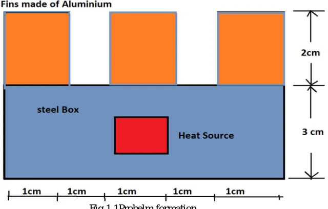
The heat source material used in this analysis is copper of thermal conductivity (K 386 W/mºK and fin material used as aluminium with thermal conductivity of 180 W/mºK for cooling the system environment and the entire system is Enclosing in a container is made of a steel with thermal conductivity of 17 W/mºK. Thermal system is keep in steel box. The purpose of attaching the rectangular fins in the thermal systems is reduce the heat generated by the heat source. The convection or film coefficient “h” takes
place on the boundaries of the thermal system, the ambient temperature is 200c is maintained, the bottom surface is insulated and the
[image:2.612.167.487.510.714.2]heat generation rate is 1W as shown in fig 3.1. The thermal conductivity of Steel, Aluminium and copper are taken as 17 W/mºK, 180 W/mºK and 386 W/mºK shown in the table 1.1. The purpose of this study is to reduce the heat in the system for this first to find the maximum temperature after that the analysis is carried out using different cross-sections of the fins.
The results are found using General post processor command in ANSYS. There are two types of results available in ANSYS software (1) plots (2) list. In plots results display with different colours, the red colour indicate the maximum value and the blue colour indicate minimum value. The list command show the values numerically. The maximum temperature of the thermal cooling system is found using the Fig 1.2 is 414.715 for the rectangular fins and copper heat source in microprocessor cooling system.
Fig 1.2Thermal loading acting on the body & the maximum temperature distribution of the thermal system
B. Thermal Analysis on Copper Heat Source Microchip Cooling System under Different Cross Sections of Fins
To reduce the maximum temperature and increasing the heat flux in copper source microchip cooling system different cross sections of the fins are used without adding the number of fins. The following cross sections are used for fins
1) Circular, Triangular,& Square
2) Pentagon, Octagon, & Hexagon
The convection or film coefficient “h” takes place on the boundaries of the thermal system, the ambient temperature is 200c
(20+273=2930K) is maintained, the bottom surface is insulated and the heat generation rate is 1W .The thermal conductivity of
Steel, Aluminium and copper are taken as 17 W/mºK, 180 W/mºK and 386 W/mºK. The purpose of this study is to reduce the heat in the system for this first to find the maximum temperature after that the analysis is carried out using different cross-sections of the fins. The circular fin was created having radius 5.5mm, the circular fin model thermal system the maximum temperature found that
414.335OK and heat flux 0.100476.The triangular fin radius 8.2mm making an angle of side length 291.36, the triangular fin model
thermal system the maximum temperature found that 395.594OK and heat flux 0.102632.The square fin radius 5.5mm making an
angle of side length 263.92, the square fin model thermal system the maximum temperature found that 408.258OK and heat flux
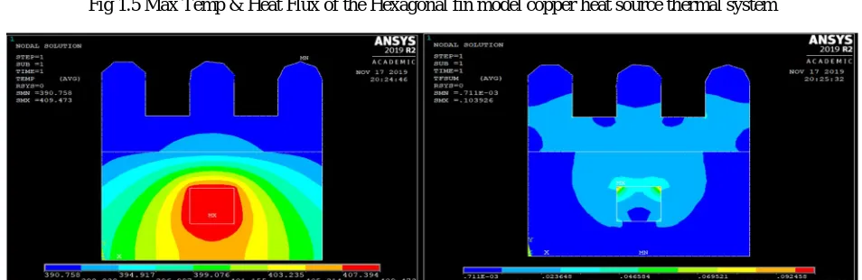
0.102672.The hexagon fin radius 5.5mm making an angle of side length 270 the Hexagon fin model thermal system the maximum
temperature found that 407.578OK and heat flux 0.102646.The pentagon fin model thermal system the maximum temperature found
that 408.128OK and heat flux 0.103733. The octagon fin radius 5.36 mm making an angle of side length 298.82, the octagon fin
model thermal system the maximum temperature found that 409.473OK and heat flux 0.103926.
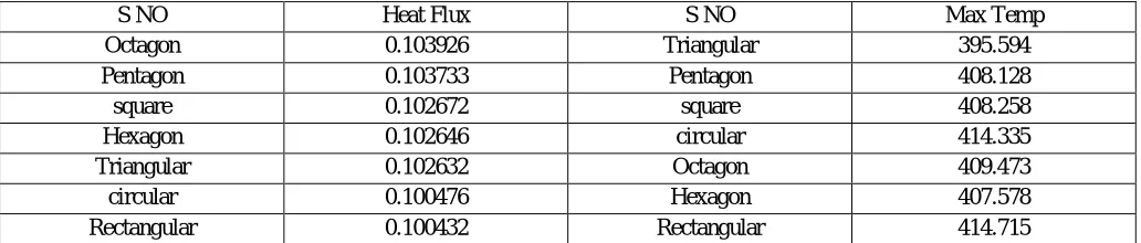
[image:3.612.35.551.622.732.2]The Table 1.1 and Fig 1.3 to Fig 1.6 represents the heat flux values and maximum temperatures of the different cross sections of fins used in the microprocessor thermal cooling system. The heat flux value maximum for the Octagon type cross section fin and low for the rectangular type cross section fin used in the copper source heat generation element in the cooling system. The triangular type cross section fin gives the better maximum temperature compare to the other cross sections of fins used in the copper source heat generation element in the cooling system.
Table 1.1 shows the heat flux values and Max Temp of different cross sections of fins
S NO Heat Flux S NO Max Temp
Octagon 0.103926 Triangular 395.594
Pentagon 0.103733 Pentagon 408.128
square 0.102672 square 408.258
Hexagon 0.102646 circular 414.335
Triangular 0.102632 Octagon 409.473
circular 0.100476 Hexagon 407.578
Fig 1.3 Max Temp & Heat Flux of the circular fin model copper heat source thermal system
Fig 1.4 Max Temp & Heat Flux of the triangular fin model copper heat source thermal system
Fig 1.5 Max Temp & Heat Flux of the Hexagonal fin model copper heat source thermal system
[image:4.612.67.544.564.719.2]C. Thermal Analysis on Silicon Heat Source Microchip Cooling System under Different Cross Sections of Fins
The convection or film coefficient “h” takes place on the boundaries of the thermal system, the ambient temperature is 200c
(20+273=2930K) is maintained, the bottom surface is insulated and the heat generation rate is 1W .The thermal conductivity of
Steel, Aluminium and silicon are taken as 17 W/mºK, 180 W/mºK and 130 W/mºK. The purpose of this study is to reduce the heat in the system for this first to find the maximum temperature after that the analysis is carried out using different cross-sections of the fins. Fig 1.7 & Fig 1.8 show the Max temp and Heat flux of Triangular, Pentagon & Octagonal l fin model silicon heat source thermal system
To reduce the maximum temperature and increasing the heat flux in silicon source microchip cooling system different cross sections of the fins are used without adding the number of fins. The circular fin was created having radius 5.5mm, the circular fin
model thermal system the maximum temperature found that 407.011OK and heat flux 0.085091.The triangular fin radius 8.57mm
making an angle of side length 272.61, the triangular fin model thermal system the maximum temperature found that 396.252OK and
heat flux 0.08516.
The square fin radius 5.15mm making an angle of side length 267.77, the square fin model thermal system the maximum
temperature found that 409.677OK and heat flux 0.08411.The hexagon fin radius 5.1mm making an angle of side length 297.43, the
hexagon fin model thermal system the maximum temperature found that 408.676OK and heat flux 0.08455.
The pentagon fin model radius 5.82mm making an angle of side length 306.16 thermal system the maximum temperature found that
404.64OK and heat flux 0.084882. The octagon fin radius 4.9 mm making an angle of side length 272.78, the octagon fin model
thermal system the maximum temperature found that 407.311OK and heat flux 0.102726.
Fig 1.7 Max Temp of the Triangular, Pentagon & Octagonal l fin model silicon heat source thermal system
Fig 1.8 Heat Flux of the Triangular, Pentagon & Octagonal l fin model silicon heat source thermal system
D. Results and Discussions
1) Results of Various Cross Sections Of Fins With Copper Heat Source: The maximum temperature of the thermal cooling system
is 414.715oK for the rectangular fins and copper heat source in microprocessor cooling system. The circular fin model thermal
system the maximum temperature found that 414.335OK and heat flux 0.100476. The triangular fin model thermal system the
maximum temperature found that 395.594OK and heat flux 0.102632. The square fin model thermal system the maximum
temperature found that 408.258OK and heat flux 0.102672. The Hexagon fin model thermal system the maximum temperature
found that 407.578OK and heat flux 0.102646. The Pentagon fin model thermal system the maximum temperature found that
408.128OK and heat flux 0.103733. The octagon fin model thermal system the maximum temperature found that 409.473OK
and heat flux 0.103926. The Fig 1.9 shows the heat flux value maximum for the Octagon type cross section fin and low for the rectangular type cross section fin used in the copper source heat generation element in the cooling system. The triangular type cross section fin gives the better maximum temperature compare to the other cross sections of fins used in the copper source heat generation element in the cooling system.
2) Results of Various Cross Sections Of Fins With Silicon Heat Source: Fig 1.10 shows the Max Temp and heat flux versus Various Fin Cross Section of Silicon Heat Source. The triangular cross section fin is good for compare to other cross sections of
fins, the max temperature of triangular type fin is 396.2520K, the circular and octagon cross sections fins behaviour is similar in
nature. The heat flux is maximum for the octagon type fin compare to others it was gives the good results, the heat flux value is 0.102726, the other fins behaviour very similar in nature.
Fig 1.9 Max Temp and Heat Flux Versus Various Cross Section of fin with copper heat source
Fig 1.10 Max Temp and Heat Flux Versus Various Cross Section of fin with silicon heat source
385 390 395 400 405 410 415 420 M AX T E M P E R AT U R E
Max Temp Versus Various Cross Section of fin 0.098 0.099 0.1 0.101 0.102 0.103 0.104 0.105 H ea t Fl u x
Heat Flux Various Cross Section of fin
385 390 395 400 405 410 415 420 M ax T em p
Max Temp versus Various Fin Cross Section of Silicon Heat Source
0 0.02 0.04 0.06 0.08 0.1 0.12 H ea t fl u x
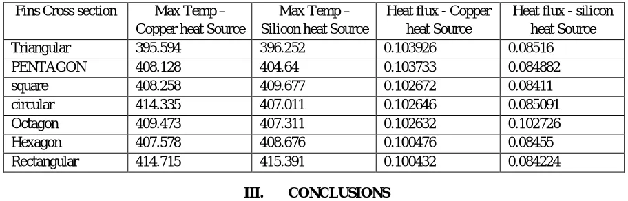
3) Copper and silicon heat source Comparison: Table 1.2 represents the copper, silicon heat source computed data in ANSYS. The triangular fin gives the reduction of temperature compare to other cross section type fins whereas the copper heat source system is better than silicon heat source thermal system. Observed that the rectangular type pin gives the same max temp in copper and silicon heat source. The Heat flux values of all types fins cross section with copper and silicon heat source thermal system. Almost all are gives same heat flux values but in copper heat source the triangular fin gives the good results and in silicon heat source octagon pin gives the better results are observed.
Table 1.2 Copper and silicon heat source Comparison
Fins Cross section Max Temp –
Copper heat Source
Max Temp – Silicon heat Source
Heat flux - Copper heat Source
Heat flux - silicon heat Source
Triangular 395.594 396.252 0.103926 0.08516
PENTAGON 408.128 404.64 0.103733 0.084882
square 408.258 409.677 0.102672 0.08411
circular 414.335 407.011 0.102646 0.085091
Octagon 409.473 407.311 0.102632 0.102726
Hexagon 407.578 408.676 0.100476 0.08455
Rectangular 414.715 415.391 0.100432 0.084224
III. CONCLUSIONS
A. The maximum temperature and heat flux values are determined for different cross sections of fins used in copper and silicon
heat source cooling systems.
B. The analysis was carried with the help of powerful tool finite element analysis software ANSYS successfully.
C. The copper and silicon heat source results are compared and give the best cross section of fin in the thermal system.
IV. FUTURE SCOPE
A. Today the composite materials having good properties, the usage of those materials for fins are gives better results.
B. Also use composite materials for heat source devices
REFERENCES
[1] M. G. Sobamowo, “Finite element analysis of transient thermal performance of a convective-radiative cooling fin: effects of fin tip conditions and magnetic field”, Research on engineering structures & materials (RSEM)”, Article history: Received 25 Jun 2018 Revised 02 Oct 2018 Accepted 25 Oct 2018 [2] H. Singh, J.S. Crompton*and K.C. Koppenhoefer, “Convective Cooling of Electronic Components”COSMOL conference in Bostan in 2013.
[3] M. Bisht, K. S. Mehra, “Optimization of Working of Processor by Fins Using FEM” International Journal for Research In Applied Science And Engineering Technology (I JRAS ET)” Vol. 2 Issue VIII, August 2014 ISSN: 2321-9653
[4] U S Ramakanth, Veeranjaneyulu Kodeti, Dr. GVR Seshagiri Rao” Modal Analysis of Aluminium alloy 6065 Plate with Uncertainty under Various Boundary Conditions” International Journal for Research in Applied Science & Engineering Technology (IJRASET) ISSN: 2321-9653; IC Value: 45.98; SJ Impact Factor: 6.887 Volume 6 Issue II, February 2018- Available at www.ijraset.com
[5] U. S. Ramakanth; Putti. Srinivasa Rao “Wear Behavior of AL 7075/FA/SiC Hybrid Composites”,”International Journal of Mechanical and Production Engineering Research and Development (IJMPERD)”, (Vol.9, No. 2), Scopus Indexed (IJMPERD) with ISSN & Impact Factor (JCC).
[6] Uppada Rama Kanth, Putti Srinivasa Rao, Mallarapu Gopi Krishna, “Mechanical behaviour of fly ash/SiC particles reinforced Al-Zn alloy-based metal matrix composites fabricated by stir casting method”, “he Journal of Materials Research and Technology (JMRT),SCI, Vol 8 pages 737-744 (January - March 2019). [7] M. Prashanth Reddy, C. Labesh kumar and T. Vanaja, “Thermal Modeling and Manufacturing of Heat Sink for Cooling CPU” International Journal of
Mechanical Engineering and Technology (IJMET) Volume 8, Issue 9, September 2017, pp. 502–509, Article ID: IJMET_08_09_054 Print: 0976-6340 and ISSN Online: 0976-6359.
[8] N.Venkatesh, .M. Kedarnath, “Thermal Design and Analysis of Mechanical Housing Using Ansys” Int. Journal of Engineering Research and Application www.ijera.com ISSN: 2248-9622, Vol. 7, Issue 9, (Part -1) September 2017, pp.77-83.
[9] K A Rajput, A V Kulkarni, “Finite Element Analysis of Convective Heat Transfer Augmentation from Rectangular Fin by Circular Perforation” International Journal on Recent Technologies in Mechanical and Electrical Engineering (IJRMEE) ISSN: 2349-7947 Volume: 2 Issue: 5 037 – 042.