Abstract— In this research study, the characterization of the microstructure evolution of friction stir lap welds (FSLW) of Aluminium incorporated with Titanium Carbide powder to form Aluminium based composites is presented. The Titanium Carbide powder was infused at the weld interface to produce a composite. The FSLW were conducted on an Intelligent Stir Welding for Industry and Research (I-STIR) Process Development System (PDS). Different welding parameters were used for the welding process. Rotational speeds of 1600 rpm and 2000 rpm and transverse speeds of 100 mm/min, 200 mm/min and 300 mm/min were employed. The process parameters were carefully selected to represent a low, medium and high setting for the feed rates. The microstructural evolution of the samples were studied. Optical microscope and scanning electron microscopy (SEM) techniques were used to investigate the particle distribution of the welded samples. The results obtained revealed the influence of the welding parameters on the particle distribution of the welded samples. A homogenous mixture of the materials was observed at higher rotational speed of 2000 rpm.
Keywords— aluminium, friction stir welding, microstructure, Titanium Carbide (TiC)
I. INTRODUCTION
oining of Aluminium in lap configuration has a wide range of applications and is very essential in manufacturing and production of automobile, marine and aerospace parts and the making of pipelines in the energy industries. Different welding and joining techniques like metal inert gas (MIG) welding, tungsten inert gas (TIG) welding, riveting, brazing and fastening [1-2] have been employed to produce Aluminium joints in lap configuration but the sensitive nature of the metallurgical properties of Aluminium materials makes
Manuscript received March 20, 2015; revised April 1, 2015. This work was supported and financed by the University of Johannesburg under the GES award scholarship of Postgraduate research centre.
O. O. Abegunde is a Masters Candidate in the Department of Mechanical Engineering Science, University of Johannesburg, Auckland Park Kingsway Campus, Johannesburg, South Africa, 2006. (Phone-+27620320634; E-mail: [email protected]).
E. T. Akinlabi is an Associate Professor and the Head of Department in the Department of Mechanical Engineering Science, University of Johannesburg, Auckland Park Kingsway Campus, Johannesburg, South Africa, 2006. (E-mail: [email protected]).
D. M. Madyira is a Lecturer in the Department of Mechanical Engineering Science, University of Johannesburg, Auckland Park Kingsway Campus, Johannesburg, South Africa, 2006. (E-mail: [email protected]).
it almost impossible to use these welding techniques without the formation of oxide and other contaminants which alter and adversely compromise the properties of Aluminium. Though, joining techniques such as bolting and riveting require no or little heat but are not totally reliable because they facilitate the development of stress concentrations which promote the initiation and propagation of cracks due to the presence of rivet and bolt holes [3].
[image:1.595.323.532.500.646.2]The volatile nature of the metallurgical properties of Aluminium led to the development of solid state technique for joining aluminium and related alloys developed by The Welding Institute (TWI) UK in 1991 referred to as Friction Stir Welding (FSW) [4]. The basic concept of FSW involves a non-consumable rotating tool with specific designed pin and shoulder depending on the type of material and the joint configuration desired in the materials to be joined. The pin and the shoulder constitute the rotating tool which transverses along the seam of the desired joint as shown in Figure 1 [5]. FSW was initially applied to Aluminiun and its alloys but over time, it has been used on other materials and it is also identified to as a cutting edge technology in the field of welding [6].
Fig. 1. Schematic diagram of FSW process [5]
The tool which is made up of the tool pin and shoulder is responsible for heating the workpiece and material movement to produce the desired joint. Different joint configurations like butt joint, lap joint and fillet joint are achievable with the FSW process. The major benefits that distinguished FSW from other welding techniques are no melting of materials, homogenization of precipitate in the production of metal matrix composites, refinement of the microstructure,
Microstructural Characterization of Friction Stir
Lap Welds of Aluminium Incorporated with
Titanium Carbide
Olayinka O. Abegunde, Esther T. Akinlabi and Daniel M. Madyira,
Member, IAENG
densification and excellent homogeneity of weld zone [5-6]. Friction Stir Lap Welding FSWL is a variant of FSW. FSLW is a process of lapping the work pieces, where the surfaces of the top and the bottom plates is stirred and mixed in the stir zone thus forming a weld behind the tool. FSLW is made up of two sides which are the advancing and retreating sides. The advancing side of the weld is the side of the tool where the rotation of the tool and the welding direction are the same while the retreating side is the side of the tool where the rotation of the tool is opposite that of the welding direction. FSW is currently used in a number of applications and has potential for wider applications. [7-8]
In FSLW, defects like wormholes, kissing bond caused by insufficient heat generated and heat transferred during welding, thinning effect on the original joint line faying surface caused by excessive vertical flow (hot weld), which may decrease shear strength and hooking defect seen at the advancing side when the sheet interface is pulled up into the top sheet are major defects in lap welding because the working temperature is below the melting point of Aluminium. However, appropriate choice of the operating processing parameters eliminates defects and thereby result in welds with sound joint integrity [3]. The major process parameters that define the integrity of FSW lap welding are tool rotation, plunge depth and transverse speed. These are responsible for flow of material and heat transfer during the welding process [3, 5, 6]. FSLW is a potential and competitive technique for welding Aluminium. The applications of FSW for lap welding of Aluminium and its alloy have been reported by different researchers [3]. Bisadi et al [3] investigated the influence of process parameters on the microstructure and mechanical properties of friction stir welding of Al 5083 alloy lap joint and reported that with proper choice of process parameters during welding, these defects can be mitigated and eliminated. Yazdanian and Chen [9] also suggested that using a pin length slightly greater than the sheet thickness resulted in a metallurgically sound weld and an increase in the rotational speed may lead to high degree of hooking.
Several techniques have been reported to produce Aluminium matrix composite (AMC). Plasma air spraying, stir casting, squeeze casting, molten metal infiltration and powder metallurgy were reported for producing bulk composites while high energy laser melt injection, plasma spraying, cast sinter and electron beam irradiation have been used for producing surface composites [10-11]. AMCs have already found commercial applications in defence industries, aerospace, automobile and marine due to their favorable metallurgical properties [11].
However, research works [12-14] have been reported on friction stir processing of AMC and Al-TiC surface composites. These studies concluded that the metallurgical properties can be improved and more uniform homogenous particle distribution was observed during double passes. Dhayalan et al. [15] investigated the characterization of AA6063/SiC-Gr surface composites produced by FSP technique and concluded that the grain sizes were refined and homogenous mixture distribution of ceramic particulates was noticed at the stir zone. Puviyarasan and Praveen [16] studied
fabrication and analysis of bulk SiCp reinforced aluminium metal matrix composites using FSP and observed good interface formation between the particles and the base metal. Based on the available literature, previous research works have been limited to surface composite using FSW process and lap welding without addition of reinforcement particle to the weld interface, whereas such strategy provides a novel means in the weld joint. Literature suggests that no attempts have been made to that produce lap welds with Titanium Carbide (TiC) incorporated as reinforcement particles to form aluminium metal matrix composites. The addition of the TiC ceramics particles is due to its favourable mechanical properties[17-18].
In the present work, an Aluminium lap joint reinforced with TiC powder at the weld interface was produced via FSLW and the effect of process parameters on the weld integrity was studied. Furthermore, the microstructure distribution of the lap joint interfaces of the Al-TiC composites formed was equally analyzed.
II. EXPERIMENTAL SETUP
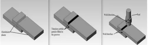
[image:2.595.306.557.627.704.2]Aluminium sheets of 400 mm x 210 mm x 3 mmwere used for this research work. A V-groove of 400 mm x 4 mm x 1 mm was made on both the top and the bottom sheets and Titanium Carbide particles were filled and compacted in the groove as shown in Figure 2. The friction stir welding machine used is Intelligent Stir Welding for Industry and Research (I-STIR) Process Development System (PDS) at the eNtsa of Nelson Mandela Metropolitan University, Port Elizabeth, South Africa. Table I summarizes the welding parameters (rotational speed and transverse speed) and visual observations for six the different samples produced. The tool used is an H13 tool steel hardened to 52 HRC and the chemical composition of the aluminium is presented in Table II. The metallographic samples preparation was done in accordance to ASTM E3-95 [19] for microstructure analysis. The samples were prepared perpendicular to the weld direction. Grinding and polishing were carefully done on the samples to obtain mirror finished samples. Keller's reagent was used for etching for proper observation of the grains. Optical microscope DP25 OLYMPUS and scanning electron microscope TESCAN were used for the microstructural analysis.
TABLE I
WELDING PARAMETERS OF FSLW OF ALUMINIUM AND TITANIUM CARBIDE COMPOSITES
Sample Rotation
al Speed (Rpm)
Transverse Speed (Mm/Min)
Visual Observation
A 1600 100 Presence of wormholes Coarse surface finishing B 1600 200 Presence of wormholes
Coarse surface finishing C 1600 300 No wormhole
Partially coarse surface D 2000 100 No wormhole and meagre
flashes
Smooth surface finishing E 2000 200 No wormhole and meagre
flashes
Smooth surface finishing F 2000 300 No wormhole and meagre
flashes
Smooth surface finishing
TABLE II
CHEMICAL COMPOSITION OF THE ALUMINIUM
% Maximum
Manganese (Mn) 0.05 Iron (Fe) 0.04 Copper (Cu) 0.05 Magnesium (Mg) 0.05 Silicon (Si) 0.25 Zinc (Zn) 0.07 Titanium (Ti) 0.05 Aluminium (Al) Balance
III. RESULTS AND DISCUSSION
The results obtained from this present study are presented and discussed in this section.
A. Visual Observations
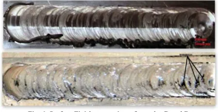
[image:3.595.309.546.188.313.2]FSWL was carried out using the process parameters shown in Table 1. Figure 3 shows the FSLW top zones of the welded samples at rotational speed of 1600 rpm and transverse speeds of 100 mm/min, 200 mm/min and 300 mm/min and FSLW zone at 2000 rpm rotational speed at 100 mm/min, 200 mm/min and 300 mm/min transverse speeds respectively.
Fig. 3. Processed FSLW samples at different welding parameters
It was observed that the surface finish of the samples produced at rotational speed of 2000 rpm is better than that produced at 1600 rpm due to the sufficient heat generated at 2000 rpm. Continuous defect free surface was also observed for all the samples produced at 2000 rpm but wormholes are visible on Sample A and B produced at rotational speed of 1600 rpm as shown in Figure 4 and Figure 5 respectively due to improper stirring and mixing of the materials.
Fig. 4. Sample A with visible wormholes
Fig. 5 Sample B with visible wormhole
[image:3.595.316.541.421.537.2]Another visible observation is the smoothness of the surface finish obtained at higher rotational speed of 2000 rpm compared to the coarse surface observed on the weld produced at 1600 rpm as shown in Figure 6. This can be attributed to the proper movement of materials from the front of the tool to the back to complete the welding process at high rotational speed of 2000 rpm.
Fig. 6. Surface Finish comparism of samples D and B
The presence of wormholes on welds produced at low rotational speed of 1600 rpm is due to insufficient heat around the weld interface. The presence of the TiC at the weld interface reduces the thermal conductivity of Aluminium and insufficient heat is transferred from the top sheet to the bottom sheet, causing inhomogeneous mixture of TiC which resulted in a cold weld. As the rotational speed increases, the heat generated around the weld interface also increases and the heat transfer from the top sheet to the bottom sheet was sufficient enough to yield good weld.
B. Microstructural Evaluation
[image:3.595.68.269.620.724.2]Fig. 7. SEM Photomicrograph of TiC Powder
Figure 8 shows the optical micrograph of welds at rotational speed of 1600 rpm and transverse speed of 100 mm/min. Typical wormhole defects in FSLW were observed in samples A and B at rotational speed of 1600rpm. The stirring and mixing of the TiC powder in the stir zone was not sufficient to produce good weld, thereby displacing the TiC particle infused in the groove and creating vacuum which led to the formation of pores around the weld zone as shown.
[image:4.595.313.545.117.263.2].
Fig. 8. Defect observed at rotational speed of 1600 rpm and transverse speed of 100mm/min
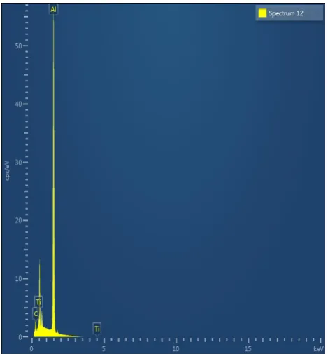
At higher rotational speed of 2000 rpm and transverse speed of 100 mm/min, homogenous distribution of TiC particles was observed as shown in Figure 9a. It is observed that the Al and TiC particle in the stir zone have been refined during the FSW process. The uniformly distributed particle was confirmed to be TiC using EDS analysis shown in Figure 10. The effect of the transverse speed at higher rotational speed was exponential. As the transverse speed increases, the distribution of the particles becomes inhomogeneous due to the fact that the tool moves very fast, hence the tool-material interaction time is low. For sample F, though good visual image of the weld seam was observed but the micrograph revealed under SEM shows some defect in Figure 9c. This implies that the effect of transverse speed is exponential while
that of the rotational speed is linear on the quality of the weld and the refinement of the microstructure.
[image:4.595.311.546.294.547.2]Fig. 9. SEM Micrograph A. Homogenous distribution B. Weld Interface C. Defect observed at high transverse speed
Fig. 10. EDS from the weld interface
IV. CONCLUSION
[image:4.595.62.264.407.554.2]Nomenclatures
% percentage
Acronyms
Al Aluminium TiC Titanium Carbide
EDS Energy dispersive X-ray spectroscopy FSW Friction stir welding
FSLW Friction stir lap welding FSLWed Friction stir lap welded SEM Scanning electron microscope
ACKNOWLEDGEMENT
The authors would like to acknowledge the eNtsa Research Group of Nelson Mandela Metropolitan University (NMMU), Port Elizabeth, South Africa for allowing us to use their facility to produce the welds.
REFERENCES
[1] D. Fersini and A. Pirondi, Fatigue behaviour of Al2024-T3 friction stir welded lap joints, Engineering Fracture Mechanics, Vol. 74, no. 1, pp. 468–480 (2007).
[2] M. Ericsson, L.Z. Jin and R. Sandstrom, Fatigue properties of friction stir overlap welds, International Journal of Fatigue, Vol. 29, no. 1, pp. 57–68 (2007).
[3] H. Bisadi, M. Tour and A. Tavakoli, The influence of process parameters on microstructure and mechanical properties of friction stir welded Al 5083 alloy lap joint, America Journal of Materials Science, Vol. 1, no. 2, pp. 93-97 (2010).
[4] W. M. Thomas, E.D. Nicholas, J.C. Needham , M.G. Murch, P. Templesmith and C.J. Dawes, Improvement Relating To Friction Welding, International Patent Application December (1991).
[5] R. S. Mishra and M.W. Mahoney, Introduction Of Friction Stir Welding And Processing Materials Park Ohio, ASM International (2007).
[6] P. Berbon, W. Bingel, R. Mishra, C. Bampton and M. Mahoney, Friction stir processing: a tool to homogenize nanocomposite Aluminium alloys, Scripta Materialia, Vol. 44, no. 1, pp. 61-66 (2001).
[7] Z. Ma, R. Mishra and M. Mahoney, Superplastic deformation behaviour of friction stir processed 7075Al alloy, Acta materialia, Vol. 50, no. 17, pp. 4419-4430 (2002).
[8] P. Cavalierea and A. Squillace, High temperature deformation of friction stir processed 7075 aluminium alloy, Materials Characterization, Vol. 55, p. 126–132 (2005).
[9] Z. W. Chen and S. Yazdanian, Friction stir lap welding: material flow, joint structure and strength, Journal of achievement and manufacturing engineering, Vol. 55, no. 2, pp. 629 - 637(2012).
[10] L. Santo and J. P. Davim, Surface engineering techniques and applications: Research advancement, Engineering science reference, USA (2014).
[11] P. O. Babalola, C. A. Bolu, A. O. Inegbenebor and K. M. Odunfa, Development of Aluminium matrix composite, International journal of Engineering and Technology research, Vol. 2, pp 1-11 (2014). [12] E.T. Akinlabi, R. Mahamood, S. Akinlabi and E. Ogunmuyiwa
Processing Parameters influence on Wear Resistance Behaviour of Friction Stir Processed of Al-TiC Composite, Hindawi publishing Advances in Materials Science and Engineering, Vol. 24 (2013). [13] A. Thangarasu, B. Murugan, I. Dinaharan and S. J. Vijay,
Microstructure And Microhardness Of AA950/Tic Surface Composite Fabricated Using Friction Stir Processing, Sadhana, Vol. 37, Part 5, Pp. 579–586 (2011).
[14] S. Jerome, S. Govind Bhalchandra, S.P. Kumaresh Babu and B. Ravisankar, Influence of Microstructure and Experimental Parameters on Mechanical and Wear Properties of Al-TiC Surface Composite by FSP Route, Journal of Minerals and Materials Characterization & Engineering, Vol. 10, pp 493-507 (2011).
[15] R. Dhayalan, K. Kalaiselvan and R. Sathiskumar, Characterization of AA6063/SiC-Gr Surface composite produced by FSP technique, Global congress on manufacturing and management, Vol. 97, pp. 625 - 632 (2014).
[16] M. Puviyarasan and C. Praven, Fabrication and analysis of bulk SiCp reinforced aluminium metal matrix composites using friction stir process, World academy science, engineering and technology, Vol. 5, no. 10, pp. 672 - 676 (2011).
[17] D. B. Miracle, Metal matrix composites – From science to technological significance., Composition Science Technology, Vol. 65, p. 2526–2540 (2005).
[18] A. Kennedy and S. Wyatt , The effect of processing on the mechanical properties and interfacial strength of aluminium/TiC MMCs,
Composites Science and Technology, Vol. 60, pp. 307-313 (2000). [19] ASM Handbook on Metal matrix composites, Properties and Selection:
![Fig. 1. Schematic diagram of FSW process [5]](https://thumb-us.123doks.com/thumbv2/123dok_us/447104.542639/1.595.323.532.500.646/fig-schematic-diagram-fsw-process.webp)