ObjectVision™ Tutorial
Copyright © 1991 by Borland International, Inc. All Rights Reserved. Borland and ObjectVision are trademarks of Borland International. Microsoft and MS are trademarks of Microsoft Corporation. Windows, as used in the manual, refers to Microsoft's implementation of a windows system.
c
o
N
T
E
N
T
s
Introduction 1 Restoring guided completion ... 20
What's in this manual ... 1 Minimal recalculation ... 20
Typography and naming conventions .... 2 Active assistance ... 21
Late-breaking news ... 3
How to contact Borland ... 3 Chapter 2 Creating a form 23 Creating your form ... 24
Chapter 1 Getting started 5 Resizing your form ... 25
Before you begin ... 5 Naming and saving your application .... 26
Creating your application ... 5
Sequence ... 6
Conventions and terms ... 7
The ObjectVision tools ... 7
Incremental development ... 8
ObjectVision concepts ... 8
Users ... 9
Forms ... 9
Form Tool ... 10
Distribution ... 10
Using forms ... 10
Fields ... 11
Values ... 11
Scratchpad forms ... 11
Decision trees ... 12
Tree Tool ... 14
Fields ... 14
Highlights for field types ... 14
Overriding values ... 14
Expressions . . . 15
Condition and Conclusions ... 15
Externallinks ... 16
ASCII files ... 16
Chapter 3 Creating form objects 27 Form objects ... 27
Fields ... 28
Ordering your fields ... 28
Text ... 28
Rectangles . . . 28
Lines ... 29
Graphics ... 29
Inserting fields ... 29
Dialog boxes .. . . 30
Sizing the field ... 32
Testing the size . . . 33
Moving fields ... 33
Copying fields ... 34
Renaming copied fields ... 35
Adding the remaining fields ... 36
Adding text objects ... 37
Changing the font ... 38
Adding the address . . . 39
Removing the border ... 40
Adding filled rectangles ... 41
Inserting a graphic ... 43
Paradox ... 17
Changing alignment ... 50
Adding selection lists and check boxes .. 51
Creating value option lists ... 51
Adding help to a field ... 54
Protecting calculated fields ... 55
Creating a picture field ... 57
Chapter 5 Creating a decision tree 59 Tree Tool . . . 59
Elements of a decision tree ... 60
Decision tree ... 60
Decision logic ... 60
Node ... 60
Branch node ... 60
Condition ... 61
Conclusion node ... 61
Root node ... 61
Empty node ... 61
Nesting level ... 61
Summary ... 61
Decision tree for Shipping Method .... 63
Creating the decision tree ... 64
Conclusion order ... 68
Testing your decision tree ... 69
Chapter 6 Editing a decision tree 71 The Discount decision tree ... 71
Adding the first nodes ... 73
Adding more conclusion nodes ... 75
Scrolling a decision tree ... 76
Adding a form for a new field ... 77
Deciding design criteria ... 77
Creating a new form ... 77
Displaying the order of forms ... 79
Copying and editing parts of a tree ... 80
Testing the tree . . . 84
Viewing and printing the tree ... 84
Sizing a tree ... 84
Printing a tree ... 85
Creating lists of values automatically .... 85
Chapter 7 Handling default and error values 87 Providing default values ... 87
U sing circular logic in a decision tree .... 88
Adding the tree ... 89
Chapter 8 Creating conditions and conclusions 91 Expressions . . . 91
Syntax ... 92
Operators ... 93
Expression dialog boxes ... 93
Adding a decision tree for the Amount field ... 94
Logic ... 94
Pasting field names ... 95
Adding the tree ... 95
Testing the tree ... 97
Adding more decision trees ... 97
Total Price and Extended Price ... 97
Shipping Cost tree ... 99
Using @functions in expressions ... 101
Syntax ... 102
@NOW, @INT, and @ROUND ... 102
Decision tree for Order Date ... 103
Decision tree for Less Discount ... 104
Decision tree for Sales Tax ... 106
Input validation ... 107
Evaluating the Quantity tree ... 109
Chapter 9 Linlting to databases 111 Externallinks ... 111
Creating a Paradox table ... 112
Using links with button fields and decision trees ... 115
Chapter 10 Entering data with your application 119 Clearing data ... 119
Form navigation ... 120
Completing the form ... 120
Taking an order ... 121
Correcting text ... 121
Finishing the order ... 123
Printing the form ... 126
Entering a new order . . . 126
Making "what if" changes ... 127
Finding data ... 128
Appendi~c A «eyboard and mouse
operations 131
Choosing menu commands ... 131
Running applications ... 132
ObjectVision Control menu commands . 133 Getting help online ... 134
Using dialog boxes ... 136
Completing forms ... 137
Fields ... 137
Viewing decision trees ... 138
Form Tool ... 139
Stack Tool ... 141
Glossary 143 active form ... 143
active window ... 143
argument ... 143
block selection ... 143
branch ... 143
branch node ... 143
button fields ... 143
calcula ted field ... 144
calculation logic ... 144
choose ... 144
circular logic .. . . 144
complex branch node ... 144
concatenation ... 144
conclusion . . . 144
conclusion node .. . . 144
condition ... 144
DateTimeNumber ... 144
DDE (Dynamic Data Exchange) .. 144
decision logic ... 144
decision path ... 145
decision tree ... 145
default ... 145
Dynamic Data Exchange (DDE) .. 145
Edit form . . . 145
empty node ... 145
expressions ... 145
external links ... 145
field ... 145
form ... , ... 146
Form Clipboard ... 146
form completion ... 146
Form Tool ... 146
@function ... 146
Goal form ... 146
graphic ... 146
guided completion ... 146
handles ... 146
label ... 147
label prefix ... 147
links ... 147
Links Tool ... 147
literal characters ... 147
load statement ... 147
logical expressions ... 147
match characters ... 147
maximize ... 147
minimize ... 147
multiple selection ... 148
nesting level ... 148
node ... 148
object ... 148
operators ... 148
override . . . 148
paste ... , ... 148
picture ... 148
picture string ... 149
points ... 149
precedence ... 149
protection ... 149
reserved characters ... 149
root node . . . 149
run statement ... 149
Scratchpad form ... 149
select ... 149
selected field . . . 149
simple branch node ... 149
stack ... 150
Stack Clipboard ... 150
stack order ... 150
Title bar ... 150 values ... 150 Tree Clipboard ... 150
T
A
B
L
E
s
F
G
1.1: Sales Order form from the Order sample
application ... 6
1.2: Order's stack of forms ... 11
1.3: Scratchpad form in the Expense sample application ... 12
1.4: Decision tree for one of Credit's fields .13 2.1: The Sales Order form ... 23
2.2: Newly created Sales Order form .... 24
2.3: Resized Sales Order form ... 26
3.1: Sales Order form ... 29
3.2: Objects I Field I Field Name dialog box ... 30
3.3: Placement of the Name field ... 32
3.4: Pasted copies of Name field ... 35
3.5: Properties I Field Name dialog box ... 36
3.6: Properties I Label Font dialog box ... 38
3.7: Your Sales Order form with text objects ... 41
3.8: Properties I Fill Pattern dialog box ... 42
3.9: A graphic in the Sales Order form ... 45
4.1: Date/Time dialog box ... 49
4.2: Values of dialog box ... 53
4.3: Help dialog box ... 55
4.4: Properties I Protection dialog box .... 56
4.5: Field Type I Picture dialog box ... 57
5.1: Decision tree for Approval Required. 62 5.2: The completed decision tree for Shipping Method ... 63
5.3: Branch node ... 65
5.4: Condition dialog box ... 66
5.5: The Conclusion dialog box ... 67
5.6: Shipping Method's list of value options ... 69
u
R
E
s
6.1: Decision Tree for Discount ... 726.2: Your Discount decision tree with one conclusion node ... 75
6.3: Continued decision tree for Discount .76 6.4: Completed Distributor Information form ... 78
6.5: Decision Tree for Discount ... 81
7.1: Item decision tree ... 88
7.2: Completed decision tree for Unit Price ... 88
8.1: Completed Decision tree for Amount .94 8.2: Paste Field dialog box ... 96
8.3: Completed decision tree for Total Price ... 98
8.4: Decision tree for Extended Price .... 98
8.5: Completed decision tree for Shipping Cost ... 99
8.6: First nodes in Shipping Cost decision tree ... 100
8.7: Decision tree for Sales Tax ... 106
8.8: The error message for illegal values .108 9.1: Tools I Links dialog box ... 112
9.2: The Link Type dialog box ... 113
9.3: The Paradox Links dialog box ... 113
9.4: The Paradox Links dialog box with the linked field names ... 114
9.5: Decision tree for Save to database .. 116
10.1: Completing the Quantity field .... 122
10.2: Distributor Information form ... 123
10.3: Scratchpad form ... 124
N T R
o
Du
c
To
NThis book is the first in a set of two manuals:
_ This book, ObjectVision Tutorial, tells you how to get your application up and running, and includes step-by-step
instructions for recreating Order, one of the sample applications included with ObjectVision.
_ ObjectVision Reference explains how you design ObjectVision
applications and how your applications are used. It goes into thorough detail about each area of ObjectVision.
What's in this manual
This manual is divided into ten chapters, one appendix, and a glossary:
Part 1: ObjectVision features _ Chapter 1, "Getting s~arted," describes the sample application you will create using the tutorial and explains the conventions the tutorial follows. This chapter also explains how users fill in the forms you create, and is designed to give you an overview of ObjectVision concepts and applications.
_ Chapter 2, "Creating a form," is the beginning of the tutorial. It shows you how to open the Form Tool, how to create and resize a form, and how to save your application.
_ Chapter 3, "Creating form objects," shows you how to insert objects into forms, copy and insert fields, rename fields, change label and text fonts, remove text-object borders, and paste graphics from the Clipboard.
Part 2: Appendix and
Glossary
• Chapter 5, "Creating a decision tree," shows you how to start the Tree Tool; how to insert branch nodes, conditions, and con-clusion nodes into a decision tree; and how to test a decision tree.
• Chapter 6, "Editing a decision tree," shows you how to add a new field with the Tree Tool, how to scroll a decision tree, how to copy and paste parts of a decision tree, how to write con-ditions and conclusions, how to resize a decision tree, and how to print a decision tree.
• Chapter 7, "Handling default and error values," shows you how to use decision trees to provide default field values and how to use circular references to prompt users for valid input.
• Chapter 8, "Creating conditions and conclusions," gives you more practice creating decision trees and using the Condition and Conclusion dialog boxes; shows you how to use the Paste Field, Paste Function, and Paste Arguments commands; and shows you how to use the @MESSAGE and @BLANK functions for input validation.
• Chapter 9, "Linking to databases," shows you how to link fields in your application to external data files and how to add decision trees to button fields.
• Chapter 10, "Entering data with your application," shows how your application works from a user's perspective, and explains various elements of form design.
• Appendix A, "Keyboard and mouse operations," lists the keys, key combinations, and mouse techniques you can use to perform ObjectVision operations.
• The Glossary provides definitions for those words and phrases used in the manual that might be unfamiliar to you. The first time each of these words and phrases is used in the text, it is set in italic type.
Typography and naming conventions
These manuals use special fonts to help you distinguish among material of various types:
Italics Italics are used to emphasize certain words and to introduce new terms, which are defined in the Glossary. We also use this font for the names of books and the names of the sample applications included with Object-Vision.
Keycap This special font represents a keyboard key
that you press; for example, "Press Enteror
choose OK."
ALL CAPS All caps are used to indicate a DOS file name, such as the sample ORDER. DB database file.
SMALL CAPS @Function names appear in small capital letters.
Menu I Command Rather than use the phrase "Choose the Save command from the File menu," the manuals use the convention File I Save to indicate a command path.
In addition to special fonts, two icons are used in this manual:
The pencil icon indicates the next steps to perform in the tutorial.
The mouse icon indicates mouse techniques and shortcuts you can use in ObjectVision.
Late-breaking news
If there have been any changes or additions to ObjectVision since this manual was printed, you can read about them in the
README.TXT file provided on your ObjectVision disk.
Be sure to correct your manual as needed.
How to contact Borland
instructions. Leave your questions or comments there for the support staff to process. If you need assistance with CompuServe, type the command help.
Be sure to provide a daytime phone number in case the support engineer needs to contact you for more information.
If you prefer, you can write a letter with your comments. Include a daytime phone number where you can be reached in case the support engineer responding to your letter has questions and needs to contact you for additional information. Send your letter to
Borland International
Technical Support Department 1800 Green Hills Road
P.O. Box 660001
Scotts Valley, CA 95067-0001, USA
(408) 438-5300 You can also telephone our Technical Support department between 6:00 a.m. to 4:45 p.m. (Pacific Standard Time).
Note that you must be a registered user of Borland software to receive technical support from Borland.
Whichever way you choose, you must provide the following informa tion:
• Product name and serial number on your original distribution disk. Please have your serial number ready, or we won't be able to process your call.
• Product version number. The version number for ObjectVision is displayed when you first load the program, before you press any keys.
• Computer brand and model, and the brands and model numbers of any additional hardware.
• Windows and DOS version numbers. The version number for Windows displays in the Windows title screen after you type
win and press Enter. The version number for DOS can be determined by typing VER at the DOS prompt.
c
H A p T E R1
Getting started
ObjectVision is a tool for creating applications that gather and manipulate information. Applications you create with Object-Vision present a familiar forms interface to users.
This chapter briefly discusses Order, the sample application you will recreate in the tutorial, the tutorial conventions used, and ObjectVision features and tools you'll use in this tutorial. Additionally, this chapter discusses incremental development, a method you can use to create your own ObjectVision applications.
Before you begin
Before you begin, ObjectVision must be installed. Chapter 2 of the
ObjectVision Reference explains how to install ObjectVision and get up and running. If you aren't familiar with Windows applica-tions, you might want to read the "Using Windows" section in Chapter 2 of that manual.
Creating your application
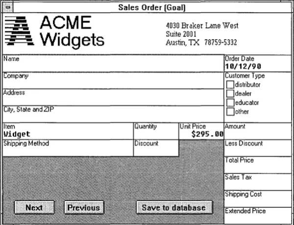
In this tutorial, you recreate the order-entry sample application,
Figure 1.1 Sales Order form from the
Order sample application
Sequence
The database files for your application-the ORDERDB database and the database's index file, ORDER.PX-are supplied with your ObjectVision software.
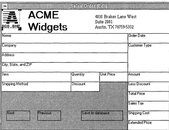
Order is a simple application designed to show you how forms,
fields, and decision trees work together. It is easy to create, and uses many important ObjectVision features, including links to external data and calculated fields. Order's Sales Order form is shown in the following figure:
ACME
Widgets
4030 Braker Lane West Suite 2001
Austin, TX 78759-5332
[image:15.478.164.464.176.406.2]Conventions and terms
The tutorial mixes explanatory information and procedures. A procedure, with steps that you are to carry out at your computer, has a pencil icon in the sidebar.
§> Your next steps: Look for this icon if you want to skip the explanations and concentrate on actual procedures (or if you prefer, read the explanations first and skip the procedures).
The key called Enter in the tutorial may be labeled Return on your keyboard or identified with a bent arrow.
Two terms refer to the process of performing an ObjectVision operation:
• Select means to position the pointer on an item and highlight it. The highlighted item will receive the next action that Object-Vision performs. For example, when you highlight a field on a form by clicking it or pressing Enter, the next action you perform applies to that field. When you select text, it displays in reverse video and is replaced by the next characters you type.
D Choose means to execute or carry out a command. If you have
already selected an item, the action of the command is applied to the selected item. For example, you choose a command on a menu by clicking it or pressing Enter. Similarly, you choose a dialog box command button by clicking it or selecting it and pressing Enter. In some cases, double-clicking an item both selects and chooses it.
Keyboard and mouse operations are listed in Appendix A.
The ObjectVision tools
ObjectVision includes four tools for developing applications:
II The Form Tool, with which you create and modify forms and
their elements
II The Tree Tool, with which you add and modify decision trees
• The Links Tool, with which you create links to external sources
Incremental development
To help you learn how to use ObjectVision, this tutorial has you recreate a sample application, Order. As you work with the tutorial, keep in mind that ObjectVision differs from other application tools in one important aspect: Instead of knowing in advance the exact details of the forms you want to create, you will be starting with a general concept of how you want your
application to work, and adding the details as you go.
When you work on your own application, you shouldn't try to get it perfect the first time. Instead, create a rough prototype. You can keep changing your prototype, each time getting a clearer idea of how it should work, until it does what you want. At that point, you can go back and add the finishing touches, like resizing fields, adding help information, inserting patterns, and so on.
ObjectVision concepts
Your applications can include standardized procedures and decision processes users need to follow when filling in the data required to complete the application. You can design applications to gather and present information for a great variety of user needs.
An application can contain either a single form or multiple forms. You can specify which portions of your applications are
completed automatically and in what sequence users complete your applications. You can also link your application to data files produced by other applications.
Your applications can automate any task that requires users to follow complex procedures and accurately capture data, thus making the task almost effortless for the user. Some typical areas for ObjectVision applications are
• Loan/ credit approval
• Insurance risk/ rate determination • Insurance claims processing • Personnel benefit administration • Customer support
Users
Forms
• Telemarketing support
• Equipment diagnosis and repair • Factory quality/yield control • Factory scheduling decisions
• Process startup / shutdown procedures • Purchasing decision support
• Tax reporting/planning decisions
ObjectVision is easy to use for both designing applications and using them.
• ObjectVision can be used to create an application for the specific requirements of an individual or a group.
Programming skills are not necessary to create an ObjectVision application. Application designers can be experienced personal computer users or systems analysts familiar with the appli-cation task. Appliappli-cation users can easily modify appliappli-cations for specific requirements .
• ObjectVision Runtime lets end users complete ObjectVision applications without letting them modify an application.
People who are familiar with an application's requirements can be involved in its design and maintenance. Application designers can easily incorporate user suggestions resulting in custom applications that meet the needs of the particular organization.
ObjectVision presents a forms interface to users because it is a familiar way to collect and display information. You can specify how your application's information displays in the forms' fields.
Form Tool
Distribution
Using forms
A stack is equivalent to a
stack of paper forms.
can be exact replicas or enhancements of existing paper forms. When you create applications for which no paper forms already exist, you can quickly design forms to contain the relevant information.
As you create an ObjectVision application, you use the Object-Vision Form Tool to define your forms. With the Form Tool, a high-level graphical interface, you specify what fields you want on a form and how those fields appear. You can adjust field attributes such as numeric formats, fonts, patterns, and borders.
After you create and save an application, you can make copies of your disk file and distribute them to users. Users can then run your application using ObjectVision or ObjectVision Runtime, because no conversion of your file is necessary.
For more information about licensing ObjectVision Runtime, see the ObjectVision Runtime brochure included with your Object-Vision materials.
ObjectVision applications automatically determine guided completion, the field sequence users follow while filling in forms. The user can interrupt guided completion at any time to open, close, or rearrange forms on the display.
The set of forms in an application is ordered in a stack. Figure 1.2 shows the stack of forms for the Order sample application. Each form is represented as an icon. Its unique title appears to the right of the icon.
Figure 1.2
Order's stack of forms
Fields
Values
4,096 is the maximum number of characters in a
field value.
Scratchpad forms
Scratchpad forms are temporary forms created
r§l Distributor Information
Fields are the blanks on your forms that contain user-entered or
automatically calculated values. You give a unique name to each ObjectVision field in your application.
You can put the same field on two or more of your forms. You might want a field on multiple forms to save users the bother of entering the same information repeatedly. For example, a client's name or identification number that must appear on all tax forms needs to be entered only once. When a field is used on multiple forms, it has the same value on all forms, regardless of which copy of the field the user actually enters the information into.
Field values are undefined until the user enters a value, Object-Vision calculates a value, or a link to external data provides a value. Any field can contain any type of value: numeric, text, or error.
A field can have only one value at a time. When the user enters a new value, the new value replaces the old one.
Figure 1.3 Scratchpad form in the
Expense sample application
Decision trees
Suppose, for example, that you are modeling your application on existing forms that do not contain all of the background infor-mation needed to calculate a value. Rather than add a field to one of your forms or create a new form, you can have ObjectVision use a Scratchpad form to prompt the user for the field's value.
You use the Tree Tool to create decision trees that define proce-dures for calculating field values. Some proceproce-dures may be simple math operations such as adding a column of numbers. Other procedures may be more complex and involve examining a variety of conditions before calculating a value.
For example, the amount of temporary insurance granted in an insurance application may be determined by a procedure that considers the applicant's age and health and type and amount of insurance requested.
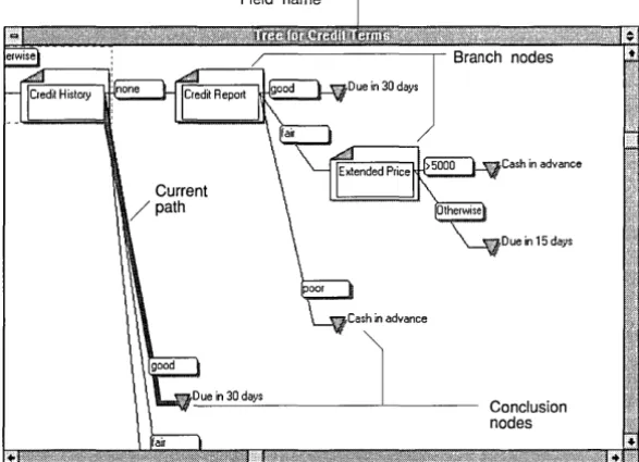
Figure 1.4 Decision tree for one of
Credirs fields
Your decision trees return the value defined by the conclusion node.
+.0
Field name
~---,-Branch nodes
- - - ' - ,
Current /path
Cash in advance
Due in 15 days
- ' V I
---1---'---
Conclusion nodesFigure 1.4 shows part of the Credit Terms decision tree from the
Credit sample application. This field calculates credit terms for a customer based on the customer's credit history and order size.
Decision trees can define a complex decision-making process by breaking it into a series of smaller steps. At each step, a single element of the tree, called a node, is evaluated.
When you create a decision tree, you define all anticipated field values as nodes in your tree. You can place one or more nodes in a tree branch, which details the logic for each anticipated field value the decision tree calculation is based on.
ObjectVision follows the branch appropriate to the evaluated condition of a field value. When ObjectVision reaches the last branch node, the decision tree defines a conclusion that results in a calculated field value.
[image:22.480.140.434.82.294.2]Tree Tool
Decision trees calculate fields automatically.
Fields
You use the Tree Tool to create and edit decision trees. The Tree Tool's cut, copy, and paste operations let you manipulate your decision trees graphically. Whenever you create a new decision tree for a field or modify an existing tree, you also change the decision-making logic associated with that field.
As the user fills in your form's required field values, ObjectVision calculates any decision tree values dependent on the user-entered values. You can create a decision tree for any field in your
application.
When ObjectVision determines which of your tree branches to follow, the actual field values are evaluated. This process is very similar to using formulas in spreadsheets that refer to other spreadsheet cells.
Your users can perform "what if" analyses simply by changing the value of a field. ObjectVision recalculates all of your applica-tion's decision trees that contain references to the changed field.
Highlights for field types ObjectVision distinguishes among fields of different types by displaying different highlights around the field border:
Overriding values
• A dashed line within a heavy line appears when a user selects one of your form's calculated fields.
• A heavy line appears when either ObjectVision or a user selects a field requiring user input.
• A field you have protected from user input displays the heavy line highlight without a text pointer.
Users can override unprotected, calculated fields in your appli-cation's forms by entering new values. When a user overrides the calculated value, the user-entered value replaces the calculated value without removing the decision tree logic you assigned to that field.
Expressions
Condition and
restore the calculated value, they can use the Field I Calculate command to recalculate the value based on the decision tree logic.
Within decision trees, you can use expressions to compute values based on a combination of other values. For example, you might need to multiply a series of numbers. You can use ObjectVision expressions that are identical in concept, use, and syntax to Quattro Pro's spreadsheet formulas.
Expressions used in decision tree conclusion nodes can contain constant values, such as "Yes" or "No." They can also contain expressions to calculate values based on other field values.
Your expressions can specify the condition that determines which branch in the tree is used. An expression can be either a constant value or an expression that computes a value. A constant value, such as "Excellent," "Good," or "Fair" can be used as a branch condition. An expression, such as ">= Total," can also be used as a branch condition.
A decision tree without branches has only one conclusion node and always returns the same value.
The syntax and use of ObjectVision expressions is compatible with Quattro Pro formulas. An expression can contain combinations of constant values, references to field values, mathematical and comparison operators (such as + and >=), and @functions (such as @INT). Like field values, expressions can contain a maximum of 4,096 characters.
Conclusions
When you use the Tree Tool to create a decision tree, you can useExternal links
ASCII files
Your applications can use external links to data as an alternative to requiring user input or computing a value in a decision tree. You can use ObjectVision's Links Tool to create, modify, or delete external links that read from and write to data files created by other applications.
You can use ObjectVision's external links in your applications to link with these data file types:
• ASCII • Paradox
• dBASE-compatible • Btrieve
• Dynamic Data Exchange (DDE) to other Microsoft Windows applications
You can create links of all five types by choosing the Tools I Link dialog box. When the Tools I Link dialog box appears, you specify the type of link you want, where the external data is, and which ObjectVision fields to connect.
ObjectVision also provides a set of @functions for links you can use in your decision trees. For more information, see Chapter 9.
When your applications link to external data, the operations your links perform observe the conventions of the application that created the data file. For example, when a user searches for an existing field value using wildcard characters, and a match for that pattern is unavailable, Paradox returns the closest matching record, and dBASE returns nothing.
Your ObjectVision applications can exchange data with ASCII files. Many popular spreadsheet, database, and word-processing applications read and write ASCII files. You can also use ASCII files for transferring data via a modem to a remote location.
Paradox
dBASE
Your ObjectVision applications make it easy for users to get existing data from Paradox files. The links you create can also either append your application's linked field values to the database or update the database's records.
After you choose the Tools I Links command, you can create, modify, or delete a Paradox link by choosing the corresponding button in the Tools I Links dialog box.
After you choose Paradox as the link type, the Link Type I Paradox dialog box appears. This is where you specify the link name and the path and file name of the Paradox file. ObjectVision reads the header of the Paradox file to locate the primary index file and the Paradox data field names.
The Paradox field names display in the Field Name list, and you can select which fields you want to connect with your Object-Vision fields. The number of links to your application is limited only by the amount of memory your system has.
You can also use the @PXOPEN, @CLOSE, and @STORE functions in your decision tree expressions to create links to Paradox. The
@TOP, @BOTTOM, @PREVIOUS, @NEXT, @CLEAR, and @DELETE
functions enable you to locate a particular record or position precisely in the Paradox file.
Your applications can be used in a multiple-user environment, where data integrity is essential. All users can use your Object-Vision application to read linked Paradox records. ObjectObject-Vision notifies users trying to save revised values if other users have already updated the same record during the current session.
Your ObjectVision applications make it easy for users to get existing data from dBASE-compatible files. The links you create can also either append your application's linked field values to the database or update the database's records.
Btrieve
After you choose dBASE as the link type, the Link Type I dBASE dialog box appears. This is where you specify the link name, the path and file name of the dBASE file, and the (optional) index file. ObjectVision reads the dBASE file header to locate the dBASE data field names, and reads the index file header to determine the indexing scheme.
The dBASE field names display in the Field Name list, and you can select the fields you want to connect with your ObjectVision fields. The number of links to your application is limited only by the amount of memory in your system.
In your decision tree expressions, you can use the same
@functions you use for Paradox when you create links to dBASE files (with the exception of @DBOPEN, which you must use to open a link to a dBASE-compatible file).
Your applications can be used in a multiple-user environment, where data integrity is essential. All users can use your Object-Vision application to read linked dBASE records. ObjectObject-Vision notifies users trying to save revised values if other users have already updated the same record during the current session.
Your ObjectVision applications make it easy for users to get existing data from Btrieve database tables. The links you create can also either append your application's linked field values to the database or update the database's records.
After you choose the Tools I Links command, you can create, modify, or delete a Btrieve link by choosing the corresponding button in the Tools I Links dialog box.
After you choose Btrieve as the link type, the Link Type I Btrieve dialog box appears. This is where you specify the link name and the path and file name of the Btrieve file. You also need to include the path name of the directory that contains the XQL data
dictionary files if the Btrieve table is an existing table.
Once the link is established, the Btrieve field names display in the Field Name list, and you can select the fields you want to connect to your ObjectVision fields. The number of links your application opens is limited only by the amount of memory in your system.
In your decision tree expressions, you can use the same
DDE
files (with the exception of@BTRVOPEN, which you must use to open a Btrieve link).
Your applications can be used in a multiple-user environment, where data integrity is essential. All users can use your Object-Vision application to read linked Btrieve records. ObjectObject-Vision notifies users trying to save revised values if other users have already updated the same record during the current session.
Windows provides the Dynamic Data Exchange (DDE) link mechanism to allow Windows applications to transfer information directly, without using ASCII files.
You can create DDE links from your application to other Windows applications such as Excel and Word for Windows.
DDE links have the advantage of transferring data automatically whenever the information source file receives a new value. With DDE links, you can seamlessly integrate your application's data with files from a variety of Windows products. You can also link your application to multiple ObjectVision applications when you need to create an application larger than the ObjectVision system limits allow.
Guided completion
When users select a field, they interrupt guided completion as defined by your Goal form.
Form status [Complete]
displays when the user has completed filling in your application:S forms.
By default, ObjectVision determines guided completion based on your application's Goal form. This feature selects only those fields requiring a user to supply a value. Users who are unfamiliar with your application need only to supply information in fields
selected by guided completion.
When a field gets its value from either a decision tree or an external link, it is omitted from guided completion. Whenever guided completion selects a field, the form containing that field appears so the user can supply a value.
A user can let ObjectVision select the next required field and form using guided completion, or they can interrupt guided
Restoring guided
completion
File I Resume quickly restores guided completion.
application name. The initial Goal form is the form occupying the top position in the stack.
During form completion, the user can interrupt guided com-pletion by manually selecting another field or another of your application's forms. After a user selects a new, incomplete form, ObjectVision determines guided completion for the newly selected form.
This user-selected form continues to be the Goal form until the user closes it, selects a new Goal form, or restores guided completion. When the user closes a Goal form, ObjectVision selects the previous Goal form as the new Goal form. To resume guided completion for the initial Goal form, the user can choose the File I Resume command.
Minimal recalculation
The Field I Calculate command determines guided completion for calculated values.
Whenever the user enters a new value or changes an existing value in your application, only those values that are based on that value recalculate. Recalculation occurs whether the user is
following guided completion or manually selecting fields.
Minimal recalculation enables users to perform "what if" analyses within your application. For example, the user can use recalcu-lation to determine the effect of changing a field's value.
When field values in your application need recalculation, Object-Vision first removes the current value of any field that is based on the changed value. Next, the new value displays in all the
dependent fields.
After the user changes a value, ObjectVision may be unable to recalculate a value for all dependent fields. When a changed value requires ObjectVision to follow other branches in your decision tree, new values may be required.
Active assistance
c
HFigure 2.1 The Sales Order form
A p T E R
2
Creating
a
form
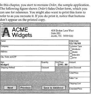
In this chapter, you start to recreate Order, the sample application.
The following figure shows Order's Sales Order form, which you
can use for reference. You might also want to print this form to refer to as you recreate it. If you do print it, notice that buttons don't appear on the printed copy.
• Create and resize the Sales Order form . • Save Myorder, the application you are creating.
Creating your form
When you're ready to create your own form, follow these four steps:
©> Your next steps: 1. Start ObjectVision, but don't select an application.
Figure 2.2 Newly created Sales Order form
2. Choose the Maximize button located in the upper right corner of the window. This button (shown at left) enlarges the window so that it fills the screen. You should maximize the window whenever you start ObjectVision in this tutorial. 3. Choose the Form command from the Tools menu. The Form I
Form Name dialog box appears.
4. Type Sales Order and then choose OK or press Enter.
The newly created Sales Order form appears, as shown in the next figure:
Also notice the size of the form, which is the default size of newly created forms. You can resize the form with the Form Tool. In the next section, you'll enlarge the form.
Resizing your form
When you position an object on a form, the size of the form increases, when necessary, to make room on the form for the new object. You can also change the size of the form manually. Now you will change the size of the Sales Order form to match the
Order sample application.
(::::..1. Using the mouse:
(§> Your next steps: 1. Move the pointer to the right border of the form; when the pointer changes to a double-headed arrow, drag the border to the right until it is close to the application window's right border. Move the left border to the same distance from the application window's left border.
2. Use the mouse to enlarge the form vertically by moving the top and bottom borders until they almost touch the appli-cation window's borders. If you position the pointer in a corner of the window, it changes to a four-headed arrow that lets you move two borders at the same time.
N ow the Sales Order form should look like the one shown in Figure 2.3 on page 26.
Or, using the keyboard:
1. Open the Sales Order form Control-menu box by pressing Alt+-(hyphen).
2. Select the Size command, then press Enter.
3. Press f-,
1',
~, or J, to select a border to change, and then press f-,1',
~, or J, to move the window border. After you move aborder, and before you press Enter, you can move an adjacent border border by pressing another arrow key. Then press Enter. N ow move two more borders and then press Enter.
Figure 2.3 Resized Sales Order form
Naming and saving your application
In the next steps, you name and save the application you are designing. The original order application included with your ObjectVision software is named Order. Be sure to name your application Myorder so you don't overwrite the sample application.
©>
Your next steps: 1. Choose Form I Close Tool to return to form completion mode. 2. Choose File I Save or File I Save As.3. After the File I Save dialog box appears type Myorder (or myorder-the case doesn't matter). ObjectVision automatically adds the extension .OVD.
4. Choose OK, or press Enter.
c
HForm objects
A p T E R
3
Creating form objects
In this chapter, you insert objects into the Sales Order form. After inserting the objects, you will define some of their properties. You will learn these ObjectVision procedures:
• Inserting fields, text elements, and a filled rectangle into the Sales Order form with the Objects commands.
• Copying and inserting fields with Edit I Copy and Edit I Paste. • Renaming copied fields with the Properties I Name/Text
command.
• Changing the label font of a text object. • Removing the border of a text object.
• Applying the same border change to another text object with the Properties I Repeat command.
• Pasting a graphic from the Clipboard.
Fields
Fields are the areas of a form that display information. Depending on how you define fields, they get values in one of three ways: The user types or selects a value, ObjectVision calculates a value from a decision tree, or an external link provides a value.
After you insert a field into your form, you can define the field's display properties (text/ numeric, selection list, button, and so on), label text, border, and the alignment of its value (left, right, or centered).
You can also protect the field from user modification, hide its decision tree from the user, attach help information to the field, or keep the field name from displaying.
Ordering your fields When you insert fields into a form, remember that the order of the fields influences guided completion of an application during form completion and should be appropriate to your application's logic. ObjectVision evaluates fields from left to right and from top to bottom, ordering the fields by the position of their bottom left corner.
Text
Rectangles
Text objects are constant text strings that are always displayed on the form. You can use a text object to identify a field or to explain its use. After you insert a text object into a form, you can define its alignment, label font, and border.
Filled rectangles can improve the appearance of forms by filling in unused areas, and can improve readability by separating fields. When you insert a filled rectangle, you select one of several patterns. After you insert the filled rectangle, you can define its border. You should avoid a fill pattern that is similar to the fill pattern used to indicate a field value override.
Lines
Graphics
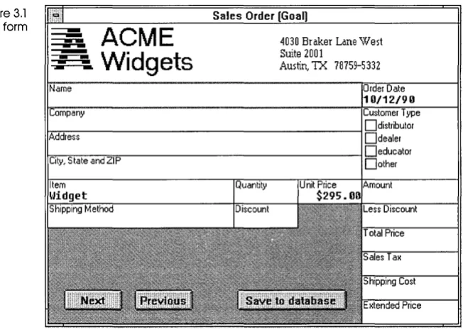
[image:38.478.105.431.324.558.2]Inserting fields
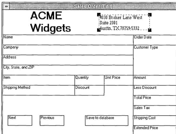
Figure 3.1 Sales Order form
Lines can be drawn on a form to emphasize certain areas. You can select one of four line thicknesses using Properties I Line Width. These line thicknesses can also be applied to the borders of a selected field, text object, rectangle, or graphic.
Graphics are visual elements you can use to help identify your forms and enhance their aesthetic appeal. Before you can insert a graphic, it must be placed onto the Windows Clipboard. Other-wise, you will see the error message,
Clipboard does not contain graphic
N ow you'll insert fields into your Sales Order form. Figure 3.1 shows the fully defined form again for you to refer to.
ACME
Widgets
4030 Braker Lane West Suite 2001
Dialog boxes
(§> Your next steps:
Figure 3.2 Objects I Field I Field Name dialog box
In this section, you'll use the following commands:
• Tools I Form, to open the Form Tool • Objects I Field, to add fields
• Edit I Copy and Edit I Paste, to add more fields
• Properties I Field, to change the names of copied fields
During the next procedure (and throughout the rest of the tutorial), you use dialog boxes to set options. Setting dialog box options involves these steps:
• Highlight the item you want (if it's not already highlighted). • Choose the OK button to carry out your settings. With the
keyboard you press Tab to highlight OK and then press Enterto
carry out your settings. You can use the mouse to click OK.
1. If Myorder is no longer loaded, choose File I Open, and then select MYORDER.OVD from the list of application files displayed. Choose Open, or press Alt+O to open the Myorder
application. The Myorder application opens in form completion mode.
2. Choose the Form command from the Tools menu. The Form Tool opens, with the Sales Order form displayed in Edit mode. Notice the Form menu in the menu bar. You use this menu to insert a~d define the form objects.
3. Choose Objects I Field. The Objects I Field I Field Name dialog box appears, as shown in the following figure:
field Name
The dialog box contains only one item, <Add New Field>. After you add fields, the field names appear in this list. 4. Select <Add New Field>. (Because <Add New Field> is
already highlighted, you can just press Enter or choose OK.) 5. In the Objects I Field I Field Name dialog box that then appears,
type Name, and then press Enter or click OK.
Now a cross-hair pointer appears on the otherwise blank Sales Order form. This pointer lets you create the Name field.
t--~ Using the mouse:
(§> Your next steps: 1. Hold down the left mouse button while you drag the cross-hair pointer down and to the right. As you do so, a dashed rectangle appears showing the size and position of the field. 2. Release the mouse button when the rectangle is the correct
size.
Note that the line surrounding the field remains dashed and that a small black square appears at each corner of the field. This indicates that the field is still selected.
You can change its size by putting the mouse pointer on one of the corners and dragging the corner to a new position. You can also change the field's position by putting the mouse pointer anywhere inside the field and dragging the entire field to a new position.
You can move the entire field by using the
1,..1-,
-7, andf-keys. You can move the lower right corner of the field by pressing Shift and anyone of the arrow keys.
U sing the keyboard:
1. Move the pointer to the left border of the form, to the appro-priate height for the top of the Name field, then press Enterto
anchor the position.
2. Press -7 and J, until the Name field is the correct size, then press Enter again when you finish.
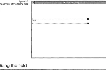
Figure 3.3 Placement of the Name field
Sizing the field
---~
---a
It's important to make a field high enough and wide enough to display its name and the largest possible value that the field can have.
If the field is linked to a database field, you must make the Object-Vision field the same width as the database field. For example, the Name field in the Sales Order form is linked to a database field that can contain up to 48 characters, so you must make the Name field big enough to contain 48 characters. If an ObjectVision field isn't large enough to contain its linked value, users won't be able to display or enter new data longer than the field size.
When you create a field, you can make it whatever size you want. If you later find that the field is the wrong size, you can easily change it:
2. When the pointer changes to a black square, hold down the
t--~ mouse button and drag the corner to the right until the field is the correct width.
3. To make a field wider using the keyboard, press Shift+ ~ to move the lower right corner of the field (and thus the right border of the field) to the right.
Testing the size After you have created a field, you should test it to make sure that it's the right size for the largest possible value it can contain. You can return to form completion mode and test the field immediate-ly after you have created and sized it, or you can wait until you have finished this section. To test the field, type the largest antici-pated field value and count the number of characters.
To return to form completion mode and test the Name field now, follow these steps:
@ Your next steps: 1. Choose Form I Close Tool.
Moving fields
@ Your next steps:
ObjectVision returns you to form completion mode. The form status, [Goall, appears after the form name in the title bar. The Name field is selected and contains a blinking text pointer. 2. Type 48 characters into one line of the field and then delete
them. If you run out of room, you need to make the field wider.
Whether or not you need to change the width of the Name field, you must now return to the Form Tool to continue the tutorial.
3. Choose Tools I Form.
As you continue creating the Sales Order form, you will insert many fields into it. You may need to move a field after you insert or paste it. Here's how to move a field:
Using the mouse:
2. Move the field to a new position and then release the mouse button. Notice that while you are moving the field, the mouse pointer changes to a cross-hair pointer.
3. Repeat steps 1 and 2 to move the field back to its proper position.
Using the keyboard:
1. Press~,~,
t,
or.t to move the selected field.2. Press Tab when you finish and you want to select another field. (In this case, of course, there aren't any other fields to select.)
Copying fields
The Company; Address; and City, State, and ZIP fields are the same size as the Name field that you just inserted. You can insert each of these fields individually, as you did the Name field, or you can create them by copying the Name field and then chang-ing their names. Here you will learn how to copy the Name field.
The copy and paste commands use the Form Clipboard, a
temporary holding place (not visible on your screen) for cut and copied form objects.
©>
Your next steps: 1. The Name field is already highlighted with dashes, so choose Edit I Copy to copy the field to the Form Clipboard.2. Choose Edit I Paste to paste the copy onto the form. You can also use the shortcut key for the Edit I Paste command, Shift+lns.
3. Use the mouse or the arrow keys to position the copy directly under the Name field. Then click or press Enter to finalize the placement of the copy.
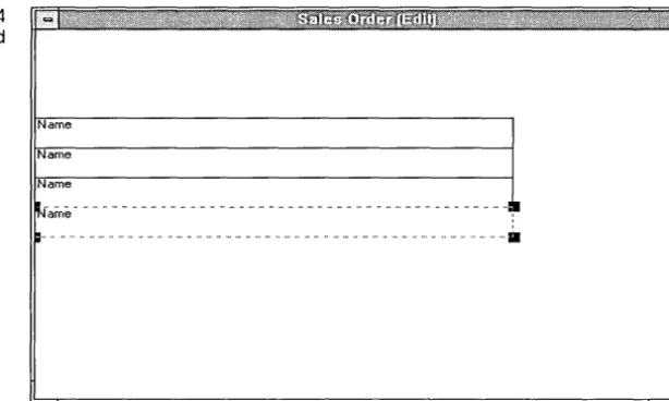
Figure 3.4 Pasted copies of Name field
Name
Name
Name
~-arrle - - - ... - .. :1
~.... .... . ... _ ... - ... ... . ... ···11
Renaming copied fields
Two commands change the name of a copied field:
• PropertieslField changes the name of the copy, while the original field-the one you copied-keeps its own name. Thus the Properties I Field command creates a new field .
• PropertieslName/Text changes the name of both the original field and the copy (thus giving a new name to an existing field). The Properties I Name/Text command changes the name of a field on every form in which it occurs, in decision trees, and in external links. (If you used the field name in help text, though, you have to change it yourself.)
Here you'll use the Properties I Field command because you want the copied field to be a new field, distinct from the original field.
§> Your next steps: 1. Select the first field you pasted-the one below the original Name field-and choose Properties I Field.
Figure 3.5 Properties I Field Name
dialog box field Name
<Add New Field>
Name
2. Choose <Add New Field>.
3. Type Company in the Field Name dialog box that appears. 4. Repeat steps 1 through 3 to rename the other two fields
Address, and City, State, and ZIP.
Adding the remaining fields
Now you will add the rest of the fields on the Sales Order form.
§> Your next steps: 1. Choose Objects I Field to add the Customer Type field,
positioning and sizing it as shown on your printed copy of the Sales Order form or in Figure 3.1. You will later format Customer Type as a check box field and add its list of possible values, but for now the field is empty.
2. Choose Objects I Field to add the Save to database field, positioning and sizing it as shown in Figure 3.1. On the finished form, the Save to database field has a rounded shape, but the field is rectangular on your form. In Chapter 5, you will change Save to database's field type to Button, which gives the field the shaded-button look.
3. Choose Objects I Field to add the remaining fields for the Sales Order form. Refer to Figure 3.1 (or your printed form) for their names, sizes, and positions. Note that the form border might resize automatically as you add objects.
5. Choose Tools I Form to return to form edit mode.
In Chapter 5, you'll define the properties of the fields.
Adding text objects
The Myorder application uses text objects to display the company name and address on the Sales Order form.
You will use these commands:
• Objects I Text, to add the text objects
• Properties I Label Font, to change the font of the text
• Properties I Borders, to remove the border from one text object • Properties I Repeat, to remove the border from the other text
object. Properties I Repeat applies the last format change you made to a selected object.
The company name and its address are two separate text objects. The first text object you add is the company name, ACME Widgets.
©> Your next steps: 1. Choose Objects I Text.
The Objects I Text I Text Value dialog box appears, and you can enter the text you want to display.
2. Type ACME.
3. Press Ctrl+Enter to move to a new line.
4. When you press Enter, the dialog box closes, the same as choosing OK. If you inadvertently press Enter, you can return to edit your text in the dialog box by choosing Properties I Name/Text.
5. Type Widgets and press Enter.
6. Using the cross-hair pointer, position and size the ACME Widgets text object where it goes at the top of the form, referring to Figure 3.1 or your printed copy of the Sales Order form.
Changing the font
In the next steps, you change the displayed font for the company-name text object.
(§> Your next steps: 1. With the ACME Widgets text object still selected, choose Properties I Label Font.
Figure 3.6 Properties I Label Font dialog box
[image:47.483.178.465.226.548.2]The Properties I Label Font dialog box appears, as shown in Figure 3.6. Your list of fonts and sizes might be different. See your Windows documentation for details about font
installa tion.
,Eont
Modet"n Roman Sct"ipt Symbol System Tms Rmn
IHelu
.size
Is
Style
D
BoldD
ItalicD
!!nderlineD
Erinter FontsWith this dialog box, you can define the font style and size you want for the text. You can also check the Bold, Italic, or U nder-lined options. Note that the default font size of the ACME Widgets object is 8. This means that the text displays in 8-point type.
2. Select font size 24. 3. Check Bold Style.
4. Choose OK or press Enter.
«:-::::..
Using the mouse:• You drag a selected field to reposition it. To resize a selected field, place the pointer on one of the black rectangles, called handles, at the corners of the object. Hold down the mouse button and drag the handle until the object is the size you want, then release the mouse button.
• You can also select multiple fields and then reposition or assign new properties for the fields as a group. For example, to move all existing fields below ACME Widgets, you can select the Name field, then hold down Shift and click the Extended Price field with the mouse. Note that all the fields you created between Name and Extended Price are now selected.
• You can also hold down Gtrl and click a field to select multiple fields. This method, unlike Shift, adds one field at a time to the multiple selection.
Using the keyboard:
• You reposition an object by selecting it and then pressing an arrow key in the direction you want to move it. To resize an object, hold down Shift while you press an arrow key. • To select multiple fields from left to right and top to bottom,
press Gtrl+Tab. To select multiple fields in the opposite direction, press Shift+Gtrl+ Tab.
Adding the address
In the next steps, you add the company address to the Sales Order form.
©>
Your next steps: 1. Choose Objects I Text.2. Type this value, pressing Gtrl+Enter for each new line. Press
Enter when you finish:
4030 Braker Lane West Suite 2001
Austin, TX 78759-5332
4. Choose Properties I Label Font, select the Times Roman (Tms Rmn) font, and set the font size to 10.
5. Choose OK.
Removing the border
In the next steps, you remove the border from the text objects you added.
~ Your next steps: 1. With the company address text object selected, choose Properties I Borders. Notice that the default value, Outline, is checked.
2. Uncheck the Outline box. 3. Choose OK.
The border has been removed from the object, but it still displays a dashed selection border. When you select another field, your text object displays without a border.
4. Use Properties I Repeat to remove the borders from the
company-name text object. First, select the company-name text object. Then you can choose the Repeat command from the Properties menu or press F4, the shortcut key.
5. Choose Form I Close Tool, then File I Save to save your work. 6. Choose Tools I Form to return to form edit mode.
Figure 3.7 Your Sales Order form with text objects
Widgets
~030-Br-aker
Lanewe-st -
-=;-:Suite 2001 : ~us.tin .. TX..7.8 75.9:5.3.32 ... .
I
S ave to databaseAdding filled rectangles
Filled rectangles can add to the clarity and attractiveness of your applications. You can use a filled rectangle to occupy a blank spot in a form or to set off fields. You can also place a filled rectangle and a field or text object in the same position to emphasize the field or text object (unless the pattern is so dark that it covers the characters). The Myorder application uses filled rectangles to fill the areas below the Shipping Method and Discount fields and between the Discount and Less Discount fields.
To add filled rectangles to the Sales Order form, you will use the Objects I Filled Rectangle command.
To remove the borders from the filled rectangles, you will use the Properties I Borders command.
@ Your next steps: 1. Choose Objects I Filled Rectangle. The cross-hair pointer appears.
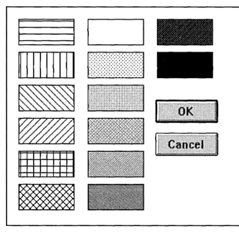
Figure 3.B
Properties I Fill Pattern dialog box
rectangle exactly fills the space between the Discount and Less Discount fields.
The resulting rectangle displays a default fill pattern. The default fill pattern doesn't match the fill pattern shown in Figure 3.1, so you can change the fill pattern by choosing Properties I Fill Pattern.
The Fill Pattern dialog box then appears, as shown in the following figure. You can choose any of the fill patterns shown.
I
I I
I
II11111111 1, ...
·::·:·:·:,::-:·:·:·:1
_111!i!!!!!!!!I!I!I!!I!!II!!!I!II!1
-1111111111
-3. Choose Objects I Filled Rectangle again.
This time, position the rectangle so that it occupies all the space from the lower left corner of the Shipping Method field to the lower left corner of the Extended Price field.
The Next, Previous, and Save to database fields show through the fill pattern (unless your monitor is unable to display the fill patterns as shown). Next you'll remove the line separating the first pattern element from the second. This line is the object's border.
s.
Uncheck the Outline box. 6. Choose OK.7. Select the first filled rectangle and choose Properties I Borders.
8. Uncheck the Outline box in the Properties I Borders dialog box. Now the border is gone and the two filled rectangles appear to be one undivided pattern.
9. Choose Form I Close Tool, then File I Save to save your work.
10. Choose Tools I Form to return to form edit mode.
Inserting a graphic
ObjectVision can display and print any monochrome bitmap you paste into your form from the Clipboard. Color bitmaps display properly in ObjectVision, but can't be printed.
You'll use the Windows Paintbrush graphics application to place the ALOGO.BMP on the Clipboard so you can paste it onto your Sales Order form.
§> Your next steps: 1. Minimize your ObjectVision application window by clicking the Minimize button, or by choosing Control I Minimize. 2. Open the Paintbrush application, which is in the Program
Manager Accessories group.
3. In Paintbrush, choose File I Open and type the complete path name for the ALOGO.BMP file copied to your ObjectVision directory during installation. For example, if you installed ObjectVision in C: \ VISION, you would type
c: \ VI S I ON\ALOGO • BMP in the File Name field. Then choose OK. 4. Select the Selection Tool from the Tool palette on the left side
of the window. It's the icon in the top row on the right side; showing a scissors and a rectangle.
S. Drag the selection rubber band around the entire outlined image.
6. Choose Edit I Copy. That copies the image to the Windows Clipboard.
You just copied the graphic to the Windows Clipboard. Next, paste a copy of that graphic into your Sales Order form:
§> Your next steps: 1. Open the ObjectVision icon by choosing Restore from the Control menu or double-clicking the icon.
2. Choose Objects I Graphic.
3. The Objects I Graphic I Save File Name As dialog box appears. Use this dialog box to give the graphic a name. Type Myalogo
and press
Enter.
4. The graphic appears as a small, unplaced field. Move it and resize it to match the Order application's Sales Order form. 5. Choose Form I Close, then File I Save to save your work. 6. Choose Tools I Form to return to form edit mode.
Note that a file named MYALOGO has been created in the current directory and given the default file extension .BMP. This is an ObjectVision file format and can't be opened in Windows Paintbrush.
The graphic object now on your form has a default border just like any other object. Remove the border using the Properties I Borders command.
Figure 3.9 A graphic in the Sales Order form
You have now inserted a graphic and all the necessary fields, text objects, and filled rectangles into the Sales Order form.
At this point, the fields in the Sales Order form have many default properties. For example, they all have the general display format type. In the next chapter, you will define different properties for many of the fields.
If you were to have a user complete the form now, ObjectVision would determine guided completion that included all the fields, because you haven't yet defined any decision trees or external links from which ObjectVision can calculate field values.
c
HField properties
A p T E R
4
Defining field properties
In this chapter, you define the characteristics of the fields you added to the Sales Order form. You will perform these Object-Vision procedures:
• Change the formats of several fields.
• Define possible values for the Shipping Method and Customer Type fields.
• Add help information to a field. • Protect some fields from user input.
When you insert a field into a form, the Form Tool gives the field a set of standard properties:
• Display type: General format (a format that is appropriate for displaying both text and numbers).
• Values alignment: Left alignment (values entered into the field are aligned at the left side of the field).
• Label font: The default character font for field names (8-point Helvetica unless you have changed it).
• Border: An outline around the field.
decision-• Line width: The thinnest line is used to draw field borders.
Once you have inserted the field, you can change any or all of these properties. In this chapter, you will change the properties of several fields in the Sales Order form.
Changing display formats
In this section, you'll change the display format type of several fields. The Form Tool provides a variety of display format types for fields so that you can choose the format mo