ABSTRACT - Integrating individual intelligent transportation systems into comprehensive platforms is a key challenge faced by transport authorities in the provision of optimal service s to users. The use of an ITS architecture encourages structured development and integration of ITS systems that leads to maximization of benefits by minimizing redundancies and maximizing capabilities. This paper presents a distributed framework for a multi-layered ITS architecture that has been designed for integrating information generated and used by future as well as existing intelligent transportation systems and applications. The iTransIT framework provides a data model that allow complex ITS domains to be successfully decomposed into a number of data layers . This multi-layered data model may be distributed across multiple systems and exploits the overlapping temporal and spatial aspects of traffic information to allow the federation of data from diverse ITS systems. Moreover, the abstractions used to compose the data model combined with the range of interaction paradigms supported by the iTransIT architecture allow interoperation between systems based on different communication technologies. This provides the framework with the flexibility to enable a gradual integration of systems over time thereby reducing integration restrictions on previously deployed systems while catering for the as yet unknown requirements of future and novel systems .
INTRODUCTION
The continued increase in traffic volumes coupled with increasingly limited space for new infrastructure development mandates that existing transport networks are employed to maximum efficiency and capacity [1].
To this end a proliferation of ITS systems have been developed and deployed throughout transportation networks. Such development has often been piecemeal with each system heavily tailored for its application-specific purpose. Consequently transport network authorities may find themselves managing an extensive series of non-interoperable ITS systems with incompatible data sets and storage techniques. Such incompatibility presents difficulties for develo ping new services required to interact with existing ITS systems and renders data re-use and sharing difficult if not impossible. One solution to this problem is to use an ITS architecture to facilitate structured systems development and integration [2].
There is significant ongoing work in the area of ITS architectures [3, 4]. The Keystone Architecture Required for European Networks (KAREN) project is of particular interest to European ITS developers while the National ITS Architecture is being promoted by the U.S. Department of Transportation. Both of these frameworks propose similar architectures promoting a separation of the physical and functional views of a system and assume that individual systems can be developed
A Distributed Framework for Intelligent Transportation Systems
René Meier*, Anthony Harrington, and Vinny Cahill
Distributed Systems Group, Department of Computer Science, Trinity College Dublin, Ireland. {rene.meier, anthony.harrington, vinny.cahill}@cs.tcd.ie
according to their respective standards for physical and functional organization.
This paper presents the iTransIT framework for an ITS architecture and its data model. The iTransIT framework has been motivated by the requirement to enable a structured approach to the design and implementation of planned ITS systems so as to ensure the interoperability of ITS systems and traffic data sets. Furthermore, the frame work has particularly been motivated by the necessity to support integration of existing or legacy ITS systems. This implies inter-system integration involving systems with different quality of service requirements and data abstractions as well as systems with diverse functional organizations, which in the case of already deployed systems may not conform to specific guidelines or standards. Reengineering such non-compliant systems is often impractical as this might cause major service disruption and typically involves considerable effort and cost.
The iTransIT framework focuses on supporting system-specific integration requirements rather than on promoting a common, system-wide organization as proposed by established frameworks such as KAREN. This particularly enables the integration of a wide variety of existing systems whose components may not map easily, i.e., without reengineering, onto standardized KAREN functions [5]. Moreover, the iTransIT framework can be considered lightweight compared to KAREN and explicitly promotes scalability through gradual integration of systems over time. Hence, iTransIT has been tailored to support the practical integration needs of existing systems that are under the administrative authority of a small number of transportation bodies and possibly confined to a subset of the functional areas identified by KAREN.
The iTransIT framework has been developed in cooperation with the Traffic Office of the Dublin City Council (DCC) in the Republic of Ireland. Detailed architecture requirements were informed by a comprehensive audit of ITS systems in the Dublin city area. Existing and planned future ITS systems were examined in an effort to identify interaction paradigms and data flows that must be supported by any overall ITS framework. The multi-layered data model at the heart of the framework has been designed as a proof of concept model capturing a variety of transportation information relevant to Dublin city that is both, of global as well as of system-specific interest.
It is expected that the increased availability of compatible and re-usable data sets from a variety of underlying ITS systems will enable higher-level management policies to be translated more easily into real world actions and systems and will facilitate the emergence of novel ITS applications and value added services. Hence, the iTransIT framework should ultimately make it easier for transport authorities to efficiently manage their transport infrastructure.
The remainder of this paper is structured as follows: Section 2 describes the rationale for the iTransIT architecture and its tiered structure. The design of iTransIT’s multi-layered data model is presented in section 3 while section 4 outlines the data flow model used for populating the data model. Section 5 presents an initial assessment of the framework and Sectio n 6 concludes this paper by summarizing our work and outlining the issues that remain open for the future.
THE ITRANSIT ARCHITECTURE
between systems and applications can be characterized according to the interaction paradigms that describe the possible information flows between legacy and iTransIT systems. These paradigms accommodate the integration of information flows and thus systems with different quality of service requirements.
ARCHITECTURE TIERS
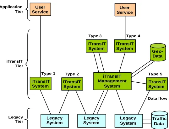
The framework for the iTransIT ITS architecture and its three tiers is illustrated in Fig. 1. The legacy tier provides for the integration of legacy systems and describes existing as well as future transportation systems that have not been developed to conform to the iTransIT system architecture and layered data model. Such legacy systems often feature a form of persistent data storage and might include systems for traffic and motorway management that have commonly been deployed in many urban environments. The purpose of the iTransIT tier is to integrate transportation systems that have adopted the iTransIT system architecture. This tier therefore comprises a federation of transportation systems that implement the iTransIT data model. The data model is distributed across these iTransIT systems, with each system implementing the subset of the overall model that is relevant to its operation. iTransIT systems maintain their individual information, which is often gathered by sensors or provided to actuators, by populating the relevant part of this multi-layered data model. However, some of the information maintained in an iTransIT system specific part of the data model may actually be provided by underlying legacy systems. Most significantly, traffic information captured in this tier is maintained with its temporal and spatial context and as a result, persistently stored data is geo-coded typically by exploiting a database with spatial extension.
The systems that may exist in the iTransIT tier can be classified according to the paradigms they exploit when interacting with other legacy or iTransIT systems. Such iTransIT systems may be purpose built to provide a specific transportation application or may be general purpose.
The application tier includes value added services that provide user access to traffic information. These services use the distributed data model and the associated context to access information potentially provided by multiple systems and might include a wide range of interactive (Internet-based) services
ranging from monitoring of live and historical traffic information to the display of road network maps. Type 1 Type 2 Type 5
iTransIT Management System Legacy System Legacy System Legacy System Data flow iTransIT System iTransIT System iTransIT System iTransIT System iTransIT System Type 4 Type 3 User Service User Service Geo- Data Application Tier iTransIT Tier Legacy
Tier Traffic
[image:3.596.241.510.430.636.2]Data
COMMON DATA MODEL
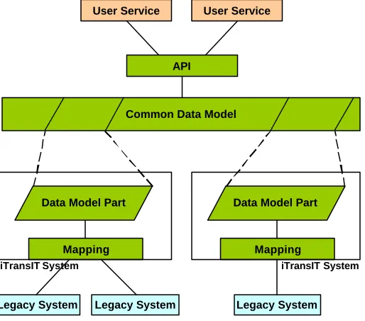
The data model, common to all iTransIT systems, is comprised of a set of potentially distributed layers and represents a central component of these systems. As shown in Fig. 2, individual iTransIT systems implement one or more of these layers (or parts of layers) and maintain the static, dynamic, live, or historical traffic data that can be stored in a particular layer. For example, a system might implement a data layer describing the current weather conditions while another layer capturing intersection-based traffic volumes might be maintained by a
different system.
An application programming interface (API) exposes this layered data model to other iTransIT systems or indeed user services by providing access based on temporal and spatial aspects of data as well as based on criteria describing different levels of detail of the ITS infrastructure. Data exchange is enabled through widely used communication technologies and query languages based on CORBA and Web Services. The complexity and diversity of the systems and data sources underlying the data model is hidden and a common view on the information and context captured across multiple systems is provided. For example, a user service might retrieve congestion information for a specific intersection and then use related
temporal and spatial context to access the weather conditions in the area.
Some of the information captured in data model layers associated with an iTransIT system may be generated or used by legacy systems. Such information is logically mapped to an underlying legacy system through data flows. These flows can be described using a set of flow classes based on the characteristics and requirements of communication links. Using these descriptions, individual iTransIT systems implement interfaces that map specific legacy data to their data layers. This approach enables the use of communication technologies that can address the requirements of particular legacy systems and their respective data flows.
ITRANSITSYSTEMS
The iTransIT framework provides a structured approach for integrating various ITS systems and hence, may naturally incorporate a number of iTransIT systems. Such systems are typically purpose-built and are therefore optimized to accommodate application or user-specific requirements. As shown in Fig. 1, the framework may incorporate a general-purpose iTransIT Management System. Both, iTransIT systems and iTransIT Management Systems conform to the architecture shown in Fig. 2 and
iTransIT System
Legacy System Legacy System User Service
Mapping
User Service
API
Common Data Model
Data Model Part
iTransIT System
[image:4.596.261.518.210.436.2]Legacy System Mapping Data Model Part
as such implement the subset of the common data model that is relevant to their respective application. However, the iTransIT Management System is the canonical application supported by the iTransIT framework and is expected to implement a major part of the data model. It typically serves as a main repository for geo-coded data generated and used by connected legacy and iTransIT systems.
iTransIT systems manage their data layers according to the common data model but often process information with different Quality of Service (QoS) compared to Management Systems. Hence, the objective of such systems might be to handle a particular data subset efficiently and to provide specific guarantees for the delivery of the data. For example, an iTransIT system may employ real-time communication technology to connect to a legacy system that is capable of supporting strong delivery guarantees. Such a system may in fact provide an iTransIT conformant real-time link for data exchange between two legacy systems that enables future data re-use by other iTransIT systems. Significantly, this scenario may initially require neither a special policy for integrated transport management nor an API for user service queries.
INTERACTION PARADIGMS
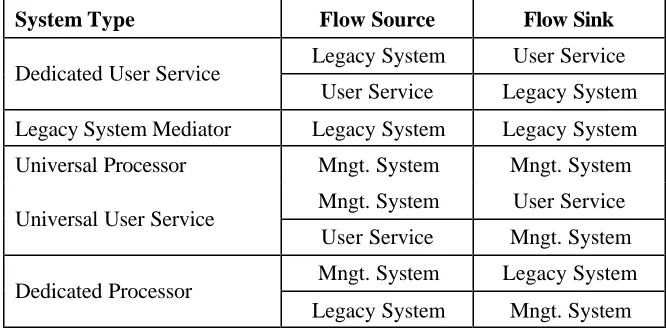
The iTransIT architecture overview shown in Fig. 1 also identifies five different roles for iTransIT systems described by the communication paradigms used to interact with other iTransIT systems, legacy systems, or user services. These paradigms essentially characterize possible flows of information and systems exploiting them are termed accordingly. An implementation of the iTransIT architecture may consist of one or more of each of these system types and specific systems may integrate one or more interaction paradigms.
System Type 1 - Dedicated User Service. These systems interface to one or more specific legacy systems and make data available to user services. Such systems can be used to provide data to or capture data from legacy systems. Data may simply be passed on or may be processed by an integrated transport management application. An example of a dedicated user service might include a remote configuration platform.
System Type 2 - Legacy System Mediator. These systems enable direct interaction between two or more legacy systems, for example, when exchanging information with bandwidth requirements that cannot be accommodated by the Management System.
System Type 3 - Universal Processor. These systems implement mechanisms that use data generated by and intended for another iTransIT or Management System. Such systems often calculate historical information using sensor information maintained in a remote data layer. For example, they may capture hourly traffic volumes in order to generate daily and monthly congestion level reports.
System Type 4 - Universal User Service. These systems may use information generated by a variety of iTransIT systems and combine them to provide “value added information” to users. For example, they may use individual journey time information in combination with weather data and road-work schedules to provide context-aware journey time estimations.
System Type 5 - Dedicated Processor. These systems implement mechanisms that re-use data from other iTransIT systems, process this information and forward the results to specific legacy systems. For example, when providing feedback on traffic volume from a novel iTransIT compatible car parking system to a legacy congestion level system.
mappings to specific legacy systems while universal processor and universal user service systems will have been designed to use the iTransIT interface to facilitate data exchange. This will facilitate the more rapid integration of these latter system types.
Table 1 summarizes the iTransIT systems roles as well as the data flows associated with each particular interaction paradigm and system type.
System Type Flow Source Flow Sink
Legacy System User Service Dedicated User Service
User Service Legacy System
Legacy System Mediator Legacy System Legacy System
Universal Processor Mngt. System Mngt. System
Mngt. System User Service Universal User Service
User Service Mngt. System
Mngt. System Legacy System Dedicated Processor
Legacy System Mngt. System
Table 1. Data flow sources and sinks for each of the system types.
THE ITRANSIT DATA MODEL
The iTransIT data model is a key component of the framework. It is a multi-layered object data model that has been designed to be scalable and inherently distributed across a range of diverse ITS systems. This multi-layered data model is built on top of a series of common modeling abstractions that have been developed to represent key aspects common to all ITS system data sets. Principal among these is the spatial aspect of ITS data that is captured by geo-coding all system data.
Extensibility. The architecture facilitates the structured development of new ITS systems and the integration of existing or legacy ITS systems. This requires that the data model be extensible to incorporate the data sets of existing, as well as those of future and as yet unknown systems.
The approach to modeling ITS data differentiates between data that is of global or general interest and data with a system or application-specific focus. Global data layers act as the foundation of the data model and contain data relating to the physical and political geography of a region as well as the transport network associated with that region. Global data can be extended by adding sub-layers for example, when including a new type of traffic detector. However, global data layers are expected to be less frequently expanded compared to system data layers. System data layers contain information associated with individual ITS systems. A layer typically represents the set of information generated or used by a specific system. New ITS systems are integrated through the composition of a new system data layer representing the data of that new ITS system.
location, identification, and role. Using this model-wide classification, data from diverse systems can be combined to provide new applications and user services.
Distribution. The data model may be distributed across multiple ITS systems with individual systems maintaining one or more layers of the overall data model. This potential distribution of layers across a series of systems effectively allows users to access elements of a certain part of the model with a specific quality of service. Hence, the concept of using a particular interaction paradigm to access a distributed data layer provides a means to share data while accommodating application specific quality of service requirements. For example, a Journey Time Estimation service that uses CCTV sensors for license plate recognition can obtain the plate id data from an iTransIT Management System using a Type 4 event-based flow whereas a real-time incident detection system using CCTV sensors might require a streamed Type 1 flow as input.
DATA MODEL LAYERS
To ensure scalability in the iTransIT data model, a multi-layered approach to modeling has been adopted. The multi-layered data model is composed of global and system layers representing regional and infrastructural data and individual ITS system data sets respectively. A cross-section of the model layers is illustrated in Fig. 3. The following three layers describe the global view of the data model. • Geographic Data Layer. This layer contains information relevant to the geographical region in which
ITS systems are deployed. This layer contains topological data and political geographic data, such as district names and boundaries.
• Transport Network Layer. This layer contains information relevant to a region’s transport network and includes information on road junctions, road links, and rail links, as well as tunnel and bridge placements. A significant part of the transport network layer captures junction and inter-connecting link elements. These elements typically capture information related to road lanes and the set of legal turning maneuvers, as well as profiles of the links connecting junctions.
• Physical Equipment Layer. This layer contains information relevant to ITS equipment and installations and includes data on signal controllers, detector loops, traffic bollards, parking meters, and variable message sign installations. Such physical equipment is characteristically modeled using abstractions describing sensor and actuator elements.
These global context layers typically contain static information or information that has a long lifetime. However, they may also accommodate dynamic or rapidly changing information. Examples of static information might include district and road network descriptions whereas dynamic information often includes data that is relevant to the operational status of ITS equipment, such as traffic volumes and congestion levels. Based on our experience with ITS systems in the Dublin city area, we have
found that systems such as a Sydney Coordinated Adaptive Traffic System (SCATS) [8, 9] and a Congestion Level application [10] may supply information for global context layers.
Physical equipment layer Transport Network Layer Geographic Data Layer
Global View Layers
Traffic Count System Journey Times System
Car Parking System Road Weather System
System View Layers
System view layers in contrast characteristically capture information of specific ITS systems that often consist of mainly dynamic data. Examples of such system view layers, again taken from the Dublin city region, are shown in Fig. 3. Of these, an Urban Journey Time Estimation system [11], might be modeled using a system layer that contains journey time values along with their respective time of day and traffic volumes. Such information may then be cross-referenced to the relevant sections of the road-network using their spatial context.
CONTEXT ABSTRACTIONS AND SPATIAL MODELING
Context abstractions are used to ensure interoperability between various data model layers and the underlying ITS systems. Developing such abstractions for a data model for the ITS domain is a complex task due to the scale and myriad of inter-relationships that exist between ITS system data sets and infrastructure elements. However, we have found that a relatively small number of abstractions suffices to decompose the iTransIT domain model.
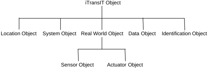
The context abstractions used in the iTransIT data model are summarized in Fig. 4. They have been designed as a series of object types using the Unified Modeling Language (UML) and include the three main abstractions for modelling global and system layers, namely Real World, System, and Data objects. Real World objects represent physical entities, such as roads and junctions, while System objects represent legacy and future ITS systems. Sensor and Actuator objects are specializations of Real World objects used to represent explicit data sources and sinks. Data objects are associated with Real World, System, Sensor, and Actuator objects and are comprised of a set of attributes that describe static or dynamic data. Data objects provide the mapping between model element values and native system data sets.
iTransIT Object
Identification Object Location Object System Object Real World Object Data Object
[image:8.596.115.482.436.562.2]Actuator Object Sensor Object
Fig. 4. Data model abstractions.
THE ITRANSIT DATA FLOW MODEL
The iTransIT data flow model supports a set of generic flow classes that are used to identify and describe key information flows between ITS system components. These classes are used to characterize the data flows that are responsible for populating the specific elements of individual iTransIT data model layers. Flow classes consist of a set of common attributes that describe their key properties. This data flow model is considered orthogonal to the iTransIT interaction paradigms since these define the interaction approach between legacy systems and ITS systems rather than a means to map information flows to specific data model elements.
Once a new data layer has been composed, for example to facilitate the integration of an additional system into the iTransIT architecture, the information flows between system components are analyzed using the iTransIT data flow classes and their attributes. Establishing the characteristics of such data flows is of central importance in the selection and design of appropriate communication technologies for mapping iTransIT data model elements onto underlying ITS systems and consequently have a direct impact on the quality of data access including retrieval latency and expected lifetime.
The following flow classes have been chosen to represent all data flows in the iTransIT framework.
Event Flow. This class represents data flows that are characteristically driven by an initiating component or source system that determines initiation time and frequency of specific information transfers, provides the information, and designates the intended system component or sink for which the information is destined. Event flows are logically asynchronous and often implemented by an asynchronous messaging protocol.
Request/Response Flow. This class represents data flows that are characteristically driven by a requesting component, i.e., by the component at which the actual information flow is terminated. This component determines initiation time and frequency of specific information transfers, implicitly designates the component for which the information is intended, and explicitly determines the information providing component. Request/response flows are typically synchronous and implemented by a synchronous protocol.
Alarm Flow. This class represents data flows that are essentially specializations of event data flows but differ in the nature of the information flow (from the user’s perspective) that they represent. Event flows illustrate information that typically describes normal system operation whereas alarm flows often indicate information that describes some fault or exception condition.
Configuration Flow. This class represents data flows that are cha racteristically generated by a source component that that may be required in order to configure another component. Such flows although asynchronous by nature, may be implemented by a synchronous means. The concept of a session is often utilised for this purpose allowing one component to establish a configuration session with another component. Such sessions may comprise several data exchanges between the parts involved.
Stream Flow. This class represents data flows that consist of sequences of related messages. Such streams may be requested by a terminating component or may be commenced by an initiating component. Since stream flows represent sequences of messages they typically depict information flows with higher volume of data compared to the previously introduced data flow classes. Audio and video data are canonical examples of stream flows. However, streams may also represent sequences of ASCII data.
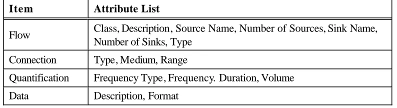
by those used to describe communication link requirements in the KAREN framework architecture [6] but have been tailored to specifically characterize information flows between ITS systems components. The attributes are grouped into four items describing different flow aspects as well as ranges of valid attribute values. However, details of these value ranges have been omitted due to space limitations.
Item Attribute List
Flow Class, Description, Source Name, Number of Sources, Sink Name, Number of Sinks, Type
Connection Type, Medium, Range
Quantification Frequency Type, Frequency. Duration, Volume
[image:10.596.99.496.181.289.2]Data Description, Format
Table 2. Attributes of data flow classes.
ASSESSMENT
The iTransIT ITS framework provides a structured approach to the design and implementation of planned ITS systems as well as to the integration of existing and legacy ITS systems. The iTransIT architecture describes a central infrastructure for capturing and storing information using spatial context thereby providing a platform for information use and re-use across a variety of ITS systems. Such systems can interoperate by sharing information through the use of the iTransIT multi-layered data model.
We have assessed this approach to information sharing by designing a multi-layered data model for Dublin city that comprises global context layers as well as multiple system context layers. This proof of concept data model accommodates the fundamental data layers required by an iTransIT Management System of this region. Using the data model abstractions introduced in Fig. 4, the geographic data layer has been modeled to describe Dublin’s districts, and the transport network layer models junctions, roads, lanes, and bus corridors, while the physical equipment layer models a set of commonly used sensors and actuators including detector loops, CCTV cameras, traffic signals, and variable message signs. A part of the modeled transport network layer is illustrated in Fig. 5. Furthermore, a number of system context layers have been added that capture information on behalf of specific ITS systems. The system context includes layers for an automatic traffic count system, a car parking system, and a journey time system.
1..n DataObject
CreationDate : Date LastModificationDate : Date RetrievalLatency : Long ExpectedLifetime : Long ConfidenceLevel : Double OutgoingJunction
idDestination : Integer
Junction Type : String
1..n 1
1..n 1
OutgoingJunctionReference idTag : Integer
ActionType : Char LinkProfile
Type : String 0..n
1
0..n
1
Lane LaneName : String DegreeOfSaturation : Double OriginalVolume : Double ReconstitutedVolume : Double
1..n 1
1..n 1
Link LinkDistance : Double numLanes : Integer SpeedLimit : Integer CongestionLevel : Double TravelTime : Double
1 1
1 1
IncomingJunction idOrigination : Integer 1..n 1 1..n 1 1..n 1 1 0..n 1 0..n 1 1..n 1 1..n 1 1 1 1 1 LocationObject
Easting : Double[] Northing : Double[] Description : String
RealWorldObject 1 1 1 1 IdentificationObject Name : String Description : String idTag : Integer id : String 1
1 1
[image:11.596.88.507.119.424.2]1
Fig. 5. Transport network layer modeling road junctions, links, and lanes.
CONCLUSIONS
This paper presented the iTransIT ITS framework, a scalable and extensible framework that enables the integration of existing and future ITS systems. The iTransIT framework divides ITS systems into three distinct classes: legacy or non iTransIT compliant systems, iTransIT systems and end user or value added services. These systems are situated at different tiers in the architecture and the relationship between legacy and compliant systems is characterized by the interaction paradigms that describe the nature of the communication flows between them. These interaction paradigms can be used to support communication flows with various quality of service requirements.
A key component of the framework is the iTransIT multi-layered data model that provides for the federation of data sets from diverse ITS systems through the use of common information abstractions. This federation is achieved by classifying system data with relevant context. This context information comprises the spatial and temporal aspects of ITS data and represents a unified mechanism for selecting and querying information from various ITS systems.
effort to identify the interaction paradigms and data flows that must be supported by a generic ITS framework. The context abstractions contained in the iTransIT data model were chosen based on the ITS domain models constructed as a result of this audit process, which has provided an invaluable grounding of our architecture design in the requirements of an actual and substantial ITS systems deployment.
The multi-layered data model at the heart of the iTransIT framework has been assessed in the form of a proof of concept model capturing a variety of transportation information relevant to Dublin city that includes global context layers as well as multiple system context layers. We are currently working towards a further evaluation of our architecture and data model based on a prototypical implementation of an iTransIT Management System. This prototype will support all three tiers and include a database with spatial extension. It will consequently feature a data model that captures information generated by underlying legacy systems and used by user services.
ACKNOWLEDGEMENT
The work described in this paper was supported by the Dublin City Council in Ireland. The authors would like to thank Dublin City Council’s Traffic Office for providing the traffic system information that made the assessment of this work possible.
REFERENCES
[1] L. A. Klein, Sensor Technologies and Data Requirements for ITS. Boston, USA: Artech House Books, 2001.
[2] J. McQueen and B. McQueen, Intelligent Transportation Systems Architectures. Boston, USA: Artech House Books, 1999.
[3] European Commission, "The KAREN Europe an ITS Framework Architecture," http://www.frame-online.net/, 2004.
[4] U.S. Department of Transportation, "The National ITS Architecture Version 5.0," http://itsarch.iteris.com/itsarch/index.htm, 2004.
[5] R. A. P. Bossom, O. LeGuellec, A. Nigro, and P. Jesty, "European ITS Framework Architecture - Functional Architecture," vol. D3.1: European Communities, 2002.
[6] R. A. P. Bossom, "European ITS Framework Architecture - Communication Architecture, Annex 1: Supporting Information for Communications Analysis," vol. D3.3: European Communities, 2000. [7] A. Dey and G. Abowd, "Towards a Better Understanding of Context and Context-Awareness," in
Workshop on The What, Who, Where, When, and How of Context-Awareness, as part of the 2000 Conference on Human Factors in Computing Systems (CHI 2000). The Hague, The Netherlands, 2000.
[8] Roads and Traffic Authority of Australia, SCATS 6.3 Operating Instructions. Eveleigh NSW, Australia: Roads and Traffic Authority of NSW Australia, 2003.
[9] B. Conolly, G. Davis, G. Francis, and K. McCallum, SCATS 6 ITS Interface: Messaging Protocol 1, version 1.3. Eveleigh NSW, Australia: Roads and Traffic Authority of NSW Australia, 2003. [10] M. Dineen, "Real-Time Display of Dublin Traffic Information on the Web," Department of
Computer Science, University of Dublin, Trinity College, Ireland, M.Sc. Thesis September 2000. [11] A. Harrington and V. Cahill, "Route Profiling - Putting Context To Work," in Proceedings of the