AIAA 95-2407
Augmented Shock Wave Severance
of Materials
Laurence J. Bement
NASA Langley Research Center
Hampton, VA 23681-0001
Morry L. Schimmel
Schimmel Company
St. Louis, Missouri
31st AIAA/ASME/SAE/ASEE Joint Propulsion Conference and Exhibit
Sheraton Harbor Island, San Diego, CA
AUGMENTED SHOCK WAVE SEVERANCE OF MATERIALS
Laurence J. Bement* NASA Langley Research Center
Hampton, VA
Morry L. Schimmel Schimmel Company St. Louis, Missouri
Abstract
This paper describes a new approach for severing or weakening a variety of materials. The technique employs embedding explosive cords into parallel grooves that are cut into a surface of a material. The cords are initiated si-multaneously to produce shock waves that progress to-ward the centerline between the cords and the lower sur-face of the material. Intersecting incident and reflected waves augment at the centerline to fail or weaken the ma-terial in tension. No harmful debris is produced on the opposite side of the material from the explosive cords. The primary focus of the effort described in this paper was to fracture the F-16 aircraft trilaminate canopy. Al-so, complete severance was achieved in 2024-T4 alumi-num plate stock. Possible applications are through-canopy egress and crew module severance from military aircraft and separation of rocket vehicle stages and pay-loads. This approach offers important advantages over explosive methods currently in use.
Introduction
A number of challenges exist in severing materials in aerospace applications. Canopy requirements for ad-vanced aircraft have seriously impacted the capabilities of emergency crew egress, under the limitations of state-of-the-art canopy jettison and through-canopy approach-es. Protection against bird strikes and the need for flat, angular surfaces for radar avoidance has driven design-ers to use stronger materials and greater thicknesses. As canopies get heavy, the 0.3-second time limit for jettison is exceeded, even with increased thrust from piston/cyl-inder mechanisms and solid rocket motors. Furthermore, the size of piston/cylinder mechanisms and solid rocket motors exceeds allowable physical envelopes within the
____________________________
*Senior Pyrotechnic Engineer, Associate Fellow, AIAA
Copyright © by the American Institute of Aeronautics and Astronautics, Inc. No copyright is asserted in the United States under Title 17, U. S. Code. The U. S. Government has a royalty-free license to exercise all rights under the copyright claimed herein for Government Purposes. All other rights are reserved by the copyright owner.
aircraft. With an increase in rocket motor thrust, down-wash is approaching the limits of human tolerance. Through-canopy ejection is currently accomplished with internally mounted explosive cords (which pepper crew-members with high-velocity debris) in material thick-nesses that are half those being considered for advanced aircraft (0.3 versus 0.6 inch). A fracturing method that would allow through-canopy ejection would eliminate ejection delays and simplify canopy system interfaces to the aircraft. The most efficient state-of-the-art severance approaches for metals, as described in1, use flexible, lin-ear, shaped charge (FLSC). FLSC, a chevron cross sec-tion explosive cord, is mounted within a bracket to a surface to be cut. These assemblies are complicated, add weight to flight systems, and are subject to damage dur-ing assembly and maintenance. A simplified system is needed to reduce or eliminate these disadvantages.
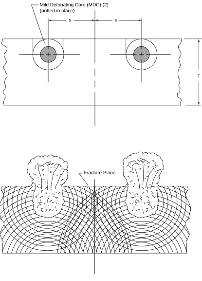
The augmented shock wave fracture/severance mecha-nism, first described in2, is shown in Fig. 1. The two ex-ternally embedded mild detonating cords are initiated simultaneously to induce explosive shock waves that propagate into the material and are reflected off the in-board surface. The shock waves augment at the center-line between the cords within the material. As these waves pass each other a strain rarefaction zone is created, which causes the material to fail in tension. This fracture mechanism was successfully applied in the explosive-fracturing of 0.75-inch thick stretched acrylic and 0.5 and 0.9-inch commercial grade polycarbonate in the reference study. This study also revealed that the proper-ties and, consequently, the fracturing characteristics of these two materials were considerably different. The stretched acrylic fractures in strata (parallel to the surfac-es) on impact from the explosive input, while the poly-carbonate is much tougher and fractures perpendicularly to the surface.
the ejecting seat, the canopy would split on the center-line, forward and aft fracture lines, and allow the newly created panels to petal open on hinge lines at the sills.
The metal severance approach envisioned for this investigation was to fracture strips of aluminum plate. Possible applications would be for aircraft capsule sepa-ration, as described in1, or, when rolled into cylinders, for the separation of rocket stages.
The objectives of this effort are twofold:
1. Primarily, to develop and demonstrate a cano-py fracture approach to allow through-canocano-py ejection.
2. Secondarily, to develop and demonstrate a simplified approach for metal severance.
Apparatus
The apparatus used in this investigation were the ex-plosive materials, aircraft canopy materials, the alumi-num, and the test fixtures. For all tests, the explosive cord was embedded by cutting grooves with hemispher-ical end mills (the diameter of the explosive cord) and potting the cord into place with room-temperature vulca-nizing silicone compound (RTV, Dow Corning 3145), assuring that a thin film of RTV was on the bottom of the groove. The groove containing the explosive cord was filled flush with the surface. The grooves cut into the F-16 canopy were accomplished by a hand-held router with a 6-inch diameter base. Reference surfaces to maintain the router perpendicularity on the surface of the com-pound curvature were achieved by bonding hard rubber strips on each side of the groove. The router was thus able to contact the same continuous line on each strip through multiple passes of the cutting operation.
Explosive Materials
The explosive materials used in this study were mild detonating cord and Dupont Detasheet. Mild detonating cord is cylindrical in cross section, like resin-core solder, with explosive material as the core. The sheath material for this study was lead. The explosive quantities are small, measured in grains/foot (15.4 grains per gram). These cords propagate at velocities of 25,000 feet/sec-ond, producing a several-microsecond impulse at pres-sures of millions of pounds per square inch. The explosive materials used were cyclotetramethylenetet-ranitramine (HMX) and pentaerythritoltetranitrate (PETN). The following are the cords used in this study and their respective diameters:
7.65 grains/foot HMX, 0.100 inch diameter 10.0 grains/foot PETN, 0.090 inch diameter 15.0 grains/foot HMX, 0.120 inch diameter
These two explosive materials have approximately the same output performance per grain, as defined in3. They were used in this study because of their availability. Ac-tual aircraft applications should use hexanitrostilbene (HNS), due to its greater high-temperature stability.
The Dupont Detasheet, which contains 65% PETN with a rubber filler, is easily molded for use in initiating the explosive cords at the corners of the fracture patterns. For these experiments, the Detasheet was pressed by hand into 0.3-inch diameter cavities machined at the cor-ners. The explosive cord centerlines were angled togeth-er from the parallel spacing into the corntogeth-er points. Thus, once initiated at any corner, the detonation fronts within the cords travel exactly side by side to the next corner point, which then initiates the next lengths of cords. Flight applications should use HNS, installed within sealed steel cups, at the corners.
Transparency materials
The materials evaluated were F-16 aircraft canopies and flat polycarbonate stock. The F-16 canopy is a tril-aminate. The material thicknesses gradually decrease from the sill to the crown. The material thicknesses at the sill were:
Acrylic 0.145 Polyurethane 0.050 Polycarbonate 0.540 Total 0.735 inch
The material thicknesses at the crown were:
Acrylic 0.095 Polyurethane 0.050 Polycarbonate 0.430 Total 0.575 inch
Panels, measuring 6× 6 and 18× 18 inches, were cut from full canopies for use in evaluating functional vari-ables. The approximate strength of the trilaminate, as de-termined by dogbone pull tests, was 5,000 pounds/inch width of material, or 10,000 psi structural strength.
Aluminum
Aluminum stock, 2024-T351 alloy and condition-ing, was from commercial mill runs. Thicknesses tested were 1/4 and 3/16 inch.
Test fixtures
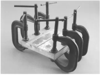
Figure 3 shows the approach used for testing 6× 6-inch panels. Four 1/8× 1× 6-inch aluminum plates were clamped along two sides. Test firings of the 18× 18-inch "mini-panels" were conducted by placing the panels on a flat surface, supporting the panels along two edges. Cra-dles were constructed for pushing out the full canopy and mini-panels to evaluate their residual strengths, follow-ing the explosive inputs. A 9-inch width mockup of a seat headrest was fabricated and used to push against the full canopy. A second headrest mockup fixture, shown in Fig. 4, was created for the evaluation of the mini-panels. A 2-inch, centerline spike with a tapered wedge was fab-ricated to split open the center fracture line, as the head rest advanced into the canopy. Also shown in Fig. 4 is the mini-panel test cradle, which supported the panel around the entire periphery. The full canopy cradle provided support at two full-width bearing lines at the aft edge and just behind the major break in the canopy profile.
Experimental Procedures
The approach for this effort was subdivided into the evaluation of each material.
F-16 canopy material
The initial explosive fracturing experiments used 6
× 6-inch panels, then a full-scale canopy, and finally 18
× 18-inch mini-panels.
The evaluation of explosive fracture variables began with the 6× 6-inch panels. The 10 grains/foot explosive cord produced an acceptable input level. Cord depth and spacing variables were evaluated by:
1. Cutting a single, variable-depth groove, increasing from 0.100 to 0.250-inch.
2. Cutting two divergent grooves, increasing the spac-ing from 0.30 to 1.00 inch between centerlines.
3. Selecting the optimum depth and spacing by con-ducting parallel groove tests.
Once the depth and spacing were established in the first two tests they were optimized in the third test series.
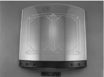
The groove pattern for the full-scale canopy test
configuration is shown in Fig. 2. Following the function-al test, an attempt was made to push through the frac-tured panels with a 5,200-pound weight and a mockup of a seat headrest; the canopy was inverted. The force was applied at the rear of the canopy, where the seat would contact during ejection. The push test did not induce fail-ure at the fractfail-ure lines. Following this test, specimens were cut from each length of fracture line and pull tested. Residual strengths were compared to the 5,000 pounds/ inch original strength of the canopy material.
Additional testing was conducted on 18×18-inch mini-panels to evaluate problems recognized in the full-scale test on fracturing through the corner areas, where the explosive cords intersected. These tests were con-ducted to make the push tests more manageable for small load-test machines. The mockup headrest was centered in the mini-panel for the push tests. The major emphasis was on intersecting the cords at the corners at 45 to main-tain cord spacing. To induce additional fracturing at the corners, "T"-shaped grooves were cut and filled with Detasheet. See Fig. 5. The pushout strengths of the mini-panels were compiled and compared.
0.875× 6× 6-inch polycarbonate
Based on the experience gained in the above effort, tests were conducted on 0.875× 6× 6-inch polycarbon-ate specimens. The first test was conducted with the 15 grains/foot explosive cord embedded into the surface. The centerline spacing between the cords was 1.5 inches. A second test was conducted by creating a trilaminate by RTV-bonding 0.125-inch cast acrylic, 0.063-inch poly-urethane and the 0.875-inch polycarbonate. Grooves were cut at the same centerline spacing into the acrylic to the top surface of the polyurethane.
Aluminum
The 1/4 and 3/16-inch 2024-T351 aluminum plates were cut into 6× 8-inch specimens for evaluation. Ta-pered plate and variable-depth and spacing groove eval-uations were conducted to determine optimums. Also, tests were conducted to evaluate metal grain direction; explosive fracture lines were set in parallel and perpen-dicular to the grain direction.
Results
F-16 canopy
A total of 57 test firings were conducted.
deeper into the polycarbonate, as shown in Fig. 6. The optimum groove depth was through the acrylic to the top of the polyurethane, the left-most point on the curve.
The divergent-groove test and subsequent 6× 6-inch panel tests provided the optimum spacing between the cords at 0.600 inch. Closer spacing produced inboard spall. Wider spacing left higher residual strengths.
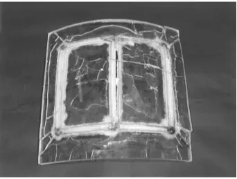
The full-scale canopy test, Fig. 7, revealed excellent fracturing had occurred in each running length between corners. The amount of crazing in the fracture areas was very uniform. The residual tensile strength averaged 460 pounds/inch for all fracture lines, or approximately 9% of the parent strength of the material. However, since no cracks propagated through the corners of the pattern, the residual strength at those points remained high.
The mini-panel test series accomplished a reduction in residual strength at the corners of the fracture pattern, as shown in Fig. 8. Figure 9 shows the results of a typical mini-panel test with explosive cord intersections that were similar to the full-scale canopy. All test specimens were essentially the same, except for number 4, which added the “T” grooves shown in Fig. 7. Considerably more fractures were induced in this specimen across the corner areas, as shown in Fig. 10.
0.875× 6× 6-inch polycarbonate
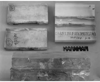
Figure 11 shows the results of tests on the
0.875-inch thickness polycarbonate. Embedding the ex-plosive cord in the specimen on the right induced some augmented shock waves in the center area, and a crack occurred below one explosive cord. The material sur-rounding the explosive was crushed away, indicating the polycarbonate toughness. The specimen on the left was the fabricated trilaminate test. Total severance was achieved without any indication of crushing at the sites of the explosive cord (the two lines drawn on the sur-face).
Aluminum
Total severance was achieved in the 1/4-inch plate under the following optimum conditions:
• 10 grains/foot explosive cord
• 0.280-inch spacing between explosive cords • A third groove (0.090 diameter, 0.050-inch deep)
was added on the inboard side centerline • The grooves were parallel to the metal grain
direc-tion for maximum efficiency
• The machined grooves reduced the strength of the plate from 16,000 to 7,200 pounds/inch, prior to testing
Total severance was achieved in the 3/16-inch plate under the following conditions:
• 7.65 grains/foot explosive cord
• Same groove spacing, including third groove • The machined grooves reduced the strength of the
plate from 11,200 to 3,500 pounds/inch, prior to testing
Conclusions
References
1Schimmel, Morry L.: “The F-111 Crew Module: Major Challenge for Thermally Stable Explosives.” Presented at the Symposium on Thermally Stable Explosives, U.S. Naval Ordnance Laboratory-White Oak, Silver Spring, Maryland. June 23–25, 1970.
2Bement, Laurence J.; Schroeder, James D.; and Schim-mel, Morry L.: “Explosive Fracturing
of Aircraft Canopy Materials.” Presented at the 1992 SAFE Symposium, Las Vegas, NV, November 2–4, 1992.
Figure 1. Cross sectional view of augmented shock wave severance principle.
Mild Detonating Cord (MDC) (2) (potted in place)
Fracture Plane
s s
Figure 2. Concept for explosive fracture of F-16 aircraft canopy to allow through-canopy ejection.
[image:8.612.136.477.434.692.2]Figure 4. Mockup of seat headrest interface used in push-out tests to split and force open fractured canopy.
[image:9.612.136.480.426.680.2]Figure 6. Results of single-cord, variable-depth in F-16 canopy material.
Figure 7. View of explosively fractured areas in F-16 aircraft canopy.
800
600
400
200
0 .112 .137 .162 .187 .212 .237
Groove Depth, inch
[image:10.612.139.477.434.695.2]Figure 8. Force versus headrest mockup displacement on mini-panel push-out tests.
Figure 9. Results of explosively fractured mini-panel test, using full-scale canopy pattern.
Test 1 2 3 4
Displacement (IN.)
Force (LBS.)
3500
3000
2500
2000
1500
1000
500
0
[image:11.612.137.479.403.662.2]Figure 10. Results of explosively fractured mini-panel test, using "T" configuration in corners.
Figure 11. Results of explosive fracturing tests on 0.875-inch polycarbonate. The explosive cord was embedded in the plate on the right and in the trilaminate test at the left. The bottom photograph is an edge view of the results of
[image:12.612.139.476.393.669.2]