warwick.ac.uk/lib-publications
Original citation:He, Wei, Luo, Xing, Evans, David J., Busby, Jonathan, Garvey, Seamus, Parkes, Daniel and Wang, Jihong. (2017) Exergy storage of compressed air in cavern and cavern volume estimation of the large-scale compressed air energy storage system. Applied Energy, 208 . pp. 745-757.
Permanent WRAP URL:
http://wrap.warwick.ac.uk/92701 Copyright and reuse:
The Warwick Research Archive Portal (WRAP) makes this work by researchers of the University of Warwick available open access under the following conditions. Copyright © and all moral rights to the version of the paper presented here belong to the individual author(s) and/or other copyright owners. To the extent reasonable and practicable the material made available in WRAP has been checked for eligibility before being made available.
Copies of full items can be used for personal research or study, educational, or not-for-profit purposes without prior permission or charge. Provided that the authors, title and full bibliographic details are credited, a hyperlink and/or URL is given for the original metadata page and the content is not changed in any way.
Publisher’s statement:
© 2017, Elsevier. Licensed under the Creative Commons Attribution-NonCommercial-NoDerivatives 4.0 International http://creativecommons.org/licenses/by-nc-nd/4.0/
A note on versions:
The version presented here may differ from the published version or, version of record, if you wish to cite this item you are advised to consult the publisher’s version. Please see the ‘permanent WRAP URL’ above for details on accessing the published version and note that access may require a subscription.
Exergy storage of compressed air in cavern and cavern volume estimation of the large-scale Compressed Air Energy Storage system
Wei He1, Xing Luo1, David Evans2, Jonathan Busby2, Seamus Garvey3, Daniel Parkes2, Jihong Wang1* 1 School of Engineering, University of Warwick, Coventry, CV4 7AL, United Kingdom
2 British Geological Survey, Keyworth, Nottingham, NG12 5GG, United Kingdom
3 Faculty of Mechanical Engineering, University of Nottingham, Nottingham NG7 2RD, United Kingdom Abstract:
Accurate estimation of the energy storage capacity of a cavern with a defined storage volume and type is the very first step in planning and engineering a Compressed Air Energy Storage (CAES) plant. The challenges in obtaining a reliable estimation arise in the complexity associated with the thermodynamics of the internal air compression and expansion processes and the coupled heat transfer with surroundings. This study developed the methodology for estimating the exergy storage capacity with a known cavern volume, as well as the cavern volume required for a defined exergy storage capacity with different operation and heat transfer conditions.
The work started by developing the mathematical models of the thermodynamic responses of air in a cavern subject to cavern operation in isochoric uncompensated or isobaric compensated modes, and heat transfer conditions including isothermal, convective heat transfer (CHT) and adiabatic wall conditions. The simulated transient air pressure and temperature were verified with the operational data of the Huntorf CAES plant. The study of the Huntorf CAES cavern confirmed the importance of the heat transfer influence on the energy conversion performance. The increase of mass storage due to the reduced temperature variation leads to an enhanced total exergy storage of the cavern. According to our simulations, within the operating range of the Huntorf plant, 34.77% more exergy after the charging and 37.98% more exergy after throttling can be stored in the cavern with isothermal wall condition than those in the cavern with adiabatic wall condition. Also, the nearly isothermal behaviour and high operating pressure in the compensated isobaric cavern resulted in the high effectiveness of exergy storage per unit cavern volume. The required cavern volume of the assumed isobaric cavern operation can be reduced to only 35% of the current cavern volume at the Huntorf plant. Finally, cavern volumes for an operational gas storage facility were used to demonstrate the methodology in estimating the exergy storage capacity, which provided an initial assessment of the storage capacity in the UK.
Keywords: Compressed Air Energy Storage, Exergy Storage, Cavern volume, Air Response
1. Introduction
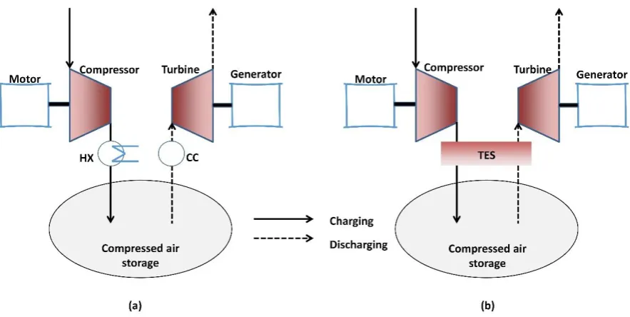
Energy storage is one of the key solutions needed to address the challenges to the power grid arising from the increasingly high renewable energy penetration [1]. Electrical energy storage provides a mechanism of decoupling the electricity generation from energy harvesting, and potentially compensating for the intermittence of power generation from renewable energy sources such as wind, solar, etc. Of the existing commercialised bulk energy storage utilities (>100 MW), Compressed Air Energy Storage (CAES) is a prominent technology. Currently, there are two diabatic utility-scale CAES plants in operation in the world. The first operational CAES plant, built in 1978, was the 290 MW (upgraded to 321 MW in 2006) Huntorf plant in Germany, using salt caverns solution-mined in a salt dome and currently operated by E.ON [2]. The second is the 110 MW plant with a rated energy capacity of 26 hours in McIntosh, Alabama. The Huntorf plant has two salt caverns, about 310,000 m3, at a depth of 600m, in which the pressure varies between 43 and 70 bar on a daily cycle [3]. The total usable volume of the McIntosh plant is approximately 19,000,000 cubic feet (about 538,000m3) and the salt cavern is at a depth of about 1,500 feet (about 450m) with the allowable pressure between 45-76 bar [4]. These two CAES systems have successfully operated for several decades. The Huntorf CAES plant has been reliably operated with excellent performance of 90% availability and 99% starting reliability [5]. The McIntosh CAES plant has maintained an average starting reliability between 91.2% and 92.1%, and an average running reliability of 96.8% and 99.5% for the discharge and charge periods, respectively [5]. In addition to diabatic CAES, adiabatic CAES (A-CAES) has been proposed in recent years to avoid using fossil fuels in the discharging of the energy storage process. Using thermal energy storage (TES), A-CAES collects and stores heat from the air compression process during the charge period, and reuses that heat instead of fossil fuels to raise the air discharge temperature at the expansion stage. Besides independence of fossil fuels, A-CAES is expected to have higher cycle efficiency than the conventional CAES plants [6-9]. In addition to conventional CAES and A-CAES, there are other CAES possibilities and innovations [10, 11].
Large-scale CAES (>100MW) usually utilises underground reservoirs which are capable of storing compressed air effectively and economically. According to the classification in [12], porous rock reservoirs (aquifers or depleted gas reservoirs) and cavern reservoirs (caverns in salt formation and low-permeability hard rock) are appropriate. Of these options for air storage, Donader and Schneider pointed out that caverns are particularly suitable for flexible compressed air storage operation with high flow rates and frequent cycles [13], because caverns have one/serval large open space/spaces compared to porous rock which consists of a large number of pore spaces. Combined with the self-healing capacity of salt-rock and solubility of salt-rock in water, which leads to easy and economical excavation of storage cavern in deep salt rock formation, salt caverns are widely used in large-scale CAES plants. The two current commercial CAES facilities were both constructed in salt-dome, in which solution-mined caverns are used for compressed air storage. In addition, low-permeability hard rock formation also is potentially suitable for underground compressed air storage. This can be achieved by either unlined rock cavern using ground water pressure and drilled water curtain or lined rock cavern with a thin impermeable liner [14].
surrounding rocks. To deal with the challenge, this study proposed a method to balance the complexity and accuracy of these estimations for the plant’s planning and design. The novel estimation method is not only simple to carry out the early-stage preliminary design without excessive cost, but also comprehensive and accurate enough to consider all the associated factors. This study examines exergy flow based on the second law of thermodynamics, and evaluates the storage capacity of the compressed air in the cavern-based CAES system. Compared to “energy”, which regards work and heat with equivalent contribution to balance the energy flow according to the first law of thermodynamics, exergy analysis focuses primarily on the maximum useful work and considers the exergy losses in the energy conversions. The exergetic analysis is valuable and it has been studied in applications with electricity output, such as the Organic Rankine cycle [15, 16], the fuel cell [17], Combined Cycle Gas Turbine [18], and other power generation processes [19-21]. These investigations used exergetic analysis and accounted for the exergy losses and efficiencies. Thus, in this study, exergy storage capacity of the compressed air indicates the equivalent maximum work deliverable during the system discharging period.
Exergy storage capacity of a cavern was studied by Garvey et al and the capacity is evaluated solely in terms of the pressure variation of the air in the cavern [22]. However, compared to the identified significance of pressure variation in the cavern to determine the exergy storage capacity, air temperature variation is significantly underestimated. For capturing the unsteady heat transfer between the air and cavern wall, three wall conditions which approximate the heat flux between air and surrounding rock are considered: 1) the adiabatic boundary condition for the cavern wall in which heat flux is zero; 2) the isothermal boundary condition for the cavern wall in which heat flux is infinite with perfect conduction through surrounding rocks; and 3) the convective heat transfer (CHT) boundary condition for the cavern wall which considers the heat transfer due to the finite temperature difference between the air and surrounding rock. Early studies developed by Osterle [23] and Skorek et al. [24] employed the adiabatic wall condition with zero heat flux through the cavern wall in the analysis of the whole CAES system performance. Alternatively, studies have developed thermodynamic models for the temperature and pressure variations within adiabatic caverns of CAES systems [25]. The work only focused on the thermodynamic responses of the reservoir with adiabatic wall in terms of pressure and temperature variations, subject to the charge/discharge cycles of CAES plants [25]. They also pointed out that the study of adiabatic reservoirs is the limiting case with negligible heat transfer across cavern walls [25]. Besides adiabatic caverns, Kushnir et al. derived another limiting case with perfect heat conduction through surrounding rock, namely isothermal reservoir [26]. Xia et al. proposed an analytical solution in a simple and unified form with the assumption of constant air density and temperature [27].
compared to the isochoric cavern, few studies have paid attention to the dynamic responses of an isobaric CAES cavern system.
Detailed numerical analysis of an isochoric underground CAES cavern were reported for the unsteady air dynamics in the past. Rutqvist at al. conducted a coupled, non-isothermal, multiphase flow and geo-mechanical numerical modelling using the TOUGH-FLAC simulator. They investigated the coupled air thermodynamics and geo-mechanical performance of the cavern and surroundings [30, 31]. Mechanical responses of salt rock to the variable thermo-mechanical loading have been explored for the design of CAES caverns. Considering the changes of air temperature and pressure in the cavern, an elasto-viscoplastic creep model and Fourier’s law of heat conduction were employed to present the material behaviour of rock salt [32]. Recently, Guo et al. developed a wellbore-reservoir model for accurately predicting the pressure and temperature of air [33]. However, these numerical analysis need excessively enhanced computational cost by numerically solving a system of governing equations through a large number of discretised elements.
This paper presents a new method for calculating the total exergy of a predefined storage volume by tracking the air dynamics in the cavern, which can also be reversely used to estimate the cavern volume subject to a target exergy storage capacity. The method suits both salt rock cavern and hard rock cavern, but requires different parameter settings. The paper starts by describing the mathematical models to reveal the air dynamics in the cavern under different operational scenarios and heat transfer conditions. To balance the computational burden and modelling accuracy, the model presents the average air pressure and temperature in the reservoir, which is coupled with the heat conduction in the surrounding rock. Furthermore, after validation of the derived models, two cavern operational scenarios of a CAES system (uncompensated isochoric and compensated isobaric cavern) and three types of cavern wall heat transfer conditions (isothermal, CHT and adiabatic conditions) are investigated. Taking the Huntorf CAES plant cavern as an example for case study, exergy storage capacity of the cavern is evaluated under different operational modes. In addition, the required volume is discussed and compared between different scenarios. Finally, potential exergy storage capacity is calculated for the UK’s Hornsea/Atwick underground gas storage facility to assess if it could be used for CAES purposes.
2. Operation of large-scale Compressed Air Energy Storage systems and different cavern operation modes
Figure 1 Illustrated large-scale CAES systems, in which Fig. 1(a) shows the conventional CAES and Fig. 1(b) illustrates the
A-CAES. HX is heat exchanger. CC is combustion chamber. TES is thermal energy storage.
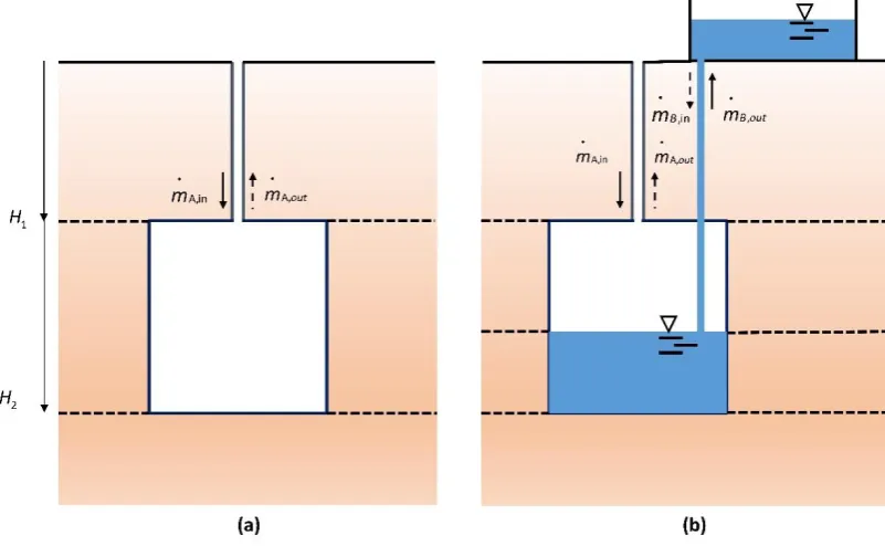
Figure 2 illustrated large-scale CAES operational systems for uncompensated isochoric air storage (a) and compensated
isobaric air storage (b).
As shown in Fig. 2(b), the illustrated compensated (isobaric) air storage is operated with the maintained air pressure in the storage using water column. The increase or decrease of the air mass in the cavern is driven by displacement of water volume in the cavern. In this configuration connecting the cavern to a surface water reservoir through a vertical shaft, a nearly constant air pressure can be operated through the whole process. In practice, a water pump is usually used so as to achieve a constant cavern air pressures higher than the hydrostatic pressure. As a consequence, the cavern can be operated isobarically at its maximum operating pressure (in relation to its depth) during the whole cycle.
3. Mathematical models of compressed air storage in CAES
As exergy is defined as the maximum useful work accomplished during a process that brings the system into equilibrium with the environment [35], the exergy variation rate of air flow can be expressed as [30]
0 0 0
[ ( )]
B m h h T s s
(1)
where B is exergy variation of air flow in J/s, and the subscript 0 denotes the property at the reference (environment, T0298 K and p01 bar) state. h is specific enthalpy in J/kg, m is mass flow rate in kg/s, T is temperature in K, is specific entropy in J/(K kg) . Using the ideal gas theory, the enthalpy difference and entropy difference of air are
0 0 0
0 0
( ); ln( ) ln( )
p p
T p
h h c T T s s c R
T p
(2)
where cp is specific heat capacity of air in J/(K kg) , R is gas constant in J/(K kg) and
p
is air pressurein Pa. The value of the gas constant is 287.06 J/(kg K) .
In cavern-based CAES systems, the energy of the compressed air stored in the cavern increases when air is compressed and injected into the storage. Thus, parts of the exergy of the compressed air due to the increased pressure converted from electricity is stored in the cavern. This is the maximum exergy capacity of the CAES in terms of the compressed air, which is the focus of this study. The exergy storage capacity of thermal energy and exergy losses in storage and discharging are not considered. According to the exergy variation rate as shown in Equation (1), the maximum exergy of compressed air stored during a full-charging in the cavern can be calculated. The maximum exergy stored in cavern after the charging period can be expressed as
max charging charging 0 0
0 0
{ (p ) [ ln( )p ln( )]}
T p
B Bdt m c T T T c R dt
T p
(3)3.1. Uncompensated isochoric air storage
For a cavern with mass inflow and outflow, according to the first law of thermodynamics, the mass and energy conservation of the control volume can be derived,
in out
dm
m m
dt (4)
( )
( )
CV
d mu
Q W mh
dt
(5)where u is internal energy, Q is heat flux, WCV is work done by the control volume, m is mass flow rate.
As internal energy u h pv in which v is specific volume of air, Equation (5) becomes
( ) ( )
d mu d mh dV dp
p V
dt dt dt dt (6)
where V is the control volume. Combining Equation (5) and (6) and considering the average air properties in the cavern [28], energy conservation becomes
( )
in in
d mh dp
Q m h V
dt dt (7)
If heat capacity of air is considered constant, Equation (7) can be presented as
( in p(in ) )
p
dp
Q m c T T V
dT dt
dt mc
(8)
To estimate the pressure variations in the cavern, the equation of state of air is
pV zmRT
(9)where z is the compressibility factor, which is used for modifying the ideal gas law to consider the real gas behaviour. For an ideal gas, the compressibility factor z is 1. Within the operational range of the Huntorf CAES plant, ideal gas assumption is nearly valid for describing the air behaviour in the cavern [28]. For simplicity, the ideal gas assumption of air is considered in this study.
Differentiating both sides of Equation (9) with respect to time, and using Equation (9), air pressure variation in the air storage can be obtained.
1
( in in out ( 1) )
dp dV
RT m RT m p Q
dt V
dt
(10)where is heat capacity ratio of air. This study considers an average value of the heat capacity ratio of air, which is 1.4.
Therefore, with Equations (10), (8) and (3), a system of equations which associate with pressure, temperature and exergy storage of air is closed, which can be solved accordingly.
In the isothermal cavern operational scenario, to further simplify the calculation of the exergy storage capacity, , exergy storage capacity of the isothermal cavern can be obtained by differentiating Equation (9) and integrating Equation (3) with the unchanged air temperature T and air volume V,
2
1
0
, 0 0
0 0
[ ( ) ln( )] [ln( ) 1]
p
V T T P p p
p
pVT
pV T p
B B B c T T T c
RT T T p
where BV T, is the exergy storage capacity of the isothermal isochoric cavern, which consists of two parts: air thermal exergy, B , and air pressure exergy, T Bp. p and 1 p are air pressure in the cavern at 2 the beginning and end of the charging.
The adiabatic cavern has zero heat exchange with the surroundings, namely Q0. Besides the isochoric constraint for the compressed air storage, (dV dt/ )V 0, Equation (9) and (11) can be further derived in the adiabatic isochoric operation. Thus, the associated pressure and temperature variations are, ,Q , , 1 ( ) ( ) ( ) ( ) ( ) in out V in
in P in V Q
V Q
P dp
RT m RT m dt V
dp m c T T V
dT dt dt mc (12)
Moreover, finite heat transfer exists in practice and the operation refers to CHT wall condition. In fact, the heat exchange rate through cavern walls can be estimated by
( )
W W W
Q h A T T (13)
where h is the average heat transfer coefficient, W A is surface area of cavern wall, and W T is W temperature of cavern wall, which is obtained by solving the heat conduction in the surrounding rock. In this study, the cavern wall is assumed to be a “two-sided wall” which is an interface between two regions of the compressed air and surrounding rock with negligible thickness.
Because the temperature penetration depth is relatively small compared to the depth of the cavern and only the average air properties considered in the cavern, the heat transfer in the rock is assumed to be one-dimensional thermal conduction in radial direction [12, 26, 27], and a long cylindrical cavern shape is considered [36]. Thus, the heat conduction equation is
, 0 1 ( ) , - ( ); , s s
s p s s
s
W s W W s
dT T
c k r
dt r r r
T
r r k h T T r T T
r (14)
where s and cp s, are density and heat capacity of surrounding rock. r is mean radius of cavern. W k s is heat conductivity of surrounding rock. T is the temperature of surrounding rock. s
With the isochoric constraint for the air volume variation, therefore, the model of air pressure in the isochoric cavern with the CHT wall is
1
(dP)V [ RT min in RT mout ( 1)h A TW W(W T)]
dt V (15)
Thus, the dynamic model of air temperature can be obtained
( ) ( ) ( )
( )
in
W W W P in V
V
P
dP
h A T T m c T T V
dT dt
dt mc
3.2. Compensated isobaric air storage
Similarly, exergy storage capacity of the isothermal compensated isobaric air cavern can be analytically obtained by integrating Equation (3) with constant air pressure
p
and constant air temperature T2
1 0
, ,T , 0 0
0 0
[ ( ) ln( )] [ln( )]
V
T p
p T p p T p p
V pVT
pV T p
B B B c T T T c
RT T T p
(17)
where Bp T, is the exergy storage capacity of the isothermal isobaric cavern. V and 1 V are the volume 2 of the compressed air in the cavern at the beginning and the end of the charging.
Because of the existence of the brine which is connected to the pond at ground level and contacted with the compressed air in the cavern, heat transfer naturally occurs between the air and brine. Isothermal and CHT conditions are considered between the air and brine due to the high heat exchange rate. Therefore, adiabatic cavern is not considered in simulating the air responses in the compensated isobaric air storage, and only models of the CHT and isothermal cavern walls are derived in the further investigation.
Due to the existing flows of brine in the air storage, in the compensated isobaric air storage, mass conservation and energy conservation of brine should be considered and coupled with those of air mass flows. Therefore, similar to the analysis of air mass balance above, mass variation of brine with respect to time is
, ,out
B
B in B dm
m m
dt (18)
where mB in, and mB out, are inflow and outflow rates of brine. In addition, temperature variation of brine can be expressed as
,
, , ,
,
,
( )
( )B p p B B in p B B in B B p B
Q m c T T
dT
dt m c
(19)
where Qp B, is heat flux to brine, T is temperature of brine. It includes the heat flux between wall and B brine, QWB,
( )
WB WB WB WB B
Q h A T T (20)
where T is temperature of the wall connected to brine, WB h is the average heat transfer coefficient WB between brine and the wall. And that from air to brine, QBA.
To approximate the temperature of cavern wall connecting with brine, temperature variations are also considered. Due to the substantial depth of the cavern from the surface, heat conduction of rock is only considered in the region which has the same depth as the cavern. As the cavern is filled with both air and brine, a quasi two dimensional heat transfer model is used in the region
,
1
( ) ( )
s s s
s P s s s
dT T T
c k r k
dt r r r z z
Thus the boundary conditions for Equation (21) becomes
0
1, 2
, - ( ); ,
0; , 0;
s
W s W W s
s s
T
r r k r h T T r T T
r
T T
z H z H
z z (22)
where H and 1 H are the height of air and brine occupied volumes in the cavern as shown in Fig. 1. 2 In CAES with compensated isobaric air storage, besides heat transfer between air and cavern walls, heat exchange between compressed air and brine through the water-air interface also plays a significant role. The heat flux between the air and brine is
( )
BA BA BA B AB
Q h A T T Q (23)
where h is the average heat transfer coefficient and BA A is area of air-water interface which can be BA approximated by.
2
BA W
A r (24)
The cavern is filled with compressed air and brine, which is
B
c B
B
m mRT
V V V
p
(25)
where V is the volume of brine in the cavern, and B B is the brine density. V is cavern volume. Due C to the constant cavern volume V , the variations of air volume and brine volume in the cavern satisfy. C
(dV dt/ )p dVB/dt (26)
When the density of brine is considered as a constant value, volume variation of brine in the cavern is,
, ,out B in B B
B
dV m m
dt
(27)
Therefore, pressure and temperature variations at this operation can be obtained accordingly,
, ,out ,
1
( )p ( in in out ( B in B ) ( 1) P B)
p B
dp p
RT m RT m m m Q
dt V
(28)
,B ( ) ( )
( )
in
p P in p
p
P
dp
Q m c T T V
dT dt
dt mc
(29)
in which (dp dt/ )p is controlled by mass flows of brine and expected to be nearly zero. Therefore, a system of Equations (28), (29) and (3) is capable of calculating the pressure, temperature and exergy stored of the compressed air in the compensated isobaric cavern.
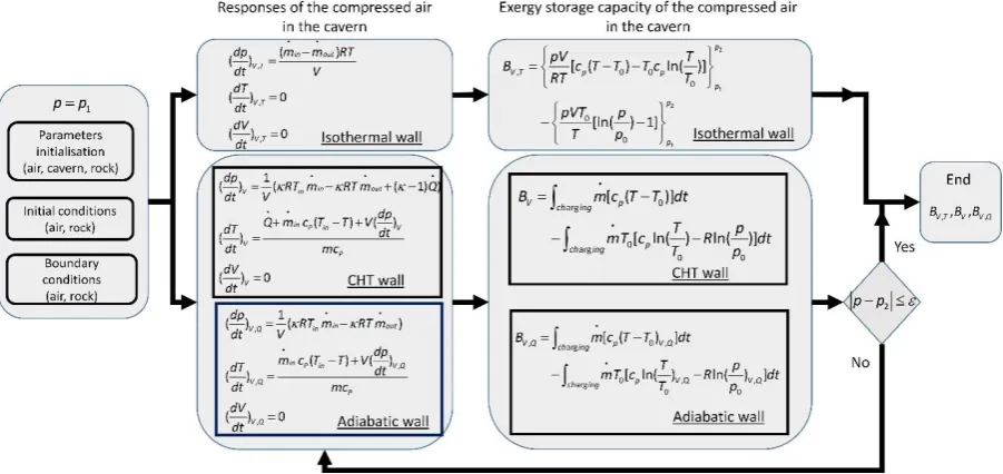
Using the derived models of the air responses in the storage, the exergy storage capacity of the cavern can be evaluated in different operational scenarios. First, for an uncompensated isochoric cavern, a flowchart of estimating the exergy storage capacity in isothermal, CHT and adiabatic cavern wall conditions is plotted in Fig. 3. It begins with the initialisation of parameters, initial conditions and boundary conditions. Exergy storage capacity of the isothermal cavern wall condition, BV T, , can be estimated by analytic expression as shown in Equation (11). For the caverns with CHT and adiabatic wall condition, numerical integration is used for estimating the exergy storage capacity with the transient pressure and temperature during the charging period. When the air pressure in the cavern reaches the maximum operating cavern pressure, the system charging finishes and the maximum exergy storage capacity of the cavern is reached after the full-scale charging.
Figure 3 Flowchart of estimating the exergy storage capacity of the uncompensated isochoric air storage. Detailed steps
with equations considering the isothermal wall, the adiabatic wall and the CHT wall conditions are included in the flowchart.
Figure 4 Flowchart of estimating the exergy storage capacity of the compensated isobaric air storage. Detailed steps with
equations considering the isothermal wall and the CHT wall conditions are included in the flowchart.
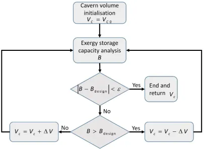
With the method of predicting the exergy storage, more accurate cavern volume subject to the system specifications can be calculated. The calculation loop of the cavern volume is plotted in Fig. 5. Based on the prediction of the exergy storage capacity, the calculation loop uses the perturbation method to find the appropriate cavern volume. With an initialised cavern volume, the iteration of the calculation starts. At every iteration, if the estimated exergy storage capacity is larger than the design value, a smaller cavern volume is updated for the next iteration. Otherwise, a larger cavern volume is searched. Until the desired exergy storage is satisfied, the calculation of the cavern volume is finished.
Figure 5 Flowchart of calculation loop of the cavern volume subject to the CAES system specifications. The flowchart can be
[image:14.595.104.510.432.728.2]5. Modelling validation of the dynamic air responses in cavern
Before the estimating process of the exergy storage capacity and cavern volume, in order to investigate the cavern operational scenarios with the CHT and adiabatic wall, this section contributes to validation of the numerical models of the air responses in the cavern. In the simulation, heat capacity of air is constant in the calculation at each time step. To approximate the real gas effect of air, after the calculation at the end of each time step, heat capacity of air is updated using software
CoolProp based on the current pressure and temperature [37], which is used for the calculation in next
time step. These models are implemented in MATLAB/Simulink.
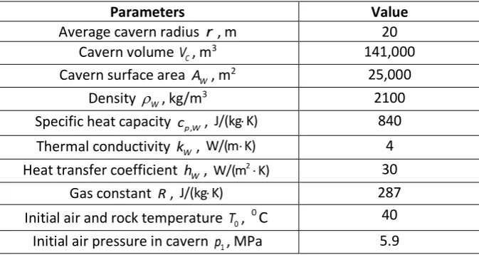
As there is no experimental data for a compensated isobaric air storage cavern available, at the early stage, only trial test data of the Huntorf plant is used to validate the dynamic models of varying air pressure and temperature in the uncompensated isochoric gas storage [27, 38]. Several parameters are used in the validation and listed in Table 1 which are from [26, 27]. The current model uses the average heat transfer coefficient and assumed that the heat transfer coefficient is independent from the temperature differences. This assumption has been adequately validated in [26], as the wall conductive heat resistance and the substantial volume of cavern significantly improve the steadiness of flow and heat transfer, and reduce the effect from its variations with time.
[image:15.595.130.467.579.758.2]A mass flow rate profile in a 24-h window is shown in Fig. 6, which is used as input variables for the simulation. The inlet air temperature at the three periods of non-zero inflow rates are 50.96 oC, 45.95 oC, and 49.08 oC, respectively [27]. The simulated pressure and temperature variations are plotted in Fig. 7(a) and 7(b) respectively. According to the results, simulated pressure and temperature variations follow closely to the test data of the trial operation of Huntorf CAES plant. Although there are slight deviations between the simulated air temperature and the operational data, the modelling successfully simulated the variation trend of the air temperature during operations of charging, storage and discharging. Using a similar model, Kushnir et al. also found that the span of the measured temperature variations are slightly smaller than the simulated values [26]. Due to the uncertainties in the lumped heat transfer model in terms of the average values of both heat transfer coefficient and area, the discrepancy may occur.
Table 1 Parameters of the Huntorf CAES plant (The values are used in modelling validation and the air pressure and
temperature in dynamic modelling uses the test data of the Huntorf plant gained during the initial trial test. [26, 27]).
Parameters Value
Average cavern radius r , m 20
Cavern volume V , mC
3 141,000
Cavern surface area A , mW
2 25,000
Density W, kg/m
3 2100
Specific heat capacity cp W, , 840
Thermal conductivity k , W 4
Heat transfer coefficient h , W 30
Gas constant R, 287
Initial air and rock temperature T , 0
0C 40
Initial air pressure in cavern p , MPa 1 5.9
J/(kg K) W/(m K)
2
Figure 6 Mass flow rate of the air to cavern in the Huntorf plant during the trial test [27, 38].
Figure 7 Validation of dynamic modelling of air pressure in (a) and temperature in (b) with test data of the Huntorf plant
during the initial trial test.
6. Case studies of exergy storage capacity of cavern and cavern volume in different cavern operational scenarios and heat transfer conditions
The mathematical models and methods above are proposed to estimate the exergy storage capacity of a cavern with known volume or explore the required cavern volume subject to a capacity target. The general approach can be used in assessing the cavern at any stage of the life cycle only if the boundary conditions and initial conditions are set properly. The case studies in this section assume the cavern has re-equilibrated with its surroundings before the air injection. Additionally, the case studies also assume negligible mass leakage and unchanged cavern volume in both operational scenarios.
[image:16.595.78.507.414.559.2]Depending on different CAES systems and operations, storage capacity of air exergy in the cavern varies. In this section, taking the Huntorf CAES plant as a case study, exergy storage capacity of the compressed air in the cavern are evaluated in different operational scenarios and heat transfer conditions. The calculations are carried out with operating parameters of the combined two Huntorf salt caverns are used, which is similar to the approach used in [28]. These parameters are listed in Table 2 which are from [3, 27, 28]. For the cavern used for gas storage, range of operating pressure is restricted. The selection of maximum pressure is determined by rock mechanical tests of the halite, the cavern depth (thickness of overburden) and temperature [39]. The minimum cavern operating pressure is usually set at the expected transmission pipeline pressure [40].
Table 2 Operating parameters of the Huntorf CAES plant [3, 27, 28] (These parameters are used for the case study of
Huntorf CAES plant).
Parameters Value
Cavern volume V , mC
3 300,000
Minimum cavern operational pressure p , bar 1 43 Maximum cavern operational pressure p , bar 2 70
Air temperature at cavern inlet T , K in ~323 Cavern wall initial temperature T , K 0 ~323
Average cavern radius r , m 20
Heat transfer coefficient h , W 30
Compressor mass flow rate m
, kg/s 108
Assumed cavern surface area A , mW
2 50,000
To evaluate the exergy storage capacity of the Huntorf cavern operated in the uncompensated isochoric air storage, charging process from the minimum cavern operating pressure to the maximum cavern operating pressure is selected. Three cavern wall conditions in the uncompensated isochoric operational mode, isothermal, CHT and adiabatic conditions, are compared to show the difference in the exergy storage capacity after the fully charging process. The pressure and temperature of air in the cavern are plotted in Fig. 8, and the exergy storage capacity of the cavern with the isothermal cavern wall, adiabatic cavern wall and CHT cavern wall are listed in Table 3. In the simulation, operating parameters of the system with the CHT cavern wall are based on the parameters listed in Table 2.
According to the results in Fig. 8(a), the charging process starts at the minimum operating pressure and ends at the maximum operating pressure in all the three cavern operational scenarios. Different cavern wall thermal condition leads to the varied duration of the charging period. In addition, temperature of the air is varied significantly as shown in Fig. 8(b). Particularly, the varied temperature of the CHT wall is also plotted. The wall temperature is not constant but it changes slowly compared to the air temperature in the cavern due to the thermal inertial of surrounding rocks. Thus, certain amount of heat is lost by transferring into the surroundings due to the unsteady finite temperature difference.
2
Figure 8 Air pressure in (a) and temperature in (b) of air in the cavern during the charging period of the Huntorf CAES plant.
Three wall conditions (isothermal, CHT and adiabatic) are considered during the system charging in the case study of the Huntorf CAES plant.
Furthermore, the results of the charging duration and the maximum exergy storage capacity in Table 3 clearly indicate that the cavern wall thermal condition significantly affects the exergy storage of a CAES system. With the selected input air operations, cavern with isothermal wall is capable of storing the maximum exergy among the three cavern wall conditions. Compared to the exergy storage in the cavern with adiabatic wall, within the same storing pressure range, 34.77% more exergy after the charging and 37.98% more exergy after throttling can be stored in the cavern with isothermal wall.
[image:18.595.72.524.648.749.2]Actually, during the charging period in the caverns with isothermal and CHT wall conditions, although certain amount of heat is lost to the surrounding rock, mass storage in the cavern is significantly enlarged due to the lowered temperature. Because the temperature of air in the cavern is maintained constantly and will not increase due to the enhanced pressure, the maximum mass of air can be injected and stored in the cavern. This largest mass storage also determines the longest charging period. In contrast, due to the temperature increase of air in the cavern with CHT wall and adiabatic wall, losses of mass storage occur. It is also the main reason to the varying exergy storage capacity in the three caverns.
Table 3 Exergy storage capacity of the Huntorf cavern with the isothermal wall, the CHT wall and the adiabatic wall
conditions (The cavern is operated in the uncompensated isochoric mode.)
Cavern wall type Isothermal wall CHT wall Adiabatic wall Maximum exergy
stored, MWh
838 711.1 603
Charging time, hrs 22.47 18.97 16.05
Mass stored, kg 8,736,336 7,375,500 6,240,240
Average input exergy rate, MW
Exergy stored after throttling, MWh
782.6 664.5 567.2
[image:19.595.80.520.72.100.2]In the realistic cavern with the CHT wall, mass flow rate of the air can be controlled to reduce the loss of maximum exergy storage. Three selected mass flow rates, namely 50, 200 and 500 kg/s, denoting low, medium and large mass flow rates, are used to evaluate the effects of the flow rate on the maximum exergy storage capacity. The results are listed in Table 4 and the parameters in the simulation are from Table 2. It indicates that with the increase of mass flow rate both the maximum exergy and mass storage stored decrease. Due to the limited heat transfer rate and the large thermal inertia of the surrounding rock, there is no sufficient time to transfer heat of the compressed air to the surroundings. Consequently, the cavern operation is more close to the adiabatic cavern. Conversely, when the mass flow rate is very low, sufficient time allows the finite heat transfer rate to effectively minimise the air temperature variation. Therefore, the cavern operation with low mass flow rate is more close to the isothermal cavern operation.
Table 4 Effect of mass flow rate on exergy storage capacity of the Huntorf isochoric cavern with the CHT wall condition.
Cavern wall type CHT wall CHT wall CHT wall
Mass flow rate, kg/s 50 200 500
Maximum exergy stored, MWh
746.0 682.9 646.1
Mass storage, kg 7,747,000 7,075,000 6,689,00
At the stage of planning and designing a CAES system, volume estimation is influenced by the heat transfer conditions of the cavern wall as well. Following the calculation loop of cavern volume, using the targeted exergy storage capacity of the cavern with CHT wall as shown in Table 3, the required volumes of cavern are compared. To achieve the same exergy storage capacity after the charging period, the estimated volumes of caverns with both isothermal and adiabatic walls are listed in Table 5. Because of the high effectiveness of the cavern with isothermal wall in exergy storage, the least volume of cavern is required to meet the same exergy storage capacity. With the selected inflow air operating conditions, about 38.82% volume increase is needed for the cavern with adiabatic wall to achieve the same exergy storage capacity.
Additionally, comparing the three cavern wall heat transfer conditions in Table 5, with the same exergy storage capacity, mass storages are close. Therefore, in the uncompensated isochoric cavern with the constrained pressure variation, mass storage is the dominant factor for the exergy storage capacity. With the similar mass storage, although transient temperature varies, the stored exergy tends to be close. If the pressure range is used to determine the system operation of CAES, due to the air temperature significantly affects the allowable mass storage in the cavern, heat exchange becomes important. Therefore, for meeting the designed exergy storage capacity, the required cavern volume varies significantly in different cavern heat transfer conditions.
Table 5 Required cavern volumes of different cavern wall operations in the isochoric mode to achieve the same exergy
storage capacity of the Huntorf CAES plant.
[image:19.595.71.527.333.406.2]Maximum exergy stored, MWh
711.1 711.1 711.1
Charging time, hrs 19.07 18.97 18.91
Mass storage, kg 7,414,416 7,375,500 7,352,208
Required cavern volume, m3
~255,000 ~300,000 ~354,000
[image:20.595.70.525.72.156.2]To indicate the potential performance of the air storage in the compensated isobaric cavern, furthermore, a case study of a compensated isobaric storage is developed using the Huntorf’s specifications. Based on the dynamic models derived, the estimation of the exergy storage capacity can be carried out. The parameters used in the simulations are listed in Table 6. In the case study, the maximum air storage volume is assumed to be 90% of the total cavern volume and the minimum air volume in the cavern is 10% of the total cavern volume. It should note that the minimum and maximum operational volumes are determined by the local condition of cavern, and the method can be used for other operational volumes. Therefore, in this case study, the full charging period of the CAES system with the compensated isobaric cavern starts at the air volume which is 10% of the cavern volume and ends at the volume equivalent to 90% of the cavern volume. The operating pressure of air is assumed to be the maximum operating cavern pressure, 70 bar. Inlet operating conditions of air and cavern parameters are same to the Huntorf cavern.
Table 6 Parameters used in simulating the Huntorf CAES system with the consumed compensated isobaric cavern [3, 28,
29].
Parameters Value
Cavern volume V , mC
3 300,000
Initial volume of air V , m0
3 30,000
Initial volume of brine VB,0, m3 270,000
Maximum cavern operational pressure p , bar 2 70 Air temperature at cavern inlet T , K in ~323
Cavern wall initial temperature T , K 0 ~323
Cavern mean radius r , m 20
Density of brine B, kg/m
3 1,190
Specific heat capacity of brine cp B, , 4,200
Heat transfer coefficient between air and wall h , W 30 Heat transfer coefficient between brine and wall hBW, 743.12
Heat transfer coefficient between air and brine h , AB 1,531 Compressor mass flow rate m
, kg/s 108
Fig. 9(a) plots the volume variations of air and brine. The temperature variations including both fluids and the wall connecting to them are plotted in Fig. 9(b) and 9(c). As shown in Fig. 9(a), the volumes of air and brine are mainly controlled by the mass flow rate of brine. Due to the inflow of air, the air pressure tends to increase, which results in the brine outflow triggered by the pressure gradient. In this way, the pressure of air in the cavern is maintained. Furthermore, because of the existence of brine in the cavern, sufficient heat transfer between the air and brine significantly reduce the air
J/(kg K)
2
W/(m K)
2
W/(m K)
2
[image:20.595.90.509.412.649.2]temperature variation, as indicated in Fig. 9(b). Air temperature quickly reduces to less than 30 and gradually increases with a slow rate, which is caused by the large thermal inertia of surrounding rock. Compared to air temperature variation, the temperature of brine slowly increases and drives the similar increasing rate of the wall next to brine.
From the results shown in Fig. 9(b) and 9(c), higher heat transfer rate between air and brine, make the process nearly a constant temperature isobaric cavern at this operation. The air temperature is close to the ambient temperature through the whole charging process. The overall performance of the cavern as listed in Table 7 also validate the nearly isothermal cavern behaviour of the cavern with CHT wall condition. In practice, the compensated isobaric cavern connecting with water column has the advantages in both storing pressure and temperature. The exergy storage capacity of the Huntorf cavern operated in the compensated isobaric operational mode is much higher than that in the uncompensated isochoric operational mode. This is because of the significantly enhanced storing pressure and the mass storage of air in the cavern. About 260% of the mass storage of the compressed air in the uncompensated isochoric cavern can be stored in the same size compensated isobaric cavern. Therefore, the exergy storage capacity of isobaric Huntorf cavern will increase to more than two times of the maximum exergy stored in the isochoric cavern.
Figure 9 Volume variations in (a) and temperature variations in (b) and (c) of air and brine in the Huntorf CAES plant with the
assumed compensated isobaric cavern.
According to the high heat transfer rate between air and brine in the cavern, the isobaric mode is capable of reducing exergy loss at the high mass flow rate. Three mass flow rates, 50, 200 and 500 kg/s, are selected to evaluate their effects on the maximum exergy storage capacity. The results are listed in Table 8 and the parameters in the simulation are from Table 6. Although the increase of the mass flow rate reduces the maximum exergy storage capacity, the exergy loss is very low. According to the results shown in Table 8, only 1.5% exergy is lost compared to the isothermal operation when the mass flow rate is 500 kg/s. Therefore, the isobaric operational mode allows the fast charging process with negligible decrease of the maximum exergy storage.
Although compensated isobaric cavern will need high capital and maintenance cost for the brine injection and withdraw, the required cavern volume will be significantly reduced because of the efficient exergy storage per unit volume. Taking the isochoric CAES cavern with the CHT wall as a reference, according to the results shown in Table 9, only approximately 35% of the Huntorf cavern’s volume is needed to achieve the same exergy storage capacity in the isobaric cavern operational
o
[image:21.595.78.513.344.508.2]scenario. Besides, the compensated isobaric cavern operation is capable of discharging at the maximum operating pressure. The constantly high discharging pressure eliminates the necessity of the throttle valve at the outlet of the cavern and leads to the high cycle efficiency as well. Therefore, the trade-off between the cost increase due to the high quality cavern and the cost decrease due to the cavern volume reduction needs to be studied for the real compensated isobaric CAES applications.
Table 7 Exergy storage capacity of the assumed compensated isobaric Huntorf cavern with the isothermal wall and the CHT
wall conditions.
Cavern wall type Isothermal wall CHT wall
Maximum exergy stored, MWh 1,983 1978
Charging time, hrs 50.52 50.4
Mass storage, kg 19,642,176 19, 595,520
[image:22.595.71.521.332.404.2]Average input exergy rate, MW 39.25 39.24
Table 8 Effect of mass flow rate on exergy storage capacity of the assumed Huntorf isobaric cavern with the CHT wall condition.
Cavern wall type CHT wall CHT wall CHT wall
Mass flow rate, kg/s 50 200 500
Maximum exergy stored, MWh
1,979 1,970 1,954
Mass storage, kg 19,602,000 19,519,200 19,350,000
Table 9 Required cavern volume of the Huntorf cavern with the isothermal wall and the CHT wall in the assumed isobaric
mode to achieve the same exergy storage capacity.
Cavern wall type Isothermal wall CHT wall
Maximum exergy stored, MWh 711.1 711.1
Charging time, hrs 18.11 18.11
Required cavern volume, m3 ~107,550 ~108,000
6.2. Underground gas storage cavern at Hornsea, UK and the CAES potential
In this section, the method of estimating the exergy storage is applied to an existing underground gas storage cavern at Hornsea (Atwick), predicting the facility’s potential in practical CAES applications. . Hornsea was the UK’s first major purpose built underground gas storage facility, with nine storage caverns, providing 325 million cubic metres of usable gas storage space. The facility could potentially be used for CAES, so do other underground gas storage facilities in the UK. Thus the Hornsea is selected as a case study to initially assess the storage capacity of compressed air storage in the UK. Both cavern operational scenarios are considered in estimating the exergy storage capacity. The parameters of the Hornsea/Atwick gas storage facility are listed in Table 10 [41-44]. Results of the two cavern operational scenarios are listed in Table 11 and 12 respectively.
facility. Additionally, if the cavern is operated in the compensated isobaric way, the total exergy storage capacity of the Hornsea/Atwick increases to about 66,000 MWh. It should note that besides the exergy storage of compressed air in the underground facility, thermal energy storage also possibly will be stored in the CAES plant. It indicates more work which is deliverable during the peak-time. This case study of the underground gas storage cavern at Hornsea (Atwick) also indicates the great potential of the CAES in the UK and calls for further study of the detailed CAES potential map. .
Table 10 Parameters of the Hornsea/Atwick gas storage facility.
Parameters Value
Cavern number 9
Average volume per cavity, m3 220,000
Total storage volume V , mC
3 1,980,000
Maximum cavern operational pressure p , bar 2 270 Minimum cavern operational pressure p , bar 1 120 Air temperature at cavern inlet T , K in ~320
Cavern wall initial temperature T , K 0 ~320
Cavern radius r , m ~45
Heat transfer coefficient between air and wall h , W 30 Mass flow rate per cavity m
[image:23.595.70.522.443.543.2], kg/s 500
Table 11 Exergy storage capacity of the Hornsea (Atwick) gas storage facility when it is operated in the uncompensated
isochoric cavern for CAES. All the isothermal wall, the CHT wall and the adiabatic wall are included in the table.
Cavern wall type Isothermal wall
CHT wall Adiabatic wall
Maximum exergy stored per cavity, MWh 4,489 3,919 3,287
Total maximum exergy stored, MWh 40,401 35,271 29,583
Mass stored per cavity, kg 35,930,000 31,250,000 26,070,000 Exergy stored after throttling per cavity, MWh 4089 3,570 3,011
Total exergy stored after throttling, MWh 36,801 32,130 27,099
Table 12 Exergy storage capacity of the Hornsea (Atwick) gas storage facility when it is operated in the compensated
isobaric cavern for CAES. Both the isothermal wall and the CHT wall are included in the table.
Cavern wall type Isothermal wall CHT wall
Maximum exergy stored per cavity, MWh 7,394 7,367
Mass storage per cavity, kg 55,584,000 55,386,000
Total maximum exergy stored, MWh 66,546 66,303
7. Conclusion and discussion
The study presents a methodology to investigate the exergy storage capacity of a salt cavern-based CAES system. Two operational scenarios of the cavern and three heat transfer conditions are investigated. In an uncompensated cavern, isochoric operation of compressed air is assumed. In
2
[image:23.595.82.517.614.673.2]addition, with the shuttling pond (reservoir) at the surface, isobaric operation of compressed air can be maintained in the compensated cavern. In each operational scenario of the cavern, based on the heat transfer between the compressed air and the surrounding rock, three estimated boundary conditions are considered, namely isothermal, adiabatic and CHT cavern wall conditions. Furthermore, two case studies of exergy storage capacity are developed. Characterisation of different cavern operational scenarios and heat transfer conditions are developed by studying the Huntorf CAES plant’s cavern. An approach of initially assessing the exergy storage potential of CAES in the UK is provided by developing an individual case study of the operational Hornsea underground gas storage facility in eastern England.
Based on the results, several conclusions can be drawn:
1) The proposed methods are capable of estimating the exergy storage capacity of a CAES cavern operated in both uncompensated isochoric and compensated isobaric operational scenarios. 2) Three heat transfer conditions of the cavern wall presenting the heat flux between the air in the cavern and the surroundings are considered. Within the same air storage pressure range, the isothermal cavern stores the maximum exergy and the adiabatic cavern stores the minimum exergy. As a consequence, to meet the same targeted exergy storage capacity, isothermal needs the least cavern volume. Compared to the isothermal cavern operation, the simulation results indicate that about 38.82% volume increase is needed for the cavern with adiabatic wall to achieve the same exergy storage capacity. These two scenarios indicate the two limits of exergy storage per unit volume. The realistic heat transfer due to finite temperature difference between the varied temperatures of air and cavern wall can be estimated by using the CHT cavern wall condition.
3) In the cavern with isothermal, CHT and adiabatic wall, the temperature variations of air significantly affect the allowable mass storage within the particular pressure range. The different mass storage leads to significantly varied effectiveness of exergy storage per unit volume. Based on the cavern volume and operating conditions at Huntorf plant, about 34.77% more exergy after the charging and about 37.98% more exergy after throttling can be stored in the cavern with the isothermal wall.
4) In the compensated isobaric cavern operational mode, the existence of brine makes the air in the cavern close to the isothermal behaviours and has low exergy loss at high mass flow rate. In addition to the capability of maintaining the maximum cavern operating pressure, the compensated isobaric mode improves the CAES system’s performance in terms of the high exergy storage capacity per unit volume. The required cavern volume of the assumed isobaric operation is only 35% of the Huntorf cavern’s volume.
5) Through the case study of underground gas storage facility in Hornsea, the evaluation illustrates the significant exergy storage potential in the UK for CAES. The gas storage facility at Hornsea/Atwick potentially is capable of storing exergy of compressed air up to ~30,000 MWh in the isochoric cavern operational mode and ~60,000 MWh in the isobaric cavern operational mode.
Nomenclature
B Exergy variation, J/s
p
c Specific heat capacity, J/(K kg)
h Specific enthalpy, J/kg
k Heat conductivity, W/(m K)
m Mass flow rate, kg/s
m Mass, kg
p Pressure, Pa
Q Heat transfer flux, J/s
r
Cavern radiusR Gas constant, J/(kg K)
s Specific entropy, J/kg
T Temperature, K
u Specific internal energy, J/kg
V Volume,
m
3CV
W Work flux, J/s
Heat capacity ratio
Density, 3
kg/m
Subscripts/superscripts
A Air
B Brine
C Cavern
in Inflow
out Outflow
o Reference state
W Cavern wall
s Salt
Acronyms
A-CAES Adiabatic Compressed Air Energy storage
CAES Compressed Air Energy Storage
CHT Convective Heat Transfer
TES Thermal Energy Storage
Acknowledgments:
Reference:
[1] Luo X, Wang J, Dooner M, Clarke J. Overview of current development in electrical energy storage technologies and the application potential in power system operation. Applied Energy. 2015;137:511-36.
[2] Kepplinger J, Crotogino F, Donadei S, Wohlers M. Present trends in compressed air energy and hydrogen storage in Germany. Solution Mining Research Institute SMRI Fall,(2011) Conference York, United Kingdom2011.
[3] Crotogino F, Mohmeyer K-U, Scharf R. Huntorf CAES: More than 20 years of successful operation. Orlando, Florida, USA. 2001.
[4] Nakhamkin M, Andersson L, Swensen E, Howard J, Meyer R, Schainker R, et al. AEC 110 MW CAES plant: status of project. Journal of engineering for gas turbines and power. 1992;114:695-700. [5] Succar S, Williams RH. Compressed air energy storage: theory, resources, and applications for wind power. Princeton environmental institute report. 2008;8.
[6] Ibrahim H, Ilinca A, Perron J. Energy storage systems—Characteristics and comparisons. Renewable and Sustainable Energy Reviews. 2008;12:1221-50.
[7] Schoenung SM, Eyer JM, Iannucci JJ, Horgan SA. Energy storage for a competitive power market. Annual review of energy and the environment. 1996;21:347-70.
[8] Cheung B, Cao N, Carriveau R, Ting DS-K. Distensible air accumulators as a means of adiabatic underwater compressed air energy storage. International Journal of Environmental Studies. 2012;69:566-77.
[9] Grazzini G, Milazzo A. Thermodynamic analysis of CAES/TES systems for renewable energy plants. Renewable Energy. 2008;33:1998-2006.
[10] Pimm A, Garvey SD. Chapter 7 - Underwater Compressed Air Energy Storage A2 - Letcher, Trevor M. Storing Energy. Oxford: Elsevier; 2016. p. 135-54.
[11] Saadat M, Shirazi FA, Li PY. Modeling and control of an open accumulator Compressed Air Energy Storage (CAES) system for wind turbines. Applied Energy. 2015;137:603-16.
[12] Kushnir R, Ullmann A, Dayan A. Thermodynamic and hydrodynamic response of compressed air energy storage reservoirs: a review. 2012.
[13] Donadei S, Schneider G-S. Compressed Air Energy Storage in Underground Formations. Storing Energy: with Special Reference to Renewable Energy Sources. 2016:113.
[14] Johansson J. High pressure storage of gas in lined rock caverns–cavern wall design principles. Licentiate Thesis Div of Soil and Rock Mech, Royal Institute of Technology, Stockholm. 2003.
[15] Tchanche BF, Lambrinos G, Frangoudakis A, Papadakis G. Exergy analysis of micro-organic Rankine power cycles for a small scale solar driven reverse osmosis desalination system. Applied Energy. 2010;87:1295-306.
[16] Madhawa Hettiarachchi HD, Golubovic M, Worek WM, Ikegami Y. Optimum design criteria for an Organic Rankine cycle using low-temperature geothermal heat sources. Energy. 2007;32:1698-706. [17] Barelli L, Bidini G, Gallorini F, Ottaviano A. An energetic–exergetic analysis of a residential CHP system based on PEM fuel cell. Applied Energy. 2011;88:4334-42.
[18] Carapellucci R, Giordano L. A comparison between exergetic and economic criteria for optimizing the heat recovery steam generators of gas-steam power plants. Energy. 2013;58:458-72.
[19] Hou H, Xu Z, Yang Y. An evaluation method of solar contribution in a solar aided power generation (SAPG) system based on exergy analysis. Applied Energy. 2016;182:1-8.
[20] Li Y, Jia M, Chang Y, Kokjohn SL, Reitz RD. Thermodynamic energy and exergy analysis of three different engine combustion regimes. Applied Energy. 2016;180:849-58.
[21] Li J, Li P, Pei G, Alvi JZ, Ji J. Analysis of a novel solar electricity generation system using cascade Rankine cycle and steam screw expander. Applied Energy. 2016;165:627-38.
[23] Osterle J. The thermodynamics of compressed air exergy storage. Journal of Energy Resources Technology. 1991;113:7-11.
[24] Skorek J, Banasiak K. Thermodynamic analysis of the compressed-air energy storage systems operation. Inzynieria Chemiczna I Procesowa. 2006;27:187-200.
[25] Kushnir R, Ullmann A, Dayan A. Thermodynamic models for the temperature and pressure variations within adiabatic caverns of compressed air energy storage plants. Journal of Energy Resources Technology. 2012;134:021901.
[26] Kushnir R, Dayan A, Ullmann A. Temperature and pressure variations within compressed air energy storage caverns. International Journal of Heat and Mass Transfer. 2012;55:5616-30.
[27] Xia C, Zhou Y, Zhou S, Zhang P, Wang F. A simplified and unified analytical solution for temperature and pressure variations in compressed air energy storage caverns. Renewable Energy. 2015;74:718-26.
[28] Raju M, Kumar Khaitan S. Modeling and simulation of compressed air storage in caverns: A case study of the Huntorf plant. Applied Energy. 2012;89:474-81.
[29] Nielsen L, Leithner R. Dynamic simulation of an innovative compressed air energy storage plant-detailed modelling of the storage cavern. WSEAS Transactions on Power Systems. 2009;4:253e63. [30] Rutqvist J, Kim H-M, Ryu D-W, Synn J-H, Song W-K. Modeling of coupled thermodynamic and geomechanical performance of underground compressed air energy storage in lined rock caverns. International Journal of Rock Mechanics and Mining Sciences. 2012;52:71-81.
[31] Kim H-M, Rutqvist J, Ryu D-W, Choi B-H, Sunwoo C, Song W-K. Exploring the concept of compressed air energy storage (CAES) in lined rock caverns at shallow depth: A modeling study of air tightness and energy balance. Applied Energy. 2012;92:653-67.
[32] Khaledi K, Mahmoudi E, Datcheva M, Schanz T. Analysis of compressed air storage caverns in rock salt considering thermo-mechanical cyclic loading. Environmental Earth Sciences. 2016;75:1149. [33] Guo C, Pan L, Zhang K, Oldenburg CM, Li C, Li Y. Comparison of compressed air energy storage process in aquifers and caverns based on the Huntorf CAES plant. Applied Energy. 2016;181:342-56. [34] Kushnir R, Ullmann A, Dayan A. Thermodynamic Models for the Temperature and Pressure Variations Within Adiabatic Caverns of Compressed Air Energy Storage Plants. Journal of Energy Resources Technology. 2012;134:021901-.
[35] Tsatsaronis G. Definitions and nomenclature in exergy analysis and exergoeconomics. Energy. 2007;32:249-53.
[36] Zhou S-W, Xia C-C, Du S-G, Zhang P-Y, Zhou Y. An analytical solution for mechanical responses induced by temperature and air pressure in a lined rock cavern for underground compressed air energy storage. Rock Mechanics and Rock Engineering. 2015;48:749-70.
[37] Bell IH, Wronski J, Quoilin S, Lemort V. Pure and pseudo-pure fluid thermophysical property evaluation and the open-source thermophysical property library CoolProp. Industrial & engineering chemistry research. 2014;53:2498-508.
[38] Quast P, Crotogino F. Initial experience with the compressed-air energy storage (CAES) project of Nordwestdeutsche Kraftwerke AG (NWK) at Huntorf/West Germany. Erdoel Erdgas. 1979:95.
[39] Evans D, Chadwick R. Underground gas storage: An introduction and UK perspective. Geological Society, London, Special Publications. 2009;313:1-11.
[40] Adams J. Natural gas salt cavern storage operating pressure determination. Technical Meeting/Petroleum Conference of The South Saskatchewan Section: Petroleum Society of Canada; 1997.
[41] F. D. Salt cavity storage. Gas Engineering and Management. 1978:291-304.
[42] Dean F. The Hornsea salt cavity storage installation. Gas engineering and management. 1985;25:14-32.
[43] Knott L, Cross K. Gas storage caverns in East Yorkshire Zechstein salt: Some geological and engineering aspects of site selection. SPE Annual Technical Conference and Exhibition: Society of Petroleum Engineers; 1992.
![Figure 6 Mass flow rate of the air to cavern in the Huntorf plant during the trial test [27, 38]](https://thumb-us.123doks.com/thumbv2/123dok_us/9435571.450901/16.595.78.507.414.559/figure-mass-flow-rate-cavern-huntorf-plant-trial.webp)
![Table 2 Operating parameters of the Huntorf CAES plant [3, 27, 28] (These parameters are used for the case study of Huntorf CAES plant)](https://thumb-us.123doks.com/thumbv2/123dok_us/9435571.450901/17.595.126.467.264.432/table-operating-parameters-huntorf-caes-plant-parameters-huntorf.webp)


![Table 6 Parameters used in simulating the Huntorf CAES system with the consumed compensated isobaric cavern [3, 28, 29]](https://thumb-us.123doks.com/thumbv2/123dok_us/9435571.450901/20.595.90.509.412.649/table-parameters-simulating-huntorf-consumed-compensated-isobaric-cavern.webp)
