warwick.ac.uk/lib-publications
Manuscript version: Author’s Accepted Manuscript
The version presented in WRAP is the author’s accepted manuscript and may differ from the
published version or Version of Record.
Persistent WRAP URL:
http://wrap.warwick.ac.uk/112581
How to cite:
Please refer to published version for the most recent bibliographic citation information.
If a published version is known of, the repository item page linked to above, will contain
details on accessing it.
Copyright and reuse:
The Warwick Research Archive Portal (WRAP) makes this work by researchers of the
University of Warwick available open access under the following conditions.
Copyright © and all moral rights to the version of the paper presented here belong to the
individual author(s) and/or other copyright owners. To the extent reasonable and
practicable the material made available in WRAP has been checked for eligibility before
being made available.
Copies of full items can be used for personal research or study, educational, or not-for-profit
purposes without prior permission or charge. Provided that the authors, title and full
bibliographic details are credited, a hyperlink and/or URL is given for the original metadata
page and the content is not changed in any way.
Publisher’s statement:
Please refer to the repository item page, publisher’s statement section, for further
information.
Abstract—A new design scheme of orthogonal pulses is proposed for waveform division multiple access ultra-wideband (WDMA-UWB) systems. In order to achieve WDMA and to improve user capacity, the proposed method, termed as interference alignment based orthogonal pulse design (IA-OPD), employs combined orthogonal wavelet functions in the pulse design. The combination coefficients are optimized by using interference alignment. Due to the reciprocity between transmitted and local template signals, the iterative process based on maximum signal to interference plus noise ratio (Max-SINR) criterion can be used to solve the optimization problem in interference alignment. Numerical results demonstrate that the optimized orthogonal pulses provide excellent performances in terms of multiple access interference (MAI) suppression, user capacity and near-far resistance without using any multiuser detection (MUD) techniques. Thus, the IA-OPD scheme can be used to efficiently design a large number of orthogonal pulses for multiuser WDMA-UWB systems with low computational complexity and simple transceiver structure.
Index Terms—Combined waveforms, interference alignment, Max-SINR, orthogonal pulse design, WDMA-UWB.
I. INTRODUCTION
PACE formation flying has attracted considerable research interest owing to its vital role in different science missions, such as Earth observations, data collection and space missions [1]. Multiple small formation spacecraft can provide higher efficiency, flexibility and affordability compared with the conventional large satellite. Spacecraft flying in formation require efficient and reliable inter-spacecraft communications which can enable time synchronization and autonomous control of the altitude and position. Considering the limitations of spacecraft, such as power consumption, spacecraft size, computational capacities and intermittent channels,
The research presented in this article was supported by the National Natural Science Foundation of China (Grant Nos. 61471142, 61102084, 61601145 and 61571167).
Z. Yin, M. Wu, S. Wu and Z. Wu are with the School of Electronics and Information Engineering, Harbin Institute of Technology, Harbin, China (e-mail: [email protected]; [email protected]; wsx_hit@163. com; [email protected]).
Y. Chen is with the School of Engineering, University of Warwick, Coventry, CV4 7AL, U.K. (e-mail: [email protected]).
*Corresponding author: Zhendong Yin.
impulse-radio ultra-wideband (IR-UWB) technology is suitable for the physical layer of inter-spacecraft communications in space formation flying systems [2], [3].
Compared with time hopping ultra-wideband (TH-UWB) and direct sequence ultra-wideband (DS-UWB), waveform division multiple access ultra-wideband (WDMA-UWB) has been proposed recently as a promising technique with higher spectrum efficiency and lower complexity. Hence, WDMA-UWB based space formation flying offers significant advantages with respect to data rate, energy consumption, real-time interoperability and user capacity. Unlike TH-UWB and DS-UWB, each bit in the WDMA-UWB system is represented by a single pulse and multiple access (MA) is achieved by using orthogonal pulse waveforms for different users [4]-[6]. Consequently, the design of orthogonal pulse waveforms is the key technique to suppress multiple access interference (MAI) and improve user capacity for WDMA-UWB systems.
Traditional pulses used in short-range UWB communication systems include Gaussian monocycle pulse, the higher-order derivations of Gaussian pulse, the Laplacian pulse, and the Rayleigh pulse [7]. Unfortunately, the power spectral density (PSD) of these monocycle pulses is not well suited for Federal Communications Commission (FCC) spectral mask. Various pulse generator architectures and shaping algorithms conforming to FCC mask have been proposed to achieve the optimal spectral utilization in [8]-[10]. However, the FCC spectral mask is not applicable during the design of WDMA-UWB pulses as the space formation flying application scenario does not have the limitation of PSD. The design scheme of UWB pulses that are mutually orthogonal is considered in this paper.
Orthogonal pulses which can improve bit error rate (BER) performance and user capacity include the Hermite polynomial pulse [11], the prolate spheroidal wave function (PSWF) pulse [12], and the Gram-Schmidt polynomial pulse [13]. Motivated by both optimal FCC spectral utilization and the orthogonality of UWB pulses, a digital finite impulse response (FIR) filter approach was suggested for the pulse design [9], [14]. In [9], the methods for the design of FIR prefiltering structures synthesizing orthogonal pulses by using semi-definite programing (SDP) were proposed. In [14], a set of orthogonal pulse waveforms was designed by using second-order cone
IA-OPD: An Optimized Orthogonal Pulse
Design Scheme for Waveform Division Multiple
Access UWB Systems
Zhendong Yin
*,
Member, IEEE
, Mingyang Wu, Shaoxue Wu,
Zhilu Wu, Yunfei Chen
, Senior
Member, IEEE
programing (SOCP). Moreover, a set of orthogonal pulse waveforms based on orthogonal wavelets was introduced in [15] and [16]. However, the cross-correlation of these orthogonal pulses designed for TH-UWB and DS-UWB systems was poor in asynchronous communications. Besides, the number of designed orthogonal pulse waveforms was relatively small compared with the number of the formation spacecraft. In [17], the combined wavelet pulses were designed for the WDMA-UWB systems, where combined pulses with simple addition of orthogonal wavelet waveforms were assigned to different users to achieve WDMA. Unfortunately, the user capacity was limited by the simple combination of wavelet pulses without optimization of combination coefficients.
In order to overcome the limitation of user capacity and improve BER performance, we propose an optimized orthogonal pulse design scheme termed as interference alignment based orthogonal pulse design (IA-OPD) for the WDMA-UWB based space formation flying systems. The main contributions are stated as follows.
• We present a general expression for the combined pulse waveform in WDMA-UWB systems. The basic pulses used for combination are orthogonal wavelets. Then we derive the new expression of the matched filter’s output, which separates the combination coefficients from the pulses’ correlation value for the purpose of convenient calculation.
• The combination coefficients considered as precoding process at transmitters are optimized by using interference alignment. The idea is to align the interference signals into a subspace of received signal space so that orthogonal subspace without any interference can be allocated for communications [18]-[20].
• We design the optimized orthogonal pulses by using an iterative interference alignment approach based on maximum signal to interference plus noise ratio (Max-SINR) criterion. Due to the reciprocity between the transmitted and local template combined pulses, the iterative interference alignment algorithm can be used for optimization of combination coefficients.
• The proposed IA-OPD enables the orthogonality of pulse waveforms to improve BER performance, user capacity and near-far resistance without any multiuser detection (MUD) methods.
• The computational complexity of IA-OPD is low enough to satisfy practical demands for the WDMA-UWB based space formation flying systems. Moreover, the transceiver structure of IA-OPD based WDMA-UWB system is simpler than that of DS-UWB system.
The remainder of this paper is organized as follows. In Section II, we describe the model of the WDMA-UWB based space formation flying system. Section III presents the general expression of the combined waveform, as well as the proposed orthogonal pulse waveform design scheme using iterative interference alignment algorithm based on Max-SINR criterion. The simulation results and discussions are provided in Section IV. Finally, the conclusions are given in Section V.
Notations: Vectors and matrices are denoted by lower and
upper case bold-face letters, respectively. (, ) denotes the inner product operator. ( )H and ( )1 represent the Hermitian and
inverse operators, respectively. | | and denote the absolute value and Euclidean norm operators, respectively.
II. SYSTEM MODEL
In this paper, we consider a K-user space formation flying system based on UWB technology, where each user employs binary phase shift keying (BPSK) WDMA modulation. When spacecraft fly in formation, autonomous operations are required to maintain the altitude and position relative to each other in their specific orbits owing to the inter-spacecraft communications [21]. In this application scenario, the UWB technology is applied to inter-spacecraft communications without PSD limitation. Thus, when we design UWB pulses, the FCC spectral mask is not considered in this paper. The transmitted signal of the kth user (where k=1, 2, …, K) can be written as
1
( ) ,
M
k k k k s
i
x t a b i w t iT
(1)where b ik( )
1,1 is the ith BPSK modulated bit for the kth user, M is the number of transmitted bits, ak is the amplitudevalue, and Ts is the repetition period of each pulse. The
orthogonal pulse w tk( ) applied to the kth user achieving WDMA is the design objective in this paper. The orthogonal pulses with good cross-correlation can improve the BER performance and user capacity.
The statistical parameters of the inter-spacecraft channels depend on orbital constraints, time delay and path loss. The free space channel can be approximately considered as the additive white Gaussian noise (AWGN) channel. Dense multipath channel applied to indoor short-range UWB communications is not concerned in this case. Consequently, the transmitted signals arriving at the receiver through AWGN channels can be expressed as
1
( ) K k k k k( k) ( ),
k
r t L a b w t n t
(2)where Lk and k denote the channel fading and the channel
delay of the kth user, respectively. And ( )n t is zero-mean AWGN with two sided power spectral density N0/ 2 W/Hz.
For simplicity, we analyze the received signal in one symbol period Ts and assume that L ak k Ak . The receiver is
comprised of a set of matched filters corresponding to each user. The output at the lth (where l=1, 2, …, K) matched filter is described as follows
1
( ) ( )d
, s
l T l
K
l l ll k k kl l
k k l
y r t m t t
A b r A b r n
(3)where m tl( ) is the local template signal corresponding to the
lth user which can be expressed by ( ) ( ).
l l l
orthogonality of UWB pulses. The existence of MAI has a significant impact on the user capacity and BER performance. Moreover, correlation value rkl which can reflect the orthogonality of pulses is given by
( ) ( )d .
s
kl T k k l l
r
w t w t t (5)Thus, the output of the set of matched filters
T
1 2
[ , ,...,y y yK]
y can be expressed as ,
y RAb n (6)
sgn( ),
b y (7)
where the vector T
1 2
[ , ,...,b b bK]
b denotes the original bits transmitted by each user, the vector T
1 2
[ , ,...,n n nK]
n denotes
the noise interference, the matrix R( )rkl K K denotes the
cross-correlation matrix, and Adiag( ,A A1 2,...,AK) denotes
the amplitude matrix. We denote the output of sign detectors as
vector T
[image:4.595.62.541.83.222.2]1 2
[ , ,..., ]b b bK
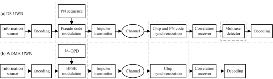
b which represent the final received bits. Fig. 1 compares the frameworks of DS-UWB and WDMA-UWB systems. The dashed boxes indicate the differences between the two systems. At the transmitter, the pseudo code modulation block is omitted owing to the multiple access scheme in WDMA-UWB system. The WDMA-UWB receiver does not employ pseudo-code synchronization and demodulation blocks as well as multiuser detector. The simplified transceiver of WDMA-UWB with lower energy consumption and lower complexity is more suitable for inter-spacecraft communications.
It is obvious that the cross-correlation r k lkl( ) between different users causes MAI. Moreover, rkl is influenced by the orthogonality of pulse waveforms. Therefore, the design of the orthogonal pulse waveforms is the key to MAI suppression for multiuser WDMA-UWB systems.
III. OPTIMIZED ORTHOGONAL PULSE DESIGN
A. General Expression of Combined Waveforms
A large number of methods for UWB pulse design have been developed based on the linear combination of basic pulses, such as Gaussian pulses [22], Hermite polynomial pulses and orthogonal wavelet pulses [15]. The design of pulses can be converted into the optimization of combination coefficients which satisfy the specific objective functions.
In this paper, we use the linear combination of orthogonal
wavelet to design pulses for WDMA-UWB due to the orthogonality and compactly supported character of orthogonal wavelets. The discrete wavelet is usually defined as follows.
/ 2
, ( ) 2 (2 ),
m m
m n t t n
(8)
where m and n are dilation and translation parameters, respectively, and ( )t is the mother wavelet. If the m n, ( )t
constructed by ( )t L R2( ) is a set of orthogonal basis of L R2( ),
the wavelet ( )t is called orthogonal wavelet which has the property of
, ,
(k j( ),t m n( ))t (km j, n), (9)
where k, j, m, n are arbitrary integers. Due to the orthogonality of scaling and translation, the orthogonal wavelets can be applied to the design of orthogonal pulses.
As mentioned above, the pulse for the kth user w tk( ) can be expressed as a linear combination of orthogonal wavelets, Then, the general expression of the combined waveform is given by
1 1, 1 2 2, 2 ,, 1
( ) ( ) ... ( ) = ( ),
k k k k kN kN
ki ki
k k u v k u v kN u v
N
ki u v i
w t t t t
t
(10)where {u vk1,k1,uk2,vk2,...,ukN,vkN} is a set of orthogonal wavelets with
different dilation and translation parameters. { k1, k2,...,kN}
denote the combination coefficients of each wavelets. N is the number of combined wavelet pulses.
B. Coefficients Optimization Based on Interference Alignment According to (10), we derive a new expression of (3) with the general expression of the combined waveforms.
At receiver, the local template signal of the lth user m tl( ) can be expressed as
1 1, 1 2 2, 2 ,, 1
( ) ( ) ... ( ) ( ),
l l l l lN lN
lj lj
l l u v l u v lN u v
N
lj u v j
m t t t t
t
(11)
where { k1, k2,...,kN} denote the combination coefficients
of template signal. In order to derive the new expression of (3) conveniently and calculate the combination coefficients flexibly, we assume that the combination coefficients of local template waveforms are not the same as those of transmitted waveforms. Due to the principle of correlation receiver, the transmitted and local template combined pulses have the reciprocity property. Utilizing the reciprocity property, we can
design the orthogonal combined pulses by using iterative interference alignment algorithm.
Substitute (10) and (11) into (5) and we can get
,
1 1
( ) ( )d
,
s
kl T k k l l
N N
i j ki lj kl
i j
r w t m t t
r
(12)where i j, kl
r is given as ,
, ( ) , ( )d ,
k i ki lj lj
s
i j
kl T u v k u v l
r
t t t (13)where ,i j{1, 2,..., }N , and i j, kl
r represents cross-correlation between the ith combined wavelet of the kth user and the jth combined wavelet of the lth user. Note that if ukiulj or
ki lj
v v and k l , the cross-correlation i j, 0 kl
r , which means the two combined pulse waveforms are completely orthogonal and MAI can be thoroughly suppressed through correlation receivers. However, in the asynchronous system, we cannot ensure k l. The random channel delay leads to imperfect orthogonality of combined waveforms. Thus, the combination coefficients should be optimized to minimize rkl.
Then, the matrix form of rkl can be expressed as
H .
kl l kl k
r R (14)
We define Rkl, l and k as follows , ( i j N N) ,
kl rkl
R (15)
T1 2 ... ,
l l l lN
(16)
T1 2 ... .
k k k kN
(17)
The amplitude parameter Ak in (3) has no effect on the optimization of combination coefficients. For the sake of simplicity, we assume Ak 1. Hence, we can rewrite (3) as
H
1
.
K
l l kl k k l
k
y b n
R (18)Obviously, (18) is similar to the expressions of received signals for the K-user MIMO system based on interference alignment technique [23]. Consequently, IA is an effective technique to suppress interference, which is considered as a
method for designing orthogonal pulses in this paper. More specifically, the matrix k in (18) can be regarded as precoding at transmitters in IA-based MIMO interference network. The correlation matrix Rkl reflects the mutual interference among different users, which is similar to the K-user MIMO interference channel matrix. And the matrix l is used for
interference suppression at receivers. Note that (18) separates
l
and k from rkl in order to conveniently optimize the combination coefficients using interference alignment method. If interference is aligned into the null subspace, the conditions must be satisfied:
H 0, ,
l Rkl k k l
(19)
H
rank(l Rlll) 0. (20)
In this case, MAI is completely suppressed and the desired signals for the lth user can be expressed as
H .
l l ll l l l
y R b n (21)
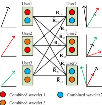
Fig. 2 depicts the interference alignment solution to orthogonal pulse design. We can optimize the combination coefficients using interference alignment to align the interference into the subspace which is orthogonal to the desired signal subspace [24]. A large number of interference-free dimensions contribute to MAI suppression. However, the number of constraint conditions of interference alignment and the computational complexity of (19) increase rapidly as the user number increases. The solution to the interference alignment method is a great challenge in the condition of high user number and imperfect channel estimation.
C. Iterative Interference Alignment Based on Max-SINR As mentioned above, it is difficult to solve the equations of interference alignment directly. An iterative interference alignment algorithm based on network reciprocity was proposed to make the interference alignment achievable [25]. In [19], the proposed iterative interference alignment algorithm optimized the interference suppression matrices to maximize SINR at the receivers, which had significant benefits and was close to the theoretical analysis.
There are several criterions used for the implementation of iterative interference alignment. Minimum interference leakage is one of the iterative criterions [26]. The goal is to minimize the transmitted interference to the non-corresponding receivers. However, the minimum interference leakage criterion makes no attempt to maximize the power of desired signal. In other words, when the transmitted power approaches infinity, the minimum interference leakage algorithm is optimal. Whereas the algorithm is not optimal at low or intermediate signal to noise ratio (SNR). The Max-SINR algorithm is proposed to apply to the application environment at low SNR.
In this paper, we propose IA-OPD by using iterative interference alignment algorithm based on Max-SINR criterion to optimize the combination coefficients l and k.
According to (18), we define the SINR at each receiver. The SINR of the lth receiver can be expressed as
[image:5.595.83.249.85.256.2]11 R 21 R 31 R 12 R 22 R 32 R 13 R 23 R 33 R
H H H
H
SINR = l ll l l ll l .
l
l l l
R R
B
(22)
In (22), the denominator represents the power of noise and interference at the lth receiver, and the numerator represents the power of the desired signal for the lth user. Furthermore, l denotes the covariance matrix of interference and noise, which can be expressed as
H H H H
1
- .
K
l kl k k kl ll l l ll N
k
B R R R R I (23)
Obviously, the matrix l N N
is a symmetric positive definite matrix whose positivity is guaranteed from physical principles. According to the Cholesky Factorization, there exists a unique lower triangular LN N with positive diagonal entries such that
H.
lLL
(24)
Then we define that
H .
l l
α L α (25)
Substituting (24) and (25), we can rewrite (22) as
2 -1
,
SINR = .
,
l ll l
l l l L R
(26)
According to Cauchy–Schwarz inequality, we can get
-1
2
-1 -1
, , , .
l L Rll l l l L Rll l L Rll l
(27)
The SINR of the lth receiver can be rewritten as
2 -1 -1 -1 ,SINR = , .
,
l ll l
l ll l ll l
l l
L R
L R L R
(28)
As a result, the maximum SINR can be obtained as
max -1 -1
SINRl = L Rlll,L Rlll , (29) if and only if l and
-1
ll l
L R are linearly dependent, which can be assumed that
-1
= ,
l kL Rll l
(30)
where k is not zero. In the condition that k is known, the
vector l that maximizes (22) can be designed as
1
1 .
l ll l
l
l ll l
B R
B R
(31)
The reciprocity property of channel is the basic theory of iterative interference alignment algorithm. Note that the combination coefficient vectors l is equivalent to k in the
systems. Hence, we provide a realization of the proposed iterative interference alignment algorithm based on Max-SINR criterion shown in Algorithm 1. The algorithm based on Max-SINR criterion updates the combination coefficient vectors l and k to optimize the objective function in
iterative process and suppress interference step by step at receivers. The iterative process repeats until convergence or the number of iterations reaches the defined limit. As a result, the final coefficient vectors l and k satisfy the optimized criterion which can suppress MAI effectively. In other words, the designed pulses based on optimized coefficients are mutually orthogonal with good cross-correlation characteristic.
Moreover, the correlation matrix Rkl and noise matrix IN
are the useful parameter we need to calculate before initialization. Rkl is available for each user in the condition of accurate estimation of channel delay. And IN depend on the
SNR estimation of WDMA-UWB systems. Consequently, the accurate estimations of channel delay and SNR information are preconditions for the proposed iterative interference alignment algorithm.
Then we analyze the computational complexity of the iterative interference alignment algorithm. The computational complexity mainly depends on matrix operations. The step 3 of the algorithm has the complexity of
O K N
(
2 3)
which mainly depend on the complexity of matrix multiplication and the user number K. Similarly, the step 4 based on matrix inversion and matrix multiplication has the complexity ofO KN
(
3)
. Thus, the overall computational complexity of the algorithm can be expressed asO K N
(
2 3)
. As a matter of fact, N is usually a really small number that has little effect on computational complexity. Hence, the user number K determines the computational complexity of the IA-OPD algorithm.IV. SIMULATIONRESULTSANDANALYSIS
In this section, we evaluate the IA-OPD scheme through numerical simulations. The designed orthogonal pulses are applied to a multiuser WDMA-UWB system for space formation flying to evaluate the cross-correlation, BER performances, user capacity and near-far resistance under the assumption of perfect channel estimation.
A. Simulation Setup
The transmitted bits are modulated to the corresponding orthogonal pulses which are designed by the proposed IA-OPD to achieve WDMA. The repetition period of per pulse Ts is chosen to be 20 ns. The free space channels between spacecraft are considered as the AWGN channels with ideal channel and SNR estimation. The correlation receivers’ local template signals are also designed pulses.
In this paper, we choose the basic orthogonal wavelet pulses based on Meyer wavelet functions for combination. The Meyer wavelet is an orthogonal wavelet proposed by Yves Meyer, which has many advantages for the pulse design, such as compactly supported character in frequency domain, rapid convergence in time domain, symmetry and orthogonality. We
1: Initialization with any unit vectors k, k {1, 2,..., }K 2: Begin iteration
3: Calculate the covariance matrix of interference and noise , {1, 2,..., }
l l K
B for the lth user by using (23)
4: Calculate combination coefficient vector l, l {1,2,..., }K at the lth receiver by using (30)
5: Update the coefficient vector kwhich can be written as
, {1, 2,..., }
k k k K
choose u uk1, k2,...,ukN{0,1,..., }L , where L is the maximum
value of dilation parameter uk. Note that the width of wavelet
pulse influenced by dilation parameter in time domain becomes narrow as uk increases. When uk is very high, the extremely
narrow pulse can result in the expansion of frequency spectrum, the increase in sampling rate and difficult implementation in practice. Hence, the dilation parameter should be kept as small as possible. The translation coefficients do little to help improve the orthogonality of waveforms owing to the channel delay. We do not take the translation coefficients into consideration in this paper. Hence, the Meyer wavelets with different dilation parameters compose a set of basic orthogonal pulses for combination.
Let us consider the allocation principle of Meyer wavelet functions for different users. As mentioned above, we choose the Meyer wavelets according to the dilation parameters. We should ensure that the Meyer wavelets allocated to different users for combination have not exactly the same dilation parameters. When we assume N=2 (the designed pulse is composed of two basic Meyer wavelets), the number of
available combinations of Meyer wavelets is 2 1 L
C . Whereas the number of available combinations is 3
1 L
C when N=3 (the designed pulse is composed of three basic Meyer wavelets). It reveals that the increase of N results in more available combined Meyer wavelets when L is greater than 4.
B. Validity of IA-OPD scheme
Fig. 3 shows the examples of the combined pulse waveforms before and after combination coefficients optimization, and Fig. 4 shows the cross-correlation value between the two combined waveforms. We choose K=2, N=3 and L=3 as an example to intuitively demonstrate the availability of the IA-OPD scheme. It is obvious that the cross-correlation value after the optimization of combination coefficients is much lower than that before optimization. Therefore, the proposed scheme can greatly improve orthogonality of combined pulse waveforms.
[image:7.595.57.271.93.264.2]Fig. 5 shows the convergence of the Max-SINR algorithm. The convergence property influences the availability of iterative algorithm and the number of iterations. In Fig. 5, the curves are all convergent to 0dB as the number of iterations
Fig. 3. Combined pulse waveforms before and after optimization (K=2, N=3,
[image:7.595.315.529.94.270.2]L=3).
Fig. 4. Cross-correlation value between the waveforms before and after
[image:7.595.319.529.307.479.2] [image:7.595.55.268.307.480.2]increase, which indicate that MAI is suppressed gradually in iterative process. We evaluate the convergence of Max-SINR algorithm at different SNR. Obviously, the initializations and rates of convergence for different SNR have distinctive differences. At low SNR, MAI has little effect on the system relative to noise. Hence, the values of SINR are almost equal to those of SNR in the iterative process. Due to the weakened influence of noise, the effect of MAI during initialization increases as SNR increases. At intermediate SNR, the rate of convergence is slower than that of high SNR, which means more iteration number is required to maximize SINR. This is due to the noise in (23) influencing the rate of convergence. In conclusion, the iterative interference alignment algorithm based on Max-SINR criterion can be used for optimization of combination coefficients. In order to achieve good performance and low complexity, we choose 20 iteration number as a compromise.
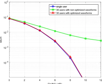
Fig. 6 demonstrates the validity of IA-OPD scheme using optimized pulse waveforms and non-optimized waveforms with K=30, N=3 and L=5. The non-optimized pulse waveforms
are composed by three allocated Meyer wavelets with random combination coefficients, which serve as a contrast to the optimized combined pulses. The curve marked optimized waveforms has a superior BER performance approximating to that of the single user, whereas the BER performance marked non-optimized waveforms is poor due to the imperfect orthogonality of combined pulse waveforms without optimization.
C. BER performance
Fig. 7 shows BER versus SNR with different user number (K=10, 30 and 50) and N=2, L=5. The curve marked 10 users is close to that marked single user. It is obvious in Fig. 7 that the system exhibits gradual performance degradation as the number of user K increase. When the user number is 50, the BER performance is very poor due to the large user number and small values of N and L. As mentioned above, the number of available combinations of basic wavelets is 2
6 15
[image:8.595.61.271.96.270.2]C . When the user number is so large that the available combinations of basic wavelets are not enough to be allocated to different users, the
[image:8.595.318.531.96.271.2]Fig. 7. BER performance for different user number K (N=2, L=5).
Fig. 8. BER performance for different value of N (K=50, L=5).
B
E
[image:8.595.317.531.306.481.2]R
Fig. 9. BER performance for different value of L (K=90, N=3).
[image:8.595.60.271.310.483.2]designed pulses optimized by IA-OPD cannot effectively suppress MAI at transmitters. Hence, the user capacity is limited by N and L.
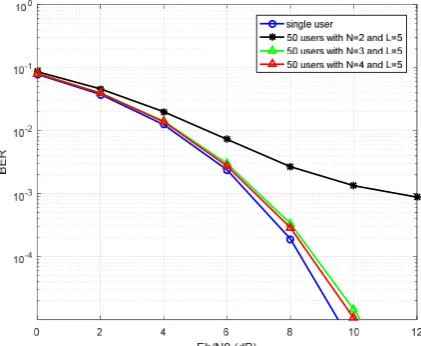
Figs. 8 and 9 depict the BER performances versus the
0 b
E N ratio with different values of N and L, respectively. In Fig. 8, the user number is 50 and we assume L=5, which means the maximum value of dilation parameter we choose is 5. The BER performances are quantified with the number of basic combined wavelets N=2, 3, 4. The curve marked N=2 has the worst BER performance. Obviously, increasing N can give better performance when compared with N=2. Moving from N=2 to N=4, the performance gain around 4dB at the BER of
3
10 . However, the BER performance improve slightly from N=3 to N=4. The results point out that the pulses designed by IA-OPD can effectively suppress MAI when K=50 and L=5. Fig. 9 shows the BER performance when the user number is 90. In the case of large user number, the pulses designed by IA-OPD with N=3 and L=5 cannot provide large user capacity. As expected, the BER performance improves with increasing the maximum value of dilation parameter L, thereby providing more available combinations of basic wavelets. Note that the number of available combinations of basic orthogonal wavelets depends on N and L. The appropriate values of N and L can be chosen by the user number in WDMA-UWB systems. When the active user number is small, we can choose smaller values of N and L for IA-OPD scheme. In this condition, the proposed IA-OPD scheme offers lower computational complexity and easier implementation. When the active user number is large, larger values of N and L are needed for the proposed IA-OPD scheme.
Fig. 10 indicates the BER performances of WDMA-UWB for 30, 50, 90 users with N=3 and L=5. Furthermore, comparisons are made between WDMA-UWB system and DS-UWB system in terms of achievable BER performance and user capacity. The DS-UWB system we simulate uses Kasami codes with a length of 255 to provide MA capacity. At the DS-UWB receivers, multiuser detector based on MMSE
algorithm is used for MAI suppression. Obviously, the BER performance of WDMA-UWB deteriorates slightly as the number of users increases. The performance is still better than that of DS-UWB system with 30 users even if the user number of WDMA-UWB system is 90. The performance of DS-UWB seriously deteriorates in comparison with that of WDMA-UWB for the same user number. When the user number exceeds 50, the DS-UWB communications suffer serious influence due to the strong MAI. Similarly, the traditional MUD algorithms, such as decorrelation (DEC), successive interference cancellation (SIC) and parallel interference cancellation (PIC), achieve the analogical BER performances owing to the simulation results of MMSE multiuser detectors shown in Fig. 10. When the user number is large, the performances of traditional multiuser detectors achieve worse performances than that of WDMA-UWB system without any MUD. Furthermore, it is obvious that WDMA-UWB system has a good BER performance approximating to that of the single-user communication. Hence, MUD algorithms can be omitted at receivers to reduce the complexity and energy consumption. In conclusion, the simulation result demonstrates that the WDMA-UWB system employing IA-OPD scheme can achieve better BER performance and larger user capacity without using any MUD methods at receivers than the traditional DS-UWB system.
D. User capacity
[image:9.595.58.275.93.274.2]In Fig. 11, we evaluate the user capacity of WDMA-UWB system applying orthogonal pulses designed by IA-OPD scheme, for varying N and L. The curve marked N=2 and L=5 is much more sensitive to user number than the other curves. Obviously, the orthogonal pulses with N=2 cannot provide large user capacity. It is worth emphasizing that the performances for N=3 and N=4 deteriorate slightly as the number of users increases. The results point out that the IA-OPD with N=3 and N=4 can both provide large user capacity, which can satisfy the user number of space formation
Fig. 11. BER performance at SNR=6dB for different number of users with
[image:9.595.315.534.95.274.2]capacity is high enough for most practical application scenarios when we assume N=3. Moreover, the performance improves when L increases in the case of N=3. The IA-OPD scheme with larger value of L provides larger user capacity. However, increasing the maximum value of dilation parameter L results in narrower width of basic Meyer wavelet in time domain, which greatly affect the implementation of IA-OPD scheme in practice.
For the WDMA-UWB based space formation flying system, there are dozens of formation spacecraft in general. The values N and L can be chosen by the number of users and the performance requirements of the system. The IA-OPD scheme with large values of N and L can achieve excellent BER performance and user capacity. Conversely, the scheme with small values of N and L offers low complexity and simple implementation in practice at the cost of sacrificing performance and user capacity. Hence, a trade-off between performance and complexity of the system makes the proposed IA-OPD scheme achievable for WDMA-UWB based space formation flying.
E. Near-far resistance
The proposed IA-OPD scheme is applied to the space formation flying system without power control. Due to the constant change of relative positions of spacecraft, the received power from interfering users can be tens of dB larger than the desired signals, which results in a near-far problem. The orthogonal pulses with excellent cross-correlation property for WDMA-UWB system can resist the near-far effect without any power control techniques. Thus, the near-far resistance is a common performance measure for analyzing UWB systems and evaluating the IA-OPD scheme. We consider a 30-user WDMA-UWB system where near-far interference effect is present. Assume that the user 1 is the desired user and user 2-30 are interfering users. The desired user's SNR is fixed on 6dB. The SNR of other users varies from 0dB to 12dB synchronously. Fig. 12 shows the near-far resistance of systems with different values of N and L. It is apparent that the near-far resistance performance of system with N=3 and L=3 is poor due to the small value of L which results in the poor cross-correlation property of designed orthogonal pulses. When the values of N and L are suitable for the number of users (i.e., the curves marked N=2, L=5 and N=3, L=5), the systems are unaffected by the near-far effect. Simulation results demonstrate that the proposed IA-OPD scheme with suitable N and L can design optimized orthogonal pulses whose cross-correlation property counteracts the near-far interference effectively.
V. CONCLUSION
In this paper, an optimized orthogonal pulse design scheme, termed as IA-OPD has been proposed for WDMA-UWB based space formation flying system. We have designed the pulse waveforms employing the combinations of orthogonal wavelet pulses. The combination coefficients were optimized by using
pulses designed by IA-OPD have excellent orthogonal property. The orthogonal pulses used for WDMA-UWB systems can provide large user capacity, good BER and near-far resistance performances without MUD methods. Moreover, the suitable values of N and L make a compromise between performance and complexity of the system. Hence, IA-OPD scheme provides an elegant solution to the problem of pulse design for multiuser WDMA-UWB systems.
REFERENCES
[1] R. Radhakrishnan, W. W. Edmonson, F. Afghah, R. M. Rodriguez-Osorio, F. Pinto, and S. C. Burleigh, “Survey of Inter-Satellite Communication for Small Satellite Systems: Physical Layer to Network Layer View,”
IEEE Commun. Surveys & Tutor., vol. 18, no. 4, pp. 2442-2473, 2016. [2] E. Cianca, T. Rossi, A. Yahalom, Y. Pinhasi, J. Farserotu, and C. Sacchi,
“EHF for Satellite Communications: The New Broadband Frontier,” Proc. IEEE, vol. 99, no. 11, pp. 1858-1881, Nov. 2011.
[3] M. D. Sanctis, E. C., T. Rossi, C. Sacchi, L. Mucchi, and R. Prasad, “Waveform Design Solutions for EHF Broadband Satellite Communications,” IEEE Commun. Mag., vol. 53, no. 3, pp. 18-23, Mar. 2015.
[4] Y. Kim and B. F. Womack, “Performance Evaluation of UWB Systems Exploiting Orthonormal Pulses,” IEEE Trans. Commun., vol. 55, no. 5, pp. 929-935, May 2007.
[5] Y. Nakache and A. F. Molisch, “Spectral Shaping of UWB Signals for Time-Hopping Impulse Radio,” IEEE J. Select. Areas Commun., vol. 24, no. 4, pp. 738-744, Apr. 2006.
[6] Z. Yin, X. Jiang, Z. Yang, N. Zhao, and Y. Chen, “WUB-IP: A High-Precision UWB Positioning Scheme for Indoor Multiuser Applications,” IEEE Syst. J., vol. PP, no. 99, pp. 1-10, 2017.
[7] M. B. Menon, A. Gopakumar, and N. V. Iqbal, “A Hybrid Approach for UWB Pulse Shaping,” in 2ND Int. Conf. Electr. Commun. Syst., Coimbatore, ICECS. India, 2015, pp. 373-377.
[8] X. Luo, L. Yang, and G. Giannakis, “Designing optimal pulse-shapers for ultra-wideband radios,” in Proc. IEEE Conf. Ultra Wideband Syst. Techn., Reston, UWBST. USA., 2003, pp. 349–353.
[9] X. Wu, Z. Tian, T. N. Davidson, and G. B. Giannakis, “Optimal Waveform Design for UWB Radios,” IEEE Trans. Signal Proc., vol. 54, no. 6, pp. 2009-2021, Jun. 2006.
[10] M. Abtahi, J. Magné, M. Mirshafiei, L. A. Rusch, and S. LaRochelle, “Generation of Power-Efficient FCC-Compliant UWB Waveforms Using FBGs: Analysis and Experiment,” J. Lightwave Techn., vol. 26, no. 5, pp. 628-635, Mar. 2008.
[11] A. Milos, G. Molnar, and M. Vucic, “Spectral-Efficient UWB Pulse Shapers Generating Gaussian and Modified Hermitian Monocycles,” in
40th Int. Conv. Inf. Commun. Techn. Electr. Micr., Opatija, MIPRO. Croatia, 2017, pp. 113-118.
[12] G. Molnar, A. Milos and M. Vucic, “Prolate-spheroidal UWB pulse shapers with highly orthogonal impulse responses,” in Proc. 10th Int. Symp. Image & Signal Proc. & Analysis, Ljubljana, ISPA. Slovenia, 2017, pp. 171-176.
[13] S. Kim, Y. Kim, X. Li, and J. Kang, “Orthogonal Pulse Design in Consideration of FCC and IEEE 802.15.4a Constraints,” IEEE Commun. Lett., vol. 17, no. 5, pp. 896-899, May 2013.
[14] I. Dotlic´ and R. Kohno, “Design of the Family of Orthogonal and Spectrally Efficient UWB Waveforms,” IEEE J. Select. Top. Sign. Proc., vol. 1, no. 1, pp. 21-30, Jun. 2007.
[15] X. Wu, X. Sha, C. Li, and N. Zhang, “Orthogonal Wavelet Based Dynamic Pulse Shaping for Cognitive Ultra-Wideband Communications,” in IEEE Global Telecommun. Conf., New Orleans, IEEE GLOBECOM. U.S.A., 2008, pp. 1-5.
[16] V. V. Kumar and V. Ajith, “Wavelet-Based Gaussian Impulse Generation and Optimization for UWB Communication,” in 5th Int. Conf. Adv. Comp. Commun. Inf., Kochi, ICACCI. India, 2015, pp. 214-218.
[18] J. Tang and S. Lambotharan, “Interference Alignment Techniques for MIMO Multi-Cell Interfering Broadcast Channels,” IEEE Trans. Commun., vol. 61, no. 1, pp. 164-175, Jan. 2013.
[19] K. Gomadam, V. R. Cadambe, and S. A. Jafar, “A Distributed Numerical Approach to Interference Alignment and Applications to Wireless Interference Networks,” IEEE Trans Inf. Theory, vol. 57, no. 6, pp. 3309-3322, Jun. 2011.
[20] V. R. Cadambe and S. A. Jafar, “Interference Alignment and Degrees of Freedom of the K-User Interference Channel,” IEEE Trans. Inf. Theory, vol. 54, no. 8, pp. 3425-3441, Aug. 2008.
[21] G. P. Liu and S. Zhang, “A Survey on Formation Control of Small Satellites,” Proc. IEEE, vol. 106, no. 3, pp. 440-457, Mar. 2018. [22] W. Gao, R. Venkatesan, and C. Li, “A Pulse Shape Design for
UltraWideband (UWB) Communications,” in Proc. IEEE Wirel. Commun. & Netw. Conf., Hong Kong, WCNC. China, 2007, pp. 2802-2807.
[23] N. Zhao, F. R. Yu, M. Jin, Q. Yan, and V. C. M. Leung, “Interference Alignment and Its Applications: A Survey, Research Issues, and Challenges,” IEEE Commun. Surveys & Tutor., vol. 18, no. 3, pp. 1779-1803, 2016.
[24] Y. Luo, T. Ratnarajah, J. Xue, and F. A. Khan, “Interference Alignment in Two-Tier Randomly Distributed Heterogeneous Wireless Networks Using Stochastic Geometry Approach,” IEEE Syst. J., vol. PP, no. 99, pp. 1-12, 2017.
[25] K. Gomadam, V. R. Cadambe, and S. A. Jafar, “Approaching the Capacity of Wireless Networks through Distributed Interference Alignment,” in Proc. IEEE Global Commun. Conf., New Orleans, GLOBECOM. USA., 2008, pp. 1-6.